Technical field
The present invention relates to a semiconductor device having a variable resistance element and a method for manufacturing the same.
Background art
In a non-volatile memory field, many studies have been conducted on especially flash memory and also ferroelectric memory (FeRAM), MRAM (Magnetic RAM), OUM (Ovonic Unified Memory), and the like.
In recent years, a Resistance Random Access Memory (ReRAM) different from these non-volatile memories has been proposed. Information can be written into ReRAM by setting a resistance value of a variable resistance layer of a memory cell by applying a voltage pulse and read out information without destruction. With respect to the ReRAM, the cell area is small and a multivalued memory can be realized. Therefore, it is recognized that there is a possibility that the ReRAM will have performance exceeding that of the existing non-volatile memory.
In a status in which it is absolutely necessary to process a great number of information, the ReRAM in which a large volume data can be read and written at low power consumption, high reliability, and high speed is needed. In order to realize this ReRAM, the various technologies are proposed for the variable resistance layer used for the ReRAM (patent document 1 and non-patent document 1).
In patent document 1, a non-volatile element using the variable resistance layer composed of a tantalum oxide layer and a transition metal oxide layer that is formed of a metal different from tantalum is disclosed. In non-patent document 1, the variable resistance element using a tantalum oxide layer having an oxygen concentration gradient across the layer from an interface with one electrode layer to an interface with the other electrode layer as the variable resistance layer is disclosed. Further, it is described that the resistance change described in non-patent document 1 occurs when the oxygen atoms gather at the vicinity of the interface between the electrode layer and the tantalum oxide layer and diffuse by the electric field.
Prior art document
Patent Document
patent document 1: Japanese Patent Application Laid-Open No. 2009-135370
Non-Patent Document
non-patent document 1: IEDM Technical Digest and 2008, page 293
Brief summary of the invention
Problems to be Solved by the Invention
However, the non-volatile element described in patent document 1 has the following problems. The non-volatile element described in patent document 1 has a laminated structure formed of tantalum oxide and titanium oxide and the both transition metal oxide layers have no oxygen concentration gradient.
In a case in which the laminated structure is composed of the transition metal oxide layers, each of which is formed of different metal, as a mechanism of the resistance change, a state in which the oxygen concentration gradient is established in one of the transition metal oxide layers occurs when the voltage is applied. Finally, when the oxygen reaches the other transition metal oxide layer, the resistance change occurs. However, the transition metal oxide layer described in patent document 1 does not have the oxygen concentration gradient. Therefore, a problem in which an excessive voltage is needed until the oxygen reaches the other transition metal oxide layer occurs. Therefore, a problem in which an excessive voltage is required until the oxygen reaches the other transition metal oxide layer and large power is consumed occurs.
On the other hand, in non-patent document 1, the non-volatile element with the oxygen concentration gradient is disclosed. However, the non-volatile element described in non-patent document 1 has the following problems. In the non-volatile element described in non-patent document 1, the oxygen concentration gradient exists from the interface with one electrode layer to the interface with the other electrode layer across the whole element. Therefore, a problem in which oxygen that gathers at the vicinity of the interface between the electrode layer and the tantalum oxide layer diffuses into the electrode layer and whereby, the stable resistance change can not be obtained occurs.
The object of the present invention is to provide a semiconductor device which can solve the above-mentioned problems, can perform a switching operation at low power consumption, and has a stable variable resistance characteristic and a method for manufacturing the same.
Means for Solving the Problems
In order to solve the above-mentioned problem, in a first aspect of the present invention, a semiconductor device in which at least a first electrode, a second electrode, and a layer including a transition metal oxide layer sandwiched between the first electrode and the second electrode are included is provided and wherein the transition metal oxide layer includes a first transition metal oxide layer formed of a first transition metal and a second transition metal oxide layer formed of a second transition metal different from the first transition metal, the first transition metal oxide layer is provided on the first electrode side, the second transition metal oxide layer is provided on the second electrode side, the first transition metal oxide layer and the second transition metal oxide layer are in contact with each other, the first transition metal oxide layer has an oxygen concentration gradient from an interface between the first transition metal oxide layer and the second transition metal oxide layer toward the first electrode side, and the oxygen concentration at the above-mentioned interface is greater than the oxygen concentration on the first electrode side.
Further, in a second aspect of the present invention, a method for manufacturing a semiconductor device which includes at least: (a) a step for forming a first transition metal oxide layer by oxidizing a first transition metal layer provided on a first electrode by plasma oxidation, (b) a step for forming a second transition metal oxide layer formed of a transition metal different from the first transition metal on the first transition metal oxide layer after the above-mentioned step (a), and (c) a step for forming a second electrode on the second transition metal oxide layer after the above-mentioned step (b) is provided.
Advantage of the Invention
By using the present invention, a semiconductor device which can perform a switching operation at low power consumption and has a stable variable resistance characteristic can be realized.
Brief description of the drawings
FIG. 1 is a cross-sectional view showing an example of a semiconductor device according to an exemplary embodiment of the present invention.
FIG. 2 is a cross-sectional view showing an example of a semiconductor device according to an exemplary embodiment of the present invention.
FIG. 3 is a figure showing an example of a composition of an electrode according to an exemplary embodiment of the present invention.
FIG. 4 is a figure showing a composition of a titanium oxide layer according to an example 1 of the present invention.
FIG. 5 is a figure showing an oxygen concentration of a titanium oxide layer according to an example 1 of the present invention.
FIG. 6 is a figure showing a composition of a tantalum oxide layer according to an example 1 of the present invention.
FIG. 7 is a figure showing a crystalline state of a tantalum oxide layer according to an example 1 of the present invention.
FIG. 8 is a figure showing a variable resistance characteristic of an example 1 of the present invention.
FIG. 9A is a figure showing an operation of a variable resistance element according to an example 1 of the present invention. FIG. 9B is a figure showing an operation of a variable resistance element according to an example 1 of the present invention. FIG. 9C is a figure showing an operation of a variable resistance element according to an example 1 of the present invention. FIG. 9D is a figure showing an operation of a variable resistance element according to an example 1 of the present invention.
FIG. 10 is a figure showing a variable resistance characteristic in an example 1 of the present invention.
FIG. 11 is a figure showing a variable resistance characteristic in an example 1 of the present invention.
FIG. 12 is a figure showing a variable resistance characteristic in an example 1 of the present invention.
FIG. 13 is a figure showing a variable resistance characteristic in an example 1 of the present invention.
FIG. 14 is a figure showing a variable resistance characteristic in an example 1 of the present invention.
FIG. 15 is a figure showing a variable resistance characteristic in an example 1 of the present invention.
FIG. 16 is a figure showing an example of a method for manufacturing a semiconductor device according to an example 2 of the present invention.
FIG. 17 is a figure showing an example of a method for manufacturing a semiconductor device according to an example 2 of the present invention.
FIG. 18 is a figure showing an example of a method for manufacturing a semiconductor device according to an example 2 of the present invention.
FIG. 19 is a figure showing an example of a method for manufacturing a semiconductor device according to an example 2 of the present invention.
FIG. 20 is a figure showing an example of a method for manufacturing a semiconductor device according to an example 2 of the present invention.
FIG. 21 is a figure showing an example of a method for manufacturing a semiconductor device according to an example 2 of the present invention.
FIG. 22 is a figure showing an example of a method for manufacturing a semiconductor device according to an example 2 of the present invention.
Description of embodiments
The meaning of the term used in the present invention will be explained before explaining the present invention in detail.
A semiconductor substrate includes a substrate such as a substrate on which a semiconductor device is configured, a single crystal substrate, an SOI (Silicon on Insulator) substrate, a TFT (Thin Film Transistor) substrate, a substrate for liquid crystal production, or the like.
A post-oxidation method is a method in which a metal thin film is formed on a substrate by using a vapor deposition method, a sputtering method, a pulse laser deposition method, or the like and the metal thin film is oxidized by using a thermal oxidation method in an oxygen atmosphere, a plasma oxidation method using an oxygen plasma, or the like to form an oxide film on the substrate.
This exemplary embodiment will be described in detail below with reference to the drawings.
FIG. 1 is a figure schematically showing a structure of a semiconductor device according to this exemplary embodiment.
The semiconductor device shown in FIG. 1 includes at least a first electrode (lower electrode) 101, a second electrode (upper electrode) 102, and a transition metal oxide layer 105 sandwiched between the first electrode 101 and the second electrode 102.
The transition metal oxide layer 105 includes a first transition metal oxide layer 103 formed of the first transition metal and a second transition metal oxide layer 104 formed of a second transition metal different from the first transition metal.
The first transition metal oxide layer 103 is provided on the first electrode 101 side and the second transition metal oxide layer 104 is provided on the second electrode side 102. The first transition metal oxide layer 103 and the second transition metal oxide layer 104 are in contact with each other.
The first transition metal oxide layer 103 has the oxygen concentration gradient from the interface between the first transition metal oxide layer 103 and the second transition metal oxide layer 104 toward the first electrode 101 side. Further, the oxygen concentration at the interface between the first transition metal oxide layer 103 and the second transition metal oxide layer 104 is greater than the oxygen concentration on the first electrode 101 side.
The semiconductor device is configured as mentioned above. Namely, the transition metal oxide layer 105 originally has the oxygen concentration gradient that is essential in a resistance change process. Therefore, a voltage required for switching operation (power consumption) can be reduced. The larger the oxygen concentration gradient is, the more the power consumption can be reduced. The first transition metal oxide layer 103 has the oxygen concentration gradient whose starting point is the interface between the first transition metal oxide layer 103 and the second transition metal oxide layer 104. Therefore, the high speed switching operation can be achieved.
Further, because the transition metal oxide layer 105 has the laminated structure composed of the transition metal oxide layers that are different from each other, the resistance change occurs at the interface between the transition metal oxide layers that are different from each other and it does not occur at the interface between the electrode layer and the transition metal oxide layer. Thus, by setting the interface between the transition metal oxide layers that are different from each other to a place (resistance change place) at which oxygen segregation easily occurs, the oxygen diffusion into the electrode layer can be suppressed and the degradation of the variable resistance characteristic caused by the oxidation of the electrode can be prevented.
In this exemplary embodiment, the transition metal is defined as elements excluding lanthanoid and actinoid among the elements belonging to groups from 3 to 11 of the periodic table of the elements. The transition metal element has a feature in which many electrons that are widely distributed outside the d orbit or the f orbit exist. This behavior means that there are many electrons which can participate in metallic bonding and there are many possible oxidation numbers.
Further, with respect to the oxygen concentration gradient, it is necessary to satisfy a condition in which the oxygen concentration at the interface between the first transition metal oxide layer 103 and the second transition metal oxide layer 104 is greater than the oxygen concentration on the first electrode 101 side. Further, it is further desirable that the oxygen concentration decreases monotonically from the interface between the first transition metal oxide layer 103 and the second transition metal oxide layer 104 to the first electrode 101 side.
It is necessary to satisfy a condition in which the oxygen concentration gradient exists from the interface between the first transition metal oxide layer 103 and the second transition metal oxide layer 104 toward the first electrode 101 side. In other words, the oxygen concentration gradient does not need to exist for the whole from the interface between the first transition metal oxide layer 103 and the second transition metal oxide layer 104 to the interface between the first electrode 101 and the first transition metal oxide layer 103.
Further, another layer other than the laminated structure composed of the first transition metal oxide layer 103 and the second transition metal oxide layer 104 may be interposed between the first electrode 101 and the second electrode 102. For example, a structure in which a layer for controlling a crystal orientation is interposed between the first electrode 101 and the first transition metal oxide layer 103 may be used.
In order to suppress unevenness of the surface of the transition metal oxide layer that is caused by a crystal grain, it is desirable that at least one of the first and second transition metal oxide layers is amorphous. It is further desirable that both the first and second transition metal oxide layers are amorphous. However, if a sufficiently flat surface can be obtained, the transition metal oxide layer may be formed of a polycrystalline material or a microcrystalline material.
At least one of the first transition metal oxide layer 103 and the second transition metal oxide layer 104 is amorphous. Therefore, the surface of the interface between the first transition metal oxide layer 103 and the second transition metal oxide layer 104 is flat. Similarly, because the first transition metal oxide layer 103 is amorphous, when the first transition metal oxide layer 103 and the first electrode 101 are in contact with each other, the surface of the interface between the first transition metal oxide layer 103 and the first electrode 101 is flat. Similarly, because the second transition metal oxide layer 104 is amorphous, when the second transition metal oxide layer 104 and the second electrode 102 are in contact with each other, the surface of the interface between the second transition metal oxide layer 104 and the second electrode 102 is flat. Therefore, variation of the variable resistance path can be reduced among the elements in comparison with a case in which the transition metal oxide layer is formed of a polycrystalline material. This is useful for realizing miniaturization (high integration) of the element.
Further, for example, when the titanium oxide layer is used as the first transition metal oxide layer 103 and the tantalum oxide layer is used as the second transition metal oxide layer 104, it is desirable that titanium oxide in the titanium oxide layer 103 is a stoichiometric composition at the interface with the tantalum oxide layer 104. Furthermore, it is desirable that the oxygen concentration of titanium oxide in the titanium oxide layer 103 is not more than 30% of the stoichiometric composition at the interface with the first electrode 101. By using the above-mentioned structure, an electric current required for the resistance change can be reduced.
It is desirable that the first transition metal oxide layer 103 is formed of any one of titanium oxide, zirconium oxide, and nickel oxide. A film thickness of for example, about 4 nm can be used.
It is desirable that the second transition metal oxide layer 104 is formed of any one of tantalum oxide, zirconium oxide, and silicon tantalum oxide. A film thickness of for example, about 15 nm can be used.
It is desirable that an absolute value of a free energy of oxidation of the second transition metal of which the second transition metal oxide layer 104 is formed is greater than that of the first transition metal of which the first transition metal oxide layer 103 is formed.
The free energy of oxidation can be read as oxygen-transition metal bond strength. Accordingly, it is supposed that the smaller the free energy of oxidation is, the more an oxygen ion or an oxygen defect is diffused. Therefore, by making the absolute value of the free energy of oxidation of the first transition metal small, the oxygen ion or the oxygen defect is largely diffused and whereby, the electric current required for the resistance change can be reduced.
The first electrode 101 has to be electrically-conductive. It may be formed of for example, gold, nickel, cobalt, platinum, ruthenium, iridium, titanium, an alloy of these metals or an oxide or a nitride of these metals, fluoride, carbide, silicide, or the like. A laminated body formed of these materials may be used.
The second electrode 102 has to be electrically-conductive. It may be formed of for example, gold, nickel, cobalt, platinum, ruthenium, iridium, titanium, an alloy of these metals or an oxide or a nitride of these metals, fluoride, carbide, silicide, or the like. Further, a laminated body formed of these materials may be used.
FIG. 2 is a figure schematically showing a step of a method for manufacturing a semiconductor device according to this exemplary embodiment.
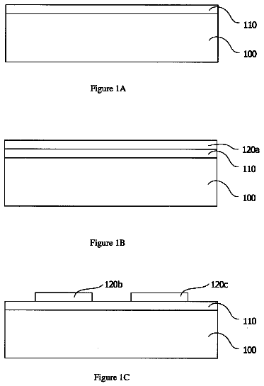
First, in a step (a), the first transition metal layer formed on the first electrode 101 (FIG. 2A) is oxidized by the plasma oxidation to form the first transition metal oxide layer 103 (FIG. 2B). In a step (b) after the step (a), the second transition metal oxide layer 104 that is formed of the transition metal different from the first transition metal is formed on the first transition metal oxide layer 103 (FIG. 2C). In a step (c) after the step (b), the second electrode 102 is formed on the second transition metal oxide layer 104 (FIG. 2D).
In a case in which the first transition metal layer is formed of titanium, amorphous titanium oxide can be obtained by performing the plasma oxidation in the step (a) at a film forming temperature of 250 degrees C. or higher but equal to or lower than 400 degrees C. By forming the amorphous titanium oxide, as described above, the surface of the interface between the first transition metal oxide layer 103 and the second transition metal oxide layer 104 and the surface of the interface between the first transition metal oxide layer 103 and the first electrode 101 become flat. As a result, variation of the variable resistance path can be reduced among the elements in comparison with a case in which the transition metal oxide layer is formed of a polycrystalline material.
Example
In order to explain this exemplary embodiment mentioned above in more detail, an example of this exemplary embodiment will be described in detail below with reference to the drawing.
Example 1
This example 1 will be explained in detail based on the experiment using sample elements 1 to 3.
[Explanation of manufacturing method] A method for manufacturing the sample elements 1 to 3 will be described. A lower electrode having the laminated structure composed of a tantalum nitride layer having a film thickness of 5 nm and a ruthenium layer having a film thickness of 5 nm is formed on a semiconductor (single crystal silicon) substrate. This method is applied to all the sample elements 1 to 3. The lower electrode is formed by continuously forming the film at a temperature of 300 degrees C. by a DC sputtering device.
Next, a titanium layer having a film thickness of 2 nm is formed on the lower electrode. This method is applied to all the sample elements 1 to 3. The titanium layer is formed by depositing a film by the DC sputtering device in which titanium is used as a sputtering target. At this time, argon gas is supplied in a chamber in which the titanium layer is formed at a flow rate of 50 sccm, a film forming temperature is set to 300 degrees C., and a DC power is set to 0.2 kW.
Next, by exposing the titanium layer to the oxygen plasma atmosphere, the titanium layer is oxidized to form the titanium oxide layer. At the time of oxidation, oxygen gas is supplied in the chamber in which the plasma oxidation is performed at the flow rate of 2800 sccm, and exhaust is adjusted so that the pressure is 150 Pa. Further, at the time of oxidation, the film forming temperature is set to 250 degrees C. and an RF power is set to 2.0 kW. When titanium having the film thickness of 2 nm is formed, a plasma oxidation time required to form titanium oxide (TiO2) having a stoichiometric composition is about 300 seconds.
The plasma oxidation times for the sample elements 1, 2 and 3 are set to 60 seconds, 300 seconds, and 600 seconds, respectively. Further, "sccm" is a unit of a flow rate and it means that 1 cm3 of fluid flows in one minute at a temperature of 0 degrees C. and 1 atmospheric pressure.
As a result of the oxidation, in the sample element 1, titanium oxide is formed on the ruthenium layer of which the lower electrode is formed. In the sample elements 2 and 3, titanium oxide is formed on the ruthenium layer of which the lower electrode is formed and the ruthenium oxide layer is formed on the surface of the ruthenium layer.
Next, in the sample elements 1 to 3, the tantalum oxide layer having the film thickness of 15 nm is formed on the titanium oxide layer. The tantalum oxide layer is formed by depositing a film by an RF sputtering device in which tantalum oxide is used as a sputtering target. Oxygen gas and argon gas are supplied in the chamber at the flow rate of 5 sccm and 40 sccm, respectively, the film forming temperature is set to 350 degrees C., and a power is set to 2 kW.
Next, the upper electrode composed of the platinum layer having the film thickness of 40 nm is formed on the tantalum oxide layer. The upper electrode is formed by using an electron beam heating method. At this time, the deposition is performed at a deposition rate of 0.2 nm/sec so as not to give damage to the transition metal oxide layer. This upper electrode is used for all the sample elements 1 to 3.
A layer structure of the sample elements 1 to 3 is shown in table 1.
TABLE-US-00001 TABLE 1 plasma lower Ru Ti film oxidation TaO film upper Pt electrode thickness time thickness electrode sample 5 nm 2 nm 60 sec 15 nm 40 nm element 1 sample 5 nm 2 nm 300 sec 15 nm 40 nm element 2 sample 5 nm 2 nm 600 sec 15 nm 40 nm element 3
[Evaluation of composition] A composition of ruthenium oxide formed in the sample elements 1 to 3 is evaluated by an XPS (X-ray photoelectron spectroscopy). A Al (K.alpha. ray) is used as an X ray source.
An XPS spectrum of an Ru3d (278 to 288 eV) orbit is shown in FIG. 3. As shown in FIG. 3, while Ru4+3d3/2 peak and Ru4+3d5/2 peak that are derived from a metal are observed in an Ru3d region when the plasma oxidation time is 10 seconds, the intensity of Ru4+3d3/2 peak and the intensity of Ru4+3d5/2 peak that are derived from ruthenium oxide are very small.
On the other hand, Ru4+3d3/2 peak and Ru4+3d5/2 peak having strong intensity that are derived from ruthenium oxide are observed in the Ru3d region when the plasma oxidation time is set to a standard condition of 300 seconds or more. However, the intensity of Ru4+3d3/2 peak and the intensity of Ru4+3d5/2 peak that are derived from metallic ruthenium are extremely small.
As described above, it is understood that because the absolute value of the free energy of oxidation of ruthenium is sufficiently small in comparison with the absolute value of the free energy of oxidation of titanium, the oxidation of ruthenium does not occur until the titanium layer is completely oxidized.
From this result, it is understood that the titanium oxide layer having a large oxygen concentration gradient is formed on the ruthenium lower electrode in the sample element 1 to which a short plasma oxidation time is applied. On the other hand, it is understood that the ruthenium oxide layer and the titanium oxide layer having a small oxygen concentration gradient are sequentially formed on the ruthenium lower electrode in the sample elements 2 and 3 to which a long plasma oxidation time is applied.
Next, the composition of the titanium oxide layer formed in the sample elements 1 to 3 is evaluated by the XPS. The Al (K.alpha. ray) is used as the X ray source.
FIG. 4 shows the XPS spectrum of a Ti2p (455 to 470 eV) orbit and an Ols (525 to 540 eV) orbit.
FIG. 4(a) shows the spectrum of the Ti2p orbit of the sample elements 1 to 3. FIG. 4(b) shows the spectrum of the Ols orbit of the sample elements 1 to 3.
It is understood that a composition ratio (O/Ti) of titanium oxide that is obtained from an area of the spectrum of the Ti2p orbit and an area of the spectrum of the Ols orbit shown in FIG. 4 is almost 2 and titanium oxide (TiO2) having a stoichiometric composition is formed on the surface of the titanium oxide layer.
On the other hand, in the sample elements 1 to 3, because the plasma oxidation method of titanium is used to form the titanium oxide layer, the oxygen concentration gradient is formed at the inside of the titanium oxide layer.
FIG. 5 shows a result of a comparison of the oxygen concentration expected from a ratio of the areas of the XPS spectrums of the Ti2p orbit and the Ols orbit.
In FIG. 5, the horizontal axis is a milling time and it corresponds to a depth from the surface of the titanium oxide layer.
FIG. 5 shows measurement results for two sample elements that are oxidized by the plasma oxidation for 10 seconds and 1200 seconds, respectively.
From FIG. 5, it is understood that the oxygen concentration is a stoichiometric composition at the surface of the titanium oxide layer and decreases in a direction toward the ruthenium lower electrode. Further, it is understood that the shorter the oxidation time is, the more the oxygen concentration of the sample element decreases from the stoichiometric composition.
Further, it is shown in non-patent document 2 that when the plasma oxidation of titanium is performed at 400 degrees C., the amorphous titanium oxide is obtained. It is recognized that the amorphous titanium oxide is crystallized by an annealing process at 600 degrees C. or more. The annealing process at 600 degrees C. or more is not performed for the sample elements 1 to 3. Accordingly, we can say that the titanium oxide layer is amorphous in the sample elements 1 to 3. Even when the variable resistance element of this example is mounted on a wiring layer of an integrated circuit, a process for manufacturing the wiring layer is performed at a temperature of 600 degrees C. or less. The inventors of the present invention confirmed that the state of the titanium oxide layer is kept amorphous from a diffraction image by a cross-sectional TEM analysis. [non-patent document 2] G. He et al., Chemical PhysicsLetters, Vol. 395, pp. 259, 2004
Next, a result of an evaluation in which the composition of tantalum oxide formed in the sample elements 1 to 3 is evaluated by the XPS will be described. The Al (K.alpha. ray) is used as the X ray source.
FIG. 6(a) shows the XPS spectrum of a Ta4f (25 to 35 eV) orbit and FIG. 6(b) shows the XPS spectrum of an Ols (525 to 545 eV) orbit. As shown in FIG. 6, a Ta5+4f5/2 peak and a Ta5+4f7/2 peak that are derived from tantalum oxide and a Ta04f5/2 peak and a Ta04f7/2 peak having a weak intensity that are derived from metallic tantalum are observed in a Ta4f region. Further, the peak derived from the Ta--O bond is observed in an Ols region. The composition ratio of tantalum oxide (O/Ta) that is obtained from the spectrum areas of these is approximately 2.5. Accordingly, it is understood that tantalum oxide (Ta2O5) having the stoichiometric composition is formed.
Next, the crystallinity and the crystallization temperature of the tantalum oxide layer are examined by the XRD (X-ray diffraction). The tantalum oxide layer is formed on a silicon by the above-mentioned sputtering method and after that, the samples are produced by performing the high temperature annealing process at 500, 600, 700, and 800 degrees C. in the oxygen atmosphere.
FIG. 7 shows the XRD spectrum of each sample. From FIG. 7, it can be confirmed that tantalum oxide is crystallized at 700 degrees C. or more and a
surface, a
surface, and a
surface are formed. Further, the peak observed at a temperature lower than 700 degrees C. is derived from silicon of the substrate. Here, the annealing process is not performed at 700 degrees C. or more for the above-mentioned sample elements 1 to 3. Accordingly, we can say that the tantalum oxide layer is amorphous. Even when the variable resistance element of this example is mounted on a wiring layer of an integrated circuit, a temperature of the process for manufacturing the wiring layer is 600 degrees C. or less. Therefore, the state of the titanium oxide layer is kept amorphous.
[Variable resistance characteristic] Next, the variable resistance characteristic of the sample element 2 will be described. In the sample element 2, the variable resistance layer has the laminated structure composed of an amorphous titanium oxide layer and an amorphous tantalum oxide layer. In the sample element 2, the oxygen concentration in the amorphous titanium oxide layer decreases in a direction toward the lower electrode side from the interface between the amorphous titanium oxide layer and the amorphous tantalum oxide layer. The upper electrode has a planar shape whose size is 50 nm square.
Because the sample element 2 in an initial state in which the film has just been formed is an insulating body, a Forming operation is performed to form a current path in the oxide film by applying a pulse voltage. After that, by applying a voltage to the sample element 2, data writing of a high resistance state (reset state) `0` and a low resistance state (set state) `1` is performed.
In this case, the writing of 0.fwdarw.1 is called a set operation and the writing of 1.fwdarw.0 is called a reset operation. A voltage in the set operation is called a set voltage and a resistance in the set state is called a set resistance. Similarly, a voltage in the reset operation is called a reset voltage and a resistance in the reset state is called a reset resistance.
FIG. 8(a) shows a state of the resistance change (formation of the variable resistance path) by the Forming The electric current sharply increases when the applied voltage is around 8 V and at this time the variable resistance path is formed. FIG. 8(b) shows a state of the resistance change when a positive bias is applied to the upper electrode after the Forming is performed. FIG. 8(c) shows a state of the resistance change when the positive bias is applied to the upper electrode after the resistance has been changed to the high resistance. The number shown in the figure indicates the order of the voltage sweep.
Further, a variable resistance mechanism of a lamination type variable resistance element represented by the sample element 2 will be described. A state before the variable resistance path is formed (in a range between 0 to 2 volts) shown in FIG. 8(a) indicates an initial leak current characteristic of the variable resistance layer. From the analysis of the current-voltage characteristic, it is known that the rate of the initial leak current is controlled in the tantalum oxide layer and a conduction mechanism of it is of a Poole-Frenkel type (PF type) (non-patent document 3).
On the other hand, after the Forming is performed, a path having a different conduction mechanism is generated in parallel. The resistance of this path is very small compared to the resistance of the path having the PF type conduction mechanism. Accordingly, most of the electric current that flows between the electrodes flows through this path.
Here, it is usually understood that the variable resistance path formed by the Forming is equivalent to a breakdown path formed when a breakdown voltage is applied to an insulating body. The breakdown path is investigated in detail by using silicon oxide used for the gate insulating film or the like. In a study using silicon oxide, it is known that the oxygen defect is formed in the path and the leak current path is generated by this (non-patent document 4).
Based on the estimation from this, it is estimated that the variable resistance path of the tantalum oxide layer formed after the Forming is performed is Ta2O5-X in which oxygen is removed from tantalum oxide (Ta2O5) having the stoichiometric composition. [non-patent document 3] E. Atanassova, et al., Microelectronics Reliability, Vol. 42, pp. 157, 2002 [non-patent document 4] X. Li et al., APL, Vol. 93, pp. 072903, 2008
As shown in FIG. 8(b), the state of the sample element 2 to which the Forming has been performed is changed from a low resistance state to a high resistance state by applying the positive bias to the upper electrode. The high resistance state occurs with good reproducibility when the applied voltage is around 2 volts and the low resistance state is stable when the applied voltage is in a range between 0 volt and about 2 volts.
Further, as shown in FIG. 8(c), the state of the sample element 2 in the high resistance state is changed from the high resistance state to the low resistance state by applying the positive bias to the upper electrode. The low resistance state occurs with good reproducibility when the applied voltage is around 4 volts and the high resistance state is stable when the applied voltage is in a range between 0 volt and about 4 volts.
It is understood that the resistance change to the high resistance state or the low resistance state is caused by movement of an oxygen ion (O--) in the variable resistance path. Namely, in the sample elements 1 to 3, it is understood that the resistance change is caused by the change in the oxygen ion density at the interface between the titanium oxide layer and the tantalum oxide layer or a tantalum oxide region adjacent to the titanium oxide layer.
A mechanism of the resistance change caused by the movement of the oxygen ion will be described in detail by using the sample element 2 as an example with reference to an energy band diagram (band diagram).
FIG. 9A schematically shows a structure and a band diagram of the sample element 2 before the Forming is performed. In a band diagram 905 a band diagram 906, a vertical axis is energy E and a horizontal axis is along a film thickness direction (Z) and a direction (X) perpendicular to the direction. The band diagram 905 and the band diagram 906 correspond to a region shown by the broken line indicated in FIG. 9A. An electron can not exist in an energy region filled with gray in the diagram and the region is called an energy gap. In the band diagram 905, a symbol EC represents a lowermost end of a conduction band, a symbol EV represents an uppermost end of the valence band, and a symbol EF represents Fermi Energy Level of the electrode.
A second layer 904 shown in FIG. 9A is formed of amorphous tantalum oxide having the stoichiometric composition and includes the oxygen defect. Although the energy gap of Ta2O5 is about 4.5 eV and an insulating body, it is understood that the defect level caused by the oxygen defect exists in the energy gap. The PF type electron conduction occurs via this defect level.
A first layer 903 shown in FIG. 9A is formed of amorphous titanium oxide and it is understood from a result of the XPS that titanium oxide on the tantalum oxide layer side has the stoichiometric composition. As described above, the percentage of oxygen continuously decreases in a direction toward a first electrode 901.
FIG. 9B schematically shows a structure and a band diagram of the sample element 2 after the Forming has been performed. In the band diagram 905 and the band diagram 906, the vertical axis is energy E and the horizontal axis is along a film thickness direction (Z) and a direction (X) perpendicular to the direction. The band diagram 905 and the band diagram 906 correspond to a region shown by the broken line indicated in FIG. 9B.
As described above, it is understood that the breakdown path caused by the oxygen defect is formed in the variable resistance layer after the Forming has been performed. A state in which the breakdown path is formed is indicated by circles. It is understood that when many oxygen defects occur, an energy band structure of tantalum oxide largely changes from the band structure of tantalum oxide (Ta2O5) having the stoichiometric composition. Therefore, usually, the energy gap becomes small. As a result, the resistance value of this breakdown path decreases. Therefore, the resistance value of the variable resistance layer largely decreases. This corresponds to the low resistance state of the variable resistance element of this example.
FIG. 9C schematically shows a structure and a band diagram of the sample element 2 in the high resistance state. In the band diagram 905 and the band diagram 906, the vertical axis is energy E and the horizontal axis is along a film thickness direction (Z) and a direction (X) perpendicular to the direction. The band diagram 905 and the band diagram 906 correspond to a region shown by the broken line indicated in FIG. 9C.
As described above, it is understood that the high resistance state occurs by the segregation of the oxygen ion at the interface between the titanium oxide layer and the tantalum oxide layer or in the tantalum oxide region adjacent to the titanium oxide layer. As a result, the large energy gap occurs in a band of the interface and this is a mechanism by which the high resistance state occurs.
The description continues in the full USPTO document.
 Lapsed, fee not paid8 drawings