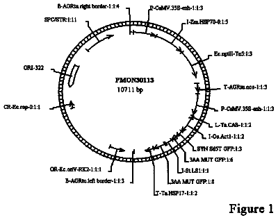
 Lapsed, fee not paid3 drawings
Biotech & Lab · US 8,759,609 B2
Methods for corn transformation
The present invention relates to a novel transformation system for generating transformed corn plants.
US 8,764,272 B2 · Assignee: W. R. Grace & Co., -Conn. · Inventors: Hazrati; Kati et al.
Sheet 1 of 9 from the published document. All sheets in the USPTO PDF
The invention provides `thixotropy` monitoring, by measuring the reversible, time-dependent reduction in viscosity occurring when concrete is subjected to mixing, and employs a mixing drum and conventional slump monitoring equipment as used on ready-mix trucks. In one embodiment, the drum is rotated until concrete is completely mixed; the speed is altered, such as by increasing it to a predetermined level; and the energy required to rotate the drum (ER) is monitored; the maximum (ER-MAX) and minimum (ER-MIN) values are recorded in computer memory; and these values are compared to pre-determined (target) values. Rheology factors (including viscosity, yield stress, and/or thixotropy) can be adjusted accordingly by adding liquid component(s) into the mix. This method, suitable for delivery of highly fluid concrete speed such as SCC, can involve transit and placement rheology targets during monitoring.
The monitoring and control of concrete "slump" in ready-mix delivery trucks has been described in a number of published patent documents, which are summarized below and incorporated herein by reference. In U.S. Pat. No. 4,008,093, Kitsuda et al. disclosed that the slump property of a concrete mix could be controlled by measuring electrical energy required for rotating the mixing drum and allowing the truck operator to adjust slump by adding water to maintain it within a certain slump range, thereby making longer transportation of concrete by truck mixer possible. In U.S. Pat. No. 5,713,663, Zandberg disclosed that concrete slump could be controlled by monitoring torque on the hydraulic drive of the truck mixing drum and automatically adding a liquid component to adjust the concrete mix to a desired slump, as detected by a minimum torque loading on the mixing drum. In U.S. Pat. No. 6,484,
8 of 9 drawing sheets so far from the published document, cropped to the drawing. Every sheet is in the USPTO PDF.
What the patent claimed, word for word. All of it is now free to use.
The present invention relates to manufacturing of concrete, and more particularly to a method for monitoring and control of thixotropy of concrete in a mixing drum.
The monitoring and control of concrete "slump" in ready-mix delivery trucks has been described in a number of published patent documents, which are summarized below and incorporated herein by reference.
In U.S. Pat. No. 4,008,093, Kitsuda et al. disclosed that the slump property of a concrete mix could be controlled by measuring electrical energy required for rotating the mixing drum and allowing the truck operator to adjust slump by adding water to maintain it within a certain slump range, thereby making longer transportation of concrete by truck mixer possible.
In U.S. Pat. No. 5,713,663, Zandberg disclosed that concrete slump could be controlled by monitoring torque on the hydraulic drive of the truck mixing drum and automatically adding a liquid component to adjust the concrete mix to a desired slump, as detected by a minimum torque loading on the mixing drum.
In U.S. Pat. No. 6,484,079, Buckelew et al. disclosed that the slump control of Zandberg et al. could be remotely monitored. The status of the delivery truck could be reported and tracked using wireless transmission and global positioning units.
In application Ser. No. 09/845,660 (Publication No. US2002/0015354A1), Buckelew disclosed that continuous monitoring of slump, using GPS positioning systems, could help to detect whether the truck operator or construction foreman added water to make the concrete easier to spread (paragraphs 0005-0006). This unauthorized addition of water could work detriment to the concrete mix by decreasing compressive strength. Thus, Buckelew taught that slump be monitored numerous times during delivery, and the slump data downloaded by wireless transfer at the installation site.
In U.S. application Ser. No. 10/599,130 (Publication No. 2007/01856A1), Cooley et al. disclosed a system for calculating and reporting slump in a truck drum that had a hydraulic sensor coupled to the hydraulic drive and a rotational speed sensor connected to the drum. Both sensors were connected to a wireless communication system. This permitted modifications to be made to the truck operation during the delivery service.
The monitoring of concrete slump involves calibrating the values obtained from the hydraulic or electrical sensor on a mixing truck and correlating these with slump values obtained using a standard slump cone test. In a standard slump cone test, a 12-inch truncated cone containing fresh concrete is removed to permit the concrete to drop, and the vertical height drop of the concrete is measured (ASTM C143-05).
The present inventors believe that the slump of a concrete mix does not provide an accurate indication of its segregation resistance. This resistance to segregation refers to the ability of the concrete mix to cohere with uniform consistency such that separation of component solids is avoided. Concrete is a suspension made from mixing water, cement, and aggregate (e.g., sand, crushed gravel). The denser material (usually aggregate) tends to sink downwards when mixing stops. The turn-screw effect of the blades or paddles mounted inside the rotating drum of the truck can exacerbate segregation by pushing the aggregate in one direction along the axis of drum rotation.
Segregation can lead to diminishment of the concrete mix "pumpability" (i.e., ability to be conveyed through a conduit) as well as of its "finishability" (i.e., ability to provide smooth but dense outer surface). On the other hand, it is important to control cohesiveness so that it does not become excessive to the point of hindering ease of pumping or finishability.
In U.S. Pat. No. 6,227,039, Te'eni stated that "different concrete mixes can exhibit equal workabilities (slump) when measured by different techniques and yet can possess totally different rheological properties relating to their suitability for commonly required applications," such as pumping (col. 2, II. 14-20). He disclosed a shearing sensor unit having vibrating and shear-inducing devices and sensors for measuring stress and acceleration (FIG. 1; col. 6-7). A piston pushed the shear box downwards, forcing the concrete sideways out of open ends of a U-shaped shear box, where multiple sensors monitored the resistance to movement of the piston rod (col. 7, I. 59--col. 8, I. 9). The shear box could be mounted within the truck drum to transmit data wirelessly to a mixing plant so that a rheological profile could be generated based on workability, stress state sensitivity, stress distribution, shear rate sensitivity, vibration decay, vibratability, pumpability, and deformability (col. 8, II. 59--col. 9, II. 39).
However, mounting the U-shaped box shear-sensing device of Te'eni within the mixing drum of a concrete delivery truck would appear problematic. The truck operator would need to ensure that the shear box was submerged under the concrete mix, rather than located upside down within the drum above the concrete mix, so that the sensors could operate properly. The truck operator might be required to shut down the engine to ensure that its vibration would not interfere with the operation of the vibration sensors on the shear box. Moreover, during transit, the shear box would likely be crushed by the tremendous weight of the aggregate, leading to repair problems. Having a shear box protruding within the mixing drum could also interfere with operation of the mixing paddles on the concrete mix.
Thus, an objective of the present invention is to monitor and to control the rheology of the concrete mix during transit from the ready-mix plant (or dispatch center) to the site of placement (or pouring), using the truck's mixing drum as a rheometer and monitoring equipment that is presently available in the concrete industry, without having to mount U-boxes or other pneumatic or vibratory devices within the drum.
Another objective of the present invention is to minimize the number of rheology factors that require assessment and to avoid having to analyze certain factors, such as vibration decay or vibratability, altogether.
A further objective of the present invention is to provide a method for controlling the rheology of highly flowable concretes, such as Self Consolidating Concrete ("SCC"). SCC is concrete that is able to flow and to consolidate under its own mass without vibration. SCC is highly filled, with typically about 70% aggregate by volume, as well as highly fluid. Due to this high degree of fluidity (characterized as "slump flow"), the horizontal flow (spread) rather than the vertical drop of the concrete placed in a slump cone is measured (ASTM C 1611-05). SCC typically exhibits 18-32 inch slump flow when measured by this slump cone method.
The prior art for estimating slump in a concrete mixer does not provide for estimation or monitoring of slump flow. Moreover, the use of the afore-mentioned slump cone method for measuring slump flow is not believed by the present inventors to provide an accurate means for assessing SCC or other highly fluid concrete mixes.
Hence, a novel method for monitoring and control of rheology of concrete mixes in a concrete delivery mixing truck is needed.
In surmounting the disadvantages of the prior art, the present invention provides a novel method for monitoring and control of thixotropy in concrete mixing drums, including those installed on delivery mix trucks, thus allowing monitoring and control of thixotropy while in transit from plant to placement. The method can be used with conventional slump monitoring equipment on such delivery trucks, and is preferably used to supplement conventional slump monitoring.
The novel method of the present invention builds inventively upon the approach of Amziane, Ferraris and Koehler in "Measurement of Workability of Fresh Concrete Using a Mixing Truck," Journal of Research of the National Institute of Standards and Technology (Vol. 110, No. 1, January-February 2005, pages 55-66), which is incorporated herein by reference. Amziane et al. taught that yield stress and plastic viscosity were important for studying flow behavior; and furthermore that the power (required to rotate the drum) and shear rate (rotation speed) could be plotted on a graph, so that slope of the resulting curve indicated plastic viscosity, while the intercept of the curve at zero shear rate indicated the yield stress.
The present invention employs conventional slump monitoring systems to monitor a rheology factor known as "thixotropy." While "yield stress" refers to the amount of mixing force required for initiating flow and "plastic viscosity" refers to the resistance to flow once yield stress is exceeded, the term "thixotropy" refers to the reversible, time-dependent reduction in viscosity that occurs when the concrete is subjected to shear forces (e.g., mixing). When concrete is at rest, a thixotropic internal structure is formed by internal bonding of the hydrating cement and other forces. The result is a high static yield stress reflected by the amount of energy required to start mixing the material. Mixing forces work to disrupt the thixotropic structure, lowering the resistance to flow, but the thixotropic internal structure returns when shearing (mixing) forces diminish.
An exemplary method of the present invention for monitoring thixotropy of a concrete mix comprises: (A) rotating a concrete mix, or the components of a concrete mix, in a concrete mixing drum at a first mixing speed (S.sub.1) to mix completely the concrete mix components or otherwise to maintain the concrete mix in a completely mixed state; and (B) measuring the thixotropy of the concrete mix by monitoring the reversible, time dependent change in viscosity occurring after rotational speed of the concrete mix in the mixing drum is altered by changing to another speed (S.sub.2) that is different from S.sub.1 (e.g., preferably S.sub.2 is greater than S.sub.1).
An example of the method of the invention involves measuring energy after speed increase. This exemplary method comprises, after step A, increasing the speed of the mixing drum to a faster constant mixing speed S.sub.2 such that S.sub.2 is at least one half revolution per minute faster than S.sub.1; monitoring the energy required to rotate the mixing drum (E.sub.R) at constant speed S.sub.2 until after E.sub.R levels off over time; storing in computer (accessible) memory a first value corresponding to the maximum energy required to rotate the mixing drum (E.sub.R-MAX) after increasing the mixing speed from S.sub.1 to S.sub.2 and also storing in computer memory a second value corresponding to the average energy required to rotate the mixing drum during a predetermined time period wherein the energy required to rotate continuously the mixing drum at constant speed S.sub.2 begins to level off to a minimum level (E.sub.R-MIN) after dropping from E.sub.R-MAX; comparing said E.sub.R-MAX and E.sub.R-MIN values to at least one set of predetermined target values stored in computer memory; and adjusting yield stress, plastic viscosity, or thixotropy of said concrete mix contained in said rotating mixing drum using a liquid component.
One can therefore measure the overall decrease in energy required to rotate the mixing drum after increasing drum speed. (The inventors refer to this as the "torque fade" variation of the method of the invention). Accordingly, one can derive a value by taking the difference between (or the ratio of) E.sub.R-MAX and E.sub.R-MIN and by comparing this value to predetermined (target) rheology value ranges stored in computer memory (e.g., ranges based on differences between, or ratios of, predetermined E.sub.R-MAX and E.sub.R-MIN values).
Another preferred example involves measuring energy required to rotate the mixing drum in each of the periods after increasing and after decreasing drum speed. The inventors call this the "trapezoid" variation, because plotting the resultant E.sub.R values against speed on a graph produces a trapezoid shape. This variation of the method comprises, after step A, rotating the mixing drum at a higher speed (than mixing speed S.sub.1 in step A), or more preferably at constant speeds that are increased in step-wise fashion, for specified time periods. The energy needed for rotating the concrete mix (E.sub.R) at each speed interval is determined. These E.sub.R values are stored in computer memory. (If depicted on a two-dimensional graph, these E.sub.R values would illustrate a first stress curve in terms of E.sub.R vs. speed). The concrete mix is rotated at the same higher speed and E.sub.R is again calculated for the specified time period, but only once E.sub.R has leveled off. Again, this leveling-off illustrates an aspect of the thixotropy of the concrete mix. In other words, mixing causes a breakdown of the three-dimensional structure formed due to thixotropy, which results in lower resistance flow for a given shear rate (mixing speed). When a constant, minimum resistance to flow is achieved for a given mixing speed, the thixotropic built-up structure is disrupted. Upon a reduction in shear rate (mixing speed), the thixotropy built-up structure is restored. This procedure (wherein E.sub.R is again calculated for the specified time period but only once E.sub.R has leveled off) is repeated at a different speed (this time at preferably a lower speed rather than at higher speed) so that a second set of E.sub.R values can be determined and stored in computer memory (and more preferably a succession of progressively lower speeds is used and measured at such lower speeds for the specified time). (If depicted on a two-dimensional graph, this second set of E.sub.R values would illustrate a second stress curve in terms of E.sub.R vs. speed). A thixotropy value (corresponding to trapezoid area between stress curves when plotted on a graph) is compared to predetermined (target) ranges stored in computer-accessible memory.
Thus, another exemplary method of the invention for monitoring concrete rheology comprises: rotating a concrete mix, or the components of a concrete mix, in a concrete mixing drum at a first mixing speed (S.sub.1) to mix completely the concrete mix components or otherwise to maintain the concrete mix in a completely mixed state; rotating said concrete mix at a first constant drum speed (S.sub.1) and at least one higher speed (S.sub.2) for specified time periods to determine the energy needed for rotating the concrete mix (E.sub.R) at each speed; storing said determined first energy value (E.sub.R1) and second energy (E.sub.R2) values in computer memory; rotating said concrete mix at S.sub.2 to determine a third energy value (E.sub.R3) for a specified time period, but determining the third energy value (E.sub.R3) only after E.sub.R has leveled off (thereby indicating the thixotropy of the concrete mix), and storing E.sub.R3 in computer memory; rotating said concrete mix at a speed (S.sub.3) different from (and this time preferably lower than) S.sub.2 to determine a fourth energy value (E.sub.R4) for a specified time period, but determining a fourth energy value (E.sub.R4) only after E.sub.R has leveled off (thereby indicating that the concrete mix has reached a minimum resistance to flow for the given mixing speed), and storing E.sub.R4 in computer memory; comparing relative rheology values (in terms of at least two values selected from yield stress, plastic viscosity, and thixotropy) based on said determined E.sub.R1, E.sub.R2, E.sub.R3, and E.sub.R4 values with predetermined values (in terms of at least two values selected from yield stress, plastic viscosity, and thixotropy) stored in computer memory; and adjusting rheology of said concrete mix using a liquid component.
The methods of the present invention are suitable for controlling concrete rheology on delivery vehicles (e.g., trucks) having a mixing drum and automated slump monitoring and liquid dispensing equipment. Thixotropy as well as slump and other rheology values can be adjusted automatically and kept with predetermined (target) ranges. The invention is suitable for highly fluid concrete such as self-consolidating concrete (SCC). Ideally, SCC should possess a low yield stress so that it flows and consolidates under its own mass; but its static yield stress, when mixing forces diminish, should allow it to resist segregation and partially to support its own weight, reducing lateral forces transmitted to formwork (mold). At placement, it is desirable for SCC to have a slump flow of 18-32 inches; but during transit, this high fluidity could give rise to splashing on bumpy or elevated roads, causing material loss (through mixing drum opening) and lack of accuracy in slump monitoring.
It is therefore useful to lower slump during transport to between 0-11 inches (cone test) and to employ the thixotropy monitoring method of the present invention. At some point during delivery, the decision is made to increase slump and to monitor thixotropy to confirm that it meets a "placement profile" (e.g., for SCC). Exemplary methods thus comprise converting the mode of the truck monitoring system from a predetermined (target) transit rheology to a placement rheology. The point of conversion can be determined by considering temperature (ambient and concrete), humidity, concrete mixture proportions, time to discharge, time required for converting from transit to placement rheology, nature of the terrain (e.g., whether smooth, bumpy, elevated), and other inputs (e.g., estimated time of arrival using GPS).
For SCC applications in particular, it is desirable to ensure that the rheology factors (yield stress, plastic viscosity, and thixotropy) are monitored, because avoiding segregation during transit is important for avoiding segregation when SCC is placed (discharged) into the formwork.
Further advantages and features of the invention may be described hereinafter.
Further advantages and features of the present invention may be more readily comprehended when the following detailed description of preferred embodiments is taken in conjunction with the appended drawings wherein
FIG. 1 is a composite graphical illustration
FIG. 2 is a graphical illustration of an aspect of an exemplary method of the invention wherein the rotational speed of a mixing drum containing a fresh concrete mix is increased by increments over periods of time;
FIG. 3A is a graphical illustration of an exemplary method of the invention wherein the energy required to rotate the mixing drum containing a fresh concrete mix is continuously measured at a first constant rotation speed (S.sub.1) for a continuous period of time;
FIG. 3B is a graphical illustration of the exemplary method of FIG. 2A wherein the rotational speed of the mixing drum is increased to a higher constant rotational speed (S2), and the energy required to rotate the mixing drum containing the fresh concrete mix is measured for a second continuous period of time (as designated at E.sub.R2), and then the thixotropic built-up structure of the mix is destroyed, as indicated by a leveling off of energy (E.sub.R3) which is calculated over a subsequent continuous time period;
FIG. 3C is a graphical illustration of the exemplary method of FIG. 2B wherein the rotational speed (S.sub.3) is decreased (from level S.sub.2 to S.sub.1) and the energy required to rotate the mixing drum (E.sub.R) is monitored until it begins to level off over time (again indicating the mix has reached a minimum resistance to flow for the given mixing speed) and then measured (E.sub.R4) over another continuous period of time; and
FIG. 4 is a graphical illustration of the exemplary method of FIGS. 2A-2C wherein the energy values E.sub.R1, E.sub.R2, E.sub.R3, and E.sub.R4 for rotating the mixing containing the concrete mix are plotted against drum rotation speed (shear rate), thereby revealing a trapezoid whose area provides an indication of the thixotropy characteristic of the concrete mix;
FIG. 5 is a graph representing an optimal range of rheological parameters, wherein correct rheology at placement (designated at C and D within a "workability box" surrounding C and D) can be provided by using the method of the present invention wherein additives are dosed at the proper amount and at the proper times, whereas improper rheology at placement (designated at A and B) can obtained with no additive (e.g., A) or with additive (e.g., B) if the improper amounts and/or times are used;
FIGS. 6-7 are graphs illustrating multiple predictions of rheology over time based on the use of different additives at different times;
FIG. 8 is a flow chart showing an exemplary system for monitoring and controlling concrete rheology in a concrete delivery in which the method of the invention can be implemented;
FIG. 9 is a flow chart illustrating a typical concrete mix management and optimization system in which an exemplary method of the invention for monitoring rheology of concrete mixes is employed; and
FIG. 10 is a graphic illustration of a "workability box" or predetermined (target) rheology profile.
The present inventors contemplate that methods of the invention for controlling rheology of concrete mixes during the delivery operation from the batching plant or central dispatch center and to the placement site (e.g., the construction site where the mix is discharged from the truck) can be performed using known slump control systems that are commercially available for concrete delivery trucks. Such concrete mixes conventionally contain a hydratable cementitious binder (such as ordinary portland cement, fly ash, granulated blast furnace slag, gypsum, or mixture or mixtures thereof), an aggregate portion (sand, crushed stone or gravel, and usually both), water (for hydrating the binder), and one or more chemical admixtures (such as water-reducing agents or high range water-reducing agents, viscosity modifying agents, corrosion-inhibitors, and the like). Concrete delivery mixing trucks having slump control monitoring and control equipment, such as hydraulic or electric sensors for measuring the energy for rotating the mixing drum, speed sensors for measuring the speed of rotation, temperature sensors for monitoring the atmospheric temperature as well as the mix temperature, and dispensing equipment, as well as the computer processing units for monitoring signals from the sensors and actuating the dispensing equipment are by now relatively well known in the industry.
For example, such slump control systems, which can be used in association with wireless communication systems, are disclosed in U.S. Pat. Nos. 5,713,663 and 6,484,079, and in U.S. Ser. No. 09/845,660 (publication no. 2002/0015354A1) and U.S. Ser. No. 10/599,130 (publication no. 2007/01856A1), as previously discussed in the background and incorporated herein by reference. Another exemplary system for monitoring and control using wireless communications in combination with sensors for monitoring various physical properties of the concrete mix is also taught in U.S. Pat. No. 6,611,755 of Coffee, which is incorporated herein by reference.
Hardware and software for monitoring and control of slump on concrete delivery trucks is commercially available from RS Solutions under the READYSLUMP.RTM. trade name.
It should also be noted here that many, if not most, commercially available slump control systems require that the driver manually adjust the speed of the drum. However, the present inventors believe that it is preferable to employ closed loop speed control systems. In other words, the rotational speed of the drum is preferably automatically selected, monitored, and controlled by computer, so as to minimize human error and involvement (and also to allow the driver to pay attention to driving). Hence, exemplary methods of the invention comprise the use of closed loop speed control systems to control the rotational speed of the concrete mixing drum.
The juxtaposed graphs in FIG. 1 illustrate an exemplary method of the present invention (what the inventors previously referred to as the "torque fade" variation) for monitoring thixotropy of a concrete mix in terms of measuring the energy required to turn the concrete mix (E.sub.R) over time (upper graph) as well as the drum speed (S) over time (lower graph). The graphs are juxtaposed so that energy and drum speed increase can be viewed simultaneously against time.
The exemplary method begins by rotating a concrete mix, or the components of a concrete mix, in a concrete mixing drum at a first mixing speed (S.sub.1) to mix completely the concrete mix components or otherwise to maintain the concrete mix in a completely mixed state, as evidenced by little or no fluctuation of E.sub.R between t.sub.0 and t.sub.1 (upper graph). As previously discussed, the components of the concrete mix include liquid components (e.g., water, chemical admixtures such as high range water reducers (HRWR), and viscosity modifying agents (VMA)), which are added at the mixing plant into the mixing truck and can be added by the automatic liquid dispensing equipment on a concrete delivery truck during the delivery operation. The objective of mixing is to ensure that the concrete components are mixed completely; or, in other words, the mix and/or components are introduced into the mixing drum, which is rotated until a uniform paste consistency is obtained. While this can be done empirically, confirmation of complete mixing is preferably done by rotating the mixing drum at constant speed while measuring the energy required for rotating the drum (E.sub.R) until a predetermined minimum fluctuation of E.sub.R over time is obtained.
As shown in the lower graph of FIG. 1, the speed of the drum between t.sub.0 and t.sub.1 is S.sub.1, which is increased to S.sub.2 at t.sub.1. As shown in the upper graph, thixotropy is monitored by measuring the reversible, time dependent change in viscosity occurring after t.sub.1. E.sub.R is seen to increase (corresponding to the amount of thixotropic internal structure in the concrete mix corresponding to S.sub.2) until E.sub.R reaches a maximum (E.sub.R-MAX), and thereafter E.sub.R begins to drop and eventually to "level off" (E.sub.R-MIN). This E.sub.R value is stored in computer (-accessible) memory, and corresponds to the maximum energy required to rotate the mixing drum (E.sub.R-MAX) after increasing the mixing speed from S.sub.1 to S.sub.2. The system continues to monitor E.sub.R and stores in computer memory a second value corresponding to the average energy required to rotate the mixing drum during a predetermined time period wherein the energy required to rotate continuously the mixing drum at constant speed S.sub.2 begins to level off to a minimum level (E.sub.R-MIN).
The derived E.sub.R-MAX and E.sub.R-MIN values are then compared to at least one set of predetermined (target) values stored in computer memory. This can be done by taking the difference between E.sub.R-MAX and E.sub.R-MIN, and comparing the difference value to a range of predetermined difference values (e.g., E.sub.R-MAX minus E.sub.R-MIN) stored in computer memory; or by taking the ratio of E.sub.R-MAX and E.sub.R-MIN and comparing this ratio value to a range of predetermined ratio values (e.g., E.sub.R-MAX/E.sub.R-MIN) stored in computer memory.
If the derived value for the difference between, or ratio of, E.sub.R-MAX and E.sub.R-MIN do not fall within the range of predetermined (target) values, then the invention further involves adjusting rheology by using a liquid component (e.g., water, high range water reducer, viscosity modifying agent) in order to bring the rheology of the concrete within the predetermined (target) rheology range.
It was previously mentioned that measuring thixotropy is usually faster after increasing speed because less time is required for breaking down thixotropic internal structure than for building it back up to the level corresponding to the particular mixing speed. When measuring thixotropy after increasing speed ("torque fade" variation), one may, for example, increase speed by half revolution of the mixing drum per minute (rpm). However, for increased accuracy, it may be advisable to increase speed by at least 1 and more preferably 2 rpm or more. When measuring thixotropy after decreasing speed, it is preferable to decrease the rotational speed by at least 2 and more preferably 3 rpm to increase accuracy of detecting and calculating E.sub.R-MIN values corresponding to the particular speed at which the mixing drum is rotated.
Thus, an exemplary method of the invention for measuring energy after increases in speed reveals the "torque fade" characteristic of this kind of thixotropy monitoring. This exemplary method comprises, rotating a concrete mix, or the components of a concrete mix, in a concrete mixing drum at a first mixing speed (S.sub.1) to mix completely the concrete mix components or otherwise to maintain the concrete mix in a completely mixed state); then increasing the speed of the mixing drum to a faster constant mixing speed S.sub.2 such that S.sub.2 is at least one half revolution per minute (rpm) and more preferably at least one rpm faster than S.sub.1; monitoring the energy required to rotate the mixing drum (E.sub.R) at constant speed S.sub.2 until after E.sub.R levels off over time; storing in computer memory a first value corresponding to the maximum energy required to rotate the mixing drum (E.sub.R-MAX) after increasing the mixing speed from S.sub.1 to S.sub.2 and also storing in computer memory a second value corresponding to the average energy required to rotate the mixing drum during a predetermined time period wherein the energy required to rotate continuously the mixing drum at constant speed S.sub.2 begins to level off to a minimum level (E.sub.R-MIN) after dropping from E.sub.R-MAX; comparing said E.sub.R-MAX and E.sub.R-MIN values to at least one set of predetermined target values stored in computer memory; and adjusting yield stress, plastic viscosity, and/or thixotropy of said concrete mix contained in said rotating mixing drum using a liquid component (e.g., water, high range water reducer, viscosity modifying agent).
Another exemplary method of the invention for monitoring and controlling thixotropy of concrete mixes involves both increasing and decreasing the rotational speeds of the mixing drum.
As shown in FIG. 2, the method involves rotating a mixing drum at various speeds for periods of time to mix completely the concrete mix components or otherwise to maintain the concrete mix in a completely mixed state, as evidenced by little or no fluctuation of E.sub.R over time. Preferably, the speed increases and decreases are done in step-wise fashion, as illustrated in the graph of FIG. 2. As shown in FIGS. 3A-3B, the energy (E.sub.R) required to rotate the mixing drum is monitored at these various speed changes.
With reference to FIGS. 2 and 3A-3B, therefore, the present inventors describe another exemplary method of the invention wherein energy measurements are taken after increasing and also after decreasing speed of the mixing drum. This variation ("trapezoid") comprises rotating a mixing drum containing a (completely mixed) concrete mix at a first constant speed (S.sub.1) for a specified time period, and measuring the energy required to rotate (E.sub.R) the drum at the constant speed. The speed is elevated, preferably by at least one half rotation per minute (rpm) and more preferably by at least one full rpm; and E.sub.R is again measured for a specified time period (FIG. 3A). Preferably, this is done incrementally in one or more steps so that an E.sub.R value for a specified time period is determined (E.sub.R2, FIG. 3B) once the setting is turned to the highest speed (S.sub.2), and then for a specified time period once the energy required to rotate the mixing drum has leveled off for a period of time (E.sub.R3 in FIG. 3B) at S.sub.2. The speed is changed (preferably decreased rather than increased) in stepwise fashion to S.sub.3 (which is different from S.sub.2 but is most preferably the same as S.sub.1), and the energy required to rotate the drum is also measured once the energy required to rotate the mixing drum has leveled off for a period of time (E.sub.R4, FIG. 3C) at the decreased speed (S.sub.3).
Optionally, one or more speed increments can be used between S.sub.1 and S.sub.2 as illustrated in FIG. 2 in order to generate more energy/speed data points between E.sub.R and E.sub.R2 as illustrated in FIG. 4. It may be desirable to do this to obtain a more accurate first stress curve.
As indicated in FIG. 3B, the energy required to turn the mixing drum is monitored upon increasing rotational speed to S.sub.2, and is measured during another specified time period once the concrete mix has reached a minimum resistance-to-flow for the given mixing speed due to the breakdown of the thixotropic internal structure, as indicated by the relatively flat portion designated at E.sub.R3. The average energy required to rotate the drum during this third time period is plotted as a point (E.sub.R3) on the energy vs. drum speed chart of FIG. 4.
As indicated in FIG. 3C, the rotation speed of the drum is changed and preferably this is done by decreasing the speed from S.sub.2 to S.sub.3. The energy required to turn the drum at S.sub.3 is monitored for another specified time period once speed is decreased from S.sub.2 to S.sub.3, and then for another specified time period after the concrete mix has reached a constant resistance to flow for the given mixing speed due to the breakdown of the thixotropic build-up structure, as indicated by the relatively flat portion designated at E.sub.R4. The average energy required to rotate the drum during this fourth time period is plotted (E.sub.R4) on the energy vs. drum speed chart of FIG. 4.
As illustrated in FIG. 4, the four points E.sub.R1, E.sub.R2, E.sub.R3, and E.sub.R4 illustrate a four-sided shape roughly approximating a trapezoid. This trapezoid defines an area that corresponds to thixotropy of the concrete mix in the delivery truck mixing drum. The concrete mix can therefore be monitored and controlled, using conventional slump control equipment available on ready-mix delivery trucks, by determining the thixotropy value of the concrete in the drum and comparing this to a predetermined thixotropy range of values stored in computer memory, and then adjusting the rheology of the concrete mix accordingly, by addition of liquid additive (water, chemical admixtures) so that the determined thixotropy value conforms with the desired predetermined thixotropy ranges stored in computer memory.
An exemplary method of the invention for monitoring concrete rheology in the delivery truck mixer drum, thus comprises: (A) mixing within a rotating drum of a delivery truck a concrete mix to the point of the concrete mix being completely mixed; (B) rotating the concrete mix at a first constant drum speed (S.sub.1) and at least one higher speed (S.sub.2) for specified time periods to determine the energy needed for rotating the concrete mix (E.sub.R) at each speed; (C) storing the determined first energy value (E.sub.R1) and second energy value (E.sub.R2) in computer memory; (D) rotating the concrete mix at S.sub.2 to determine a third energy value (E.sub.R3) for a specified time period, but determining the third energy value (E.sub.R3) only after E.sub.R has leveled off thereby indicating that the concrete mix has reached a minimum resistance to flow for the given mixing speed due to the breakdown of the thixotropic build-up structure, and storing E.sub.R3 in computer memory; (E) rotating the concrete mix at a speed (S.sub.3) different from (and preferably lower than) S.sub.2 to determine a fourth energy value (E.sub.R4) for a specified time period, but determining the fourth energy value (E.sub.R4) only after E.sub.R has leveled off (indicating that some fluidity has returned to the mix), and storing E.sub.R4 in computer memory; (F) comparing at least two on-board yield stress, plastic viscosity, and thixotropy values based on the determined E.sub.RS, E.sub.R2, E.sub.R3, and E.sub.R4 values with corresponding at least two predetermined ranges of yield stress, plastic viscosity, and thixotropy values stored in computer memory; and (G) adjusting rheology of the concrete mix using a liquid component dispensed onboard the truck to achieve rheology corresponding to at least two predetermined ranges of yield stress, plastic viscosity and/or thixotropy values.
In further exemplary methods of the invention, steps (B) through (G) can be repeated, and the on-board yield stress, plastic viscosity, and/or thixotropy values based on said determined E.sub.R1, E.sub.R2, E.sub.R3, and E.sub.R4 values in step (F) can be compared to predetermined yield stress, plastic viscosity, and/or thixotropy values corresponding to each of a transit rheology profile or placement rheology profile, as may be desired.
In other exemplary methods, at least one further E.sub.R value is determined for specified time period at a speed greater than S.sub.1 but less than S.sub.2, and, similarly, for the part of the method in which speed is decreased from S.sub.2 to S.sub.3, additional step-decreases in rotational speed can be used and additional rotational energy values (E.sub.R) can be determined for specified time periods once E.sub.R has leveled off thereby indicating that the concrete mix has reached a minimum resistance to flow for the given mixing speed due to the breakdown of the thixotropic build-up structure.
It may be noted here, with reference to FIG. 4, that the slope of the stress curve between E.sub.R4 and E.sub.R3 may be used to calculate a value for plastic viscosity (designated as "V") while the intercept of the slope with the vertical axis designating the "energy" value provides a value for the yield stress (designated at "Y") of the concrete mix in the drum. It is believed that determination of the plastic viscosity and yield stress are more accurately monitored by using data derived from the portion of the aforementioned "trapezoid" method in which energy is measured after a duration at constant speed or after a decrease in speed, since the energy-versus-time measurements will not be affected by a bump in energy required after speed increases (See e.g., E.sub.R-MAX in FIG. 1). It is also possible to calculate an estimate of slump flow from measurements of the values for yield stress and plastic viscosity.
In any event, an exemplary method of the invention comprises determining values for plastic viscosity, for yield stress, or both, as well as determining a value for thixotropy of the concrete mix; comparing the determined thixotropy value and at least one of the plastic viscosity value, yield stress value, or both, with predetermined values stored in computer memory. As will be explained further hereinafter, the rheology of the concrete mix can be adjusted, based on the comparison of derived rheology values with predetermined (target) rheology values, by adding a liquid component into the mixing drum.
For the "trapezoid" variation of the method as described above, the rotational speed of the mixing drum can be varied from one half rotation per minute (rpm) to eight or more rpm. Again, increases or decreases of rotational speed should preferably be on the order of at least half (0.5) rpm and preferably by at least one
The description continues in the full USPTO document.
About 6,222 words. The USPTO PDF has it with every drawing.
Fees are due 3.5, 7.5 and 11.5 years after grant. This patent expired on July 1, 2026, so the fee marked "not paid" was the one that went unpaid.
Method For Monitoring Thixotropy In Concrete Mixing Drum
Filed Apr 2008 · published Feb 2011Method for monitoring thixotropy in concrete mixing drum
Filed Apr 2008 · granted Jul 2014Earlier publications, parents and continuations. None of them can still be enforced, or this patent would not be listed.
Prior art cited by the examiner or applicant. Useful when you check your own idea for novelty.
Everything on this page comes from the documents linked above.
