Background
1. Technical field
The present invention relates to an optical projection system, which can perform conversion of the aspect ratio of a projected image, and a projector including the same.
2. Related art
As a converter for aspect ratio conversion, which is used for the optical projection system of a projector, there is a front arrangement-type converter which is arranged to advance and retract in the front of an optical projection system in the related art, that is, in the front of an image side.
However, this type of converter is provided as an external optical section which is independent from the projector main body, causes an increase in the size of the projector, complicates the adjustment of the whole optical projection system including the converter, or badly degrades an image.
In addition, instead of the optical projection system of the projector, as a converter for aspect ratio conversion used in an imaging optical system, such as a camera, there is a rear arrangement-type relay system which is detachably arranged on the image side of an image forming optical system (refer to JP-A-2005-221597 and JP-A-2005-300928). This relay system includes a first group, a second group, and a third group. Among them, the intermediate second group is an anamorphic converter, and can be inserted into or retracted from between the first group and the third group.
However, the relay system or the anamorphic converter disclosed in JP-A-2005-221597 or the like is used in an imaging optical system. If the relay system or the anamorphic converter is used in an optical projection system as it is, various types of restriction occur.
For example, in the case of the above-described rear arrangement-type relay system, telecentricity is not considered. In such a relay system, in principle it is difficult to achieve both telecentricity of a lateral section and telecentricity of a longitudinal section. Therefore, if telecentricity is precisely secured in one direction of an X section and a Y section, telecentricity is greatly degraded in the remaining direction, so that the usage efficiency of light deteriorates or is biased according to the direction.
Further, in the imaging optical system disclosed in JP-A-2005-221597, it is fundamentally assumed that lenses can be replaced. When a rear arrangement-type relay system is not used, an image forming optical system is directly fixed to an imaging section and independently used. Therefore, in the case of maintaining the performance of the image forming optical system, there is a problem in that the length of the rear arrangement-type relay system becomes long. Meanwhile, lenses are not generally replaced in an optical projection system, so that a function as a general-purpose relay system or a general-purpose converter, in which various types of interchangeable lenses can be mounted, is not necessary.
Summary
An advantage of some aspects of the invention is to provide an optical projection system, which increases the usage efficiency of light in a balanced manner, and a projector including the optical projection system.
An aspect of the invention is directed to an optical projection system which, when an image is enlarged and projected on a surface to be projected, makes the aspect ratio of an image of an optical modulation device different from the aspect ratio of the image projected on the surface to be projected, the optical projection system including a diaphragm which restricts the passage of light flux; and an optical modulation device side lens group which is arranged between the optical modulation device and the diaphragm, configured to include an adjustment optical device group which has different powers in the longitudinal direction and the lateral direction of the optical modulation device and which is capable of advancing and retracting on an optical path, and a rotationally symmetric lens group which includes one or more rotationally symmetrical lenses, which have the same power in the longitudinal direction and the lateral direction of the optical modulation device and which is capable of advancing and retracting on the optical path. When one of the adjustment optical device group and the rotationally symmetric lens group of the optical modulation device side lens group is arranged on an optical path, a remaining group is withdrawn from the optical path, so that a state in which the adjustment optical device group is on the optical path can be interchanged with a state in which the rotationally symmetric lens group is on the optical path. When it is assumed that a distance between the focus on the side of the surface to be projected and an end surface on the side of the surface to be projected is set to "FFPx" in the lateral section of the optical modulation device side lens group in the state in which the adjustment optical device group is arranged on the optical path, a distance between the focus on the side of the surface to be projected and the end surface on the side of the surface to be projected is set to "FFPy" in the longitudinal section of the optical modulation device side lens group in the state in which the adjustment optical device group is arranged on the optical path, and a distance between the focus on the side of the surface to be projected and the end surface on the side of the surface to be projected is set to "FFPL" in the optical modulation device side lens group in the state in which the rotationally symmetrical lens group is arranged on the optical path, FFPx, FFPy, and FFPL satisfy the following expressions, if FFPx<FFPy,FFPx<FFPL<FFPy (1), and if FFPy<FFPx,FFPy<FFPL<FFPx (1)'.
In the optical projection system, the adjustment optical device group can be advanced and retracted on the optical path, and the rotationally symmetric lens group can be inserted instead of the adjustment optical device group. Further, in the first operating state in which the adjustment optical device group is on the optical path and projection is performed by performing conversion of an aspect ratio, focus distances can differ in the longitudinal direction and the lateral direction, magnifications can differ in the longitudinal direction and the lateral direction, and the aspect ratio of the image of the optical modulation device can be different from the aspect ratio of an image to be projected on the surface to be projected. That is, it is possible to perform conversion of an aspect ratio which is the ratio of width to height using the optical projection system. Further, in the second operating state in which the rotationally symmetric lens group is on the optical path instead of the adjustment optical device group and projection is performed without performing conversion of an aspect ratio, it is possible to make the aspect ratio of the image of the optical modulation device equal to the aspect ratio of the image to be projected on the surface to be projected. That is, the ratio of width to height can be maintained as it is using the optical projection system without performing conversion of the ratio of width to height. At this time, in the second operating state in which projection is performed without performing conversion of an aspect ratio by arranging the rotationally symmetric lens group on the optical path instead of the adjustment optical device group, the distance FFPL satisfies the conditional expressions
and (1)', that is, the distance FFPL is between the distance FFPx and the distance FFPy, so that it is possible to maintain comparatively high telecentricity in the second operating state as well as it is possible to maintain comparatively high telecentricity in the first operating state.
In one specific aspect of the invention, in the optical projection system, when it is assumed that a distance between the diaphragm and the end surface on the side of the surface to be projected in the optical modulation device side lens group is "p" in the state in which the adjustment optical device group is arranged on the optical path, p may satisfy the following expressions, if FFPx<FFPy,FFPx<p<FFPy
and if FFPy<FFPx,FFPy<p<FFPx (2)'.
In this case, the distance p, between the diaphragm and the end surface on the side of the surface to be projected in the optical modulation device side lens group, satisfies the above-described Conditional expressions
and (2)' in the first operating state in which the adjustment optical device group is arranged on the optical path, and conversion is performed on the aspect ratio and then projection is performed, so that it is possible to secure a predetermined or higher telecentricity in both the longitudinal direction and the lateral direction. For example, if FFPx<p<FFPy, principal rays in the longitudinal direction slope inward for the surface to be projected and principal rays in the lateral direction slope outward for the surface to be projected. However, telecentricity is maintained as a whole. On the contrary, if FFPy<p<FFPx, principal rays in the longitudinal direction slope outward for the surface to be projected, and principal rays in the lateral direction slope inward for the surface to be projected. However, telecentricity is maintained as a whole.
In one specific aspect of the invention, in the optical projection system, the distance p, between the diaphragm and the end surface on the side of the surface to be projected in the optical modulation device side lens group, may be substantially equal to the distance FFPL between the focus on the side of the surface to be projected in the optical modulation device side lens group and the end surface on the side of the surface to be projected in the state in which the adjustment optical device group is withdrawn from the optical path. In this case, an appropriate state can be set in order to implement telecentricity.
In one specific aspect of the invention, in the optical projection system, if FFPx<FFPy,FFPx<p(FFPy+FFPx)/2
and if FFPy<FFPx,FFPy<p(FFPy+FFPx)/2 (3)'.
In this case, it is possible to make telecentricity comparatively high in the intermediate direction between the lateral direction and the longitudinal direction, it is possible to reduce the directional bias of telecentricity, and it is possible to project a bright image in which it is difficult to cause unevenness depending on the direction of observation.
In one specific aspect of the invention, the optical projection system further substantially includes, in order from the side of the surface to be projected, a first group which performs enlargement; a second group which includes the adjustment optical device group and the rotationally symmetric lens group which are alternatively arranged on the optical path; and a third group having positive power. In this case, the adjustment optical device group and the rotationally symmetric lens group, which are the second group, can be replaced at a position that is close to the optical modulation device, and the ray of each image height passes through the second group along a path which is comparatively close to the image height, so that it is easy to control rays. Therefore, it is possible to restrain the occurrence of aberration because of the replacement operation of the adjustment optical device group and the rotationally symmetric lens group, which are the second group. That is, it is possible to restrain the occurrence of aberration by placing the second group at a position that is close to the optical modulation device. Further, it is possible to restrain the spread of light which is emitted from the optical modulation device because the third group has positive power. Therefore, the angle of light which is incident on the second group is small, so that the second group can be compact while the occurrence of the aberration which occurs in the second group is restrained. Therefore, it can be expected that a highly precise lens process is performed, performance can be improved, and costs can be reduced.
In one specific aspect of the invention, the optical projection system further substantially includes, in order from the side of the surface to be projected, a first group which performs enlargement; and a second group which includes the adjustment optical device group and the rotationally symmetric lens group which are alternatively arranged on the optical path. In this case, the adjustment optical device group and the rotationally symmetric lens group, which are the second group, can be replaced at a position where is close to the optical modulation device, and the ray of each image height passes through the second group along the path which is comparatively close to the image height, so that it is easy to control rays. Therefore, it is possible to restrain the occurrence of aberration attributable to the replacement operation of the adjustment optical device group and the rotationally symmetric lens group, which are the second group. That is, by placing the second group at a position where is close to the optical modulation device, it is possible to restrain the occurrence of aberration while reducing the size of the second group. Therefore, it can be expected that a highly precise lens process is performed, performance is improved, and cost can be reduced.
In one specific aspect of the invention, the adjustment optical device group includes, in order from the side of the surface to be projected, a first optical device group having positive power and a second optical device group having negative power in the section of the longitudinal direction of the optical modulation device. In this case, it is possible to compress or reduce an image to be projected on the surface to be projected in the longitudinal direction.
In one specific aspect of the invention, the rotationally symmetric lens group corresponds to each of the optical device groups of the adjustment optical device group, and includes, in order from the side of the surface to be projected, a first optical device group having positive power and a second optical device group having negative power. In this case, positive and negative powers are all together in the rotationally symmetric lens group and the second group, so that it is possible to perform adjustment such that the power of each of the optical device groups of the rotationally symmetric lens group comparatively easily and accurately becomes a desired state.
In one specific aspect of the invention, the adjustment optical device group includes, in order from the side of the surface to be projected, a first optical device group having negative power and a second optical device group having positive power in the section of the lateral direction of the optical modulation device. In this case, an image to be projected on the surface to be projected can be expanded or enlarged in the lateral direction.
In one specific aspect of the invention, the rotationally symmetric lens group corresponds to each of the optical device groups of the adjustment optical device group, and includes, in order from the side of the surface to be projected, a first optical device group having negative power and a second optical device group having positive power. In this case, positive and negative powers are all together in the rotationally symmetric lens group and the second group, so that it is possible to perform adjustment such that the power of each of the optical device groups of the rotationally symmetric lens group comparatively easily and accurately becomes a desired state.
In one specific aspect of the invention, the rotationally symmetric lens group has power which ranges between the power of the adjustment optical device group in the section of the longitudinal direction of the optical modulation device and the power in the section of the lateral direction. In this case, for example, by making the state of the rotationally symmetric lens group an intermediate state of the power in the longitudinal direction and the lateral direction of the adjustment optical device group, it is possible to position a focus in the second operating state at a substantially intermediate position of a focus in the first operating state. For example, the value of FFPL can substantially be an average value between FFPx and FFPy.
In one specific aspect of the invention, the optical projection system further includes a photonic synthesis prism which is arranged in the optical modulation device side of the optical modulation device side lens group. In this case, it is possible to synthesize and project a plurality of colors of images formed on a plurality of optical modulation devices.
Another aspect of the invention is directed to a projector including the optical projection system and the optical modulation device. According to the projector, it is possible to project an image, which has an aspect ratio which is different from the aspect ratio of the image of the optical modulation device, on the surface to be projected. At this time, it is possible to project a bright image in which it is difficult to cause unevenness depending on the direction of observation using a particular optical projection system.
Brief description of the drawings
The invention will be described with reference to the accompanying drawings, wherein like numbers reference like elements.
FIG. 1 is a perspective view illustrating the usage state of a projector according to a first embodiment.
FIG. 2 is a view illustrating the schematic configuration of the projector shown in FIG. 1.
FIG. 3A is a view illustrating the configuration of the optical projection system of the projector shown in FIG. 1, FIG. 3B is a view illustrating the display region of a surface to be projected in a first operating state, and FIG. 3C is a view illustrating the display region of a surface to be projected in a second operating state.
FIG. 4A is a view illustrating the configuration of the lateral section of the optical projection system in the first operating state, and FIG. 4B is a view illustrating the configuration of the longitudinal section of the optical projection system in the first operating state.
FIG. 5A is a view illustrating the configuration of the lateral section of the optical projection system in the second operating state, and FIG. 5B is a view illustrating the configuration of the longitudinal section of the optical projection system in the second operating state.
FIG. 6A is a view illustrating the first operating state of the optical projection system, and FIG. 6B is a view illustrating the second operating state of the optical projection system.
FIGS. 7A and 7B are longitudinal section and lateral section views each illustrating a focal position and a diaphragm position in the first operating state, and FIG. 7C is a lateral section view illustrating a focal position and a diaphragm position in the second operating state.
FIG. 8A is a view illustrating the position of a liquid crystal panel on the display region, FIG. 8B is a view illustrating the relationship between a principal ray angle and a diaphragm position in the oblique section of the liquid crystal panel, and FIG. 8C is a view illustrating the relationship between a principal ray angle and a diaphragm position in the crosswise section of the liquid crystal panel.
FIG. 9A is a view illustrating the configuration of a lateral section in the first operating state of the optical projection system shown in FIG. 3A or the like according to a modification example, and FIG. 9B is a view illustrating the configuration of a lateral section in the second operating state.
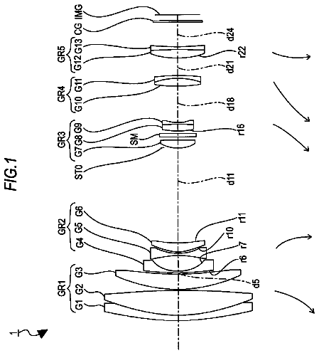
FIG. 10 is a view illustrating a longitudinal section in the first operating state of an optical system according to an Example 1 of the first embodiment.
FIG. 11 is a view illustrating the longitudinal section in the case in which the optical system shown in FIG. 10 is a wide end.
FIG. 12 is a view illustrating a longitudinal section in the second operating state of the optical system according to the Example 1 of the first embodiment.
FIG. 13 is a view illustrating the longitudinal section in the case in which the optical system shown in FIG. 12 is a wide end.
FIGS. 14A to 14C are views illustrating the zooming operation of the optical system in the first operating state of the Example 1 of the first embodiment.
FIGS. 15A to 15C are views illustrating the zooming operation of the optical system in the second operating state of the Example 1 of the first embodiment.
FIG. 16A is a view illustrating the configuration of the lateral section in the first operating state of the optical projection system of a projector according to a second embodiment, and FIG. 16B is a view illustrating the configuration of the longitudinal section in the first operating state of the optical projection system.
FIG. 17A is a view illustrating the configuration of the lateral section in the first operating state of the optical projection system of a projector according to a third embodiment, and FIG. 17B is a view illustrating the configuration of the longitudinal section in the first operating state of the optical projection system.
Description of exemplary embodiments
A projector and an optical projection system according to an embodiment of the invention will be described in detail with reference to the accompanying drawings.
First Embodiment
As shown in FIG. 1, a projector 2 according to a first embodiment of the invention forms image light PL in response to an image signal, and projects the corresponding image light PL on a surface to be projected, such as a screen SC. When the image of a liquid crystal panel 18G (18R, 18B), which is an optical modulation device embedded in the projector 2, is enlarged and then projected on the screen (the surface to be projected) SC, the optical projection system 20 of the projector 2 can make the aspect ratio AR0 of the image of the liquid crystal panel 18G (18R, 18B) different from the aspect ratio AR2 of an image to be projected on the screen SC. That is, although the aspect ratio AR0 of the display region A0 of the liquid crystal panel 18G can be different from the aspect ratio AR2 of the display region A2 of the screen SC, the aspect ratio AR0 of the display region A0 of the liquid crystal panel 18G can be the same as the aspect ratio AR2 of the display region A2 of the screen SC. In detail, the aspect ratio AR0 of the display region A0 of the liquid crystal panel 18G is, for example, 1.78:1, and the aspect ratio AR2 of the display region A2 of the screen SC is, for example, 1.78:1, 1.85:1, 2.35:1, 2.4:1, or the like.
As shown in FIG. 2, the projector 2 includes an optical system section 50 which projects image light and a circuit apparatus 80 which controls the operation of the optical system section 50.
The light source 10 of the optical system section 50 is, for example, an extra high pressure mercury lamp, and emits light including R light, G light, and B light. Here, the light source 10 may be a discharge light source other than the extra high pressure mercury lamp, and may be a solid light source, such as an LED (Light Emitting Diode) or laser. Each of a first integrator lens 11 and a second integrator lens 12 includes a plurality of lens devices which are arranged in an array. The first integrator lens 11 divides light flux received from the light source 10 into a plurality of pieces of light flux. Each of the lens devices of the first integrator lens 11 performs light condensing on the light flux received from the light source 10 in the vicinity of the lens devices of the second integrator lens 12. The lens devices of the second integrator lens 12 form the image of the lens devices of the first integrator lens 11 on the liquid crystal panels 18R, 18G, and 18B in cooperation with a superimposed lens 14. With the above-described configuration, the light from the light source 10 illuminates the whole display region (display region A0 in FIG. 1) of the liquid crystal panels 18R, 18G, and 18B with substantially uniform brightness.
A polarized conversion device 13 converts light from the second integrator lens 12 into predetermined linear polarized light. The superimposed lens 14 superimposes the images of the respective lens devices of the first integrator lens 11 on the display region of the liquid crystal panels 18R, 18G, and 18B via the second integrator lens 12.
A first dichroic mirror 15 reflects the R light which is incident from the superimposed lens 14, and passes the G light and the B light. The R light reflected by the first dichroic mirror 15 is incident on the liquid crystal panel 18R, which is the optical modulation device, via a reflection mirror 16 and a field lens 17R. The liquid crystal panel 18R forms an R-color image by modulating the R light in response to the image signal.
A second dichroic mirror 21 reflects the G light received from the first dichroic mirror 15, and passes the B light. The G light reflected by the second dichroic mirror 21 is incident on the liquid crystal panel 18G, which is the optical modulation device, via a field lens 17G. The liquid crystal panel 18G forms a G-color image by modulating G light in response to the image signal. The B light, which passed through the second dichroic mirror 21, is incident on the liquid crystal panel 18B, which is the optical modulation device, via relay lenses 22 and 24, reflection mirrors 23 and 25, and a field lens 17B. The liquid crystal panel 18B forms a B-color image by modulating the B light in response to the image signal.
A cross dichroic prism 19 is a prism for photonic synthesis. The cross dichroic prism 19 synthesizes pieces of light modulated in the respective liquid crystal panels 18R, 18G, and 18B, makes the resulting light as image light, and then progresses the resulting light to the optical projection system 20.
The optical projection system 20 enlarges and projects the image light PL, which is modulated by the liquid crystal panels 18G, 18R, and 18B and then synthesized by the cross dichroic prism 19, on the screen SC in FIG. 1. At this time, the optical projection system 20 can make the aspect ratio AR2 of the image projected on the screen SC different from the aspect ratio AR0 of the image of the liquid crystal panels 18G, 18R, and 18B, or can make the aspect ratio AR2 the same as the aspect ratio AR0.
The circuit apparatus 80 includes an image processing unit 81 to which an external image signal, such as a video signal, is input, a display drive unit 82 which drives the liquid crystal panels 18G, 18R, and 18B provided in the optical system section 50 based on the output of the image processing unit 81, a lens drive unit 83 which adjusts the state of the optical projection system 20 by operating drive mechanism (not shown) provided in the optical projection system 20, and a main control unit 88 which generally controls the operation of the circuit sections 81, 82, and 83.
The image processing unit 81 converts the input external image signal into an image signal including the grayscale or the like of each color. In the case of a first operating state in which the optical projection system 20 performs conversion of the aspect ratio of an image and then projects the image, the image processing unit 81 performs conversion in advance on the aspect ratio of an image, obtained by reversing the conversion of the aspect ratio performed by the optical projection system 20, thereby preventing the image displayed on the screen SC from being expanded and contracted in the longitudinal and lateral direction. In detail, when an image is expanded by the optical projection system 20 in the lateral direction to be in the range, for example, from 1.78:1 to 2.4:1, the image is compressed in advance in the lateral direction by 0.742=1.78/2.4 times or the image is expanded in the longitudinal direction by 1.35=2.4/1.78 times. Meanwhile, in the case of a second operating state in which the optical projection system 20 does not perform conversion of the aspect ratio or the aspect ratio of the image and projects the image, the image processing unit 81 does not perform conversion of the aspect ratio of the image as described above. In addition, the image processing unit 81 can perform various types of image processes, such as distortion correction or color correction, on the external image signal.
The display drive unit 82 can operate the liquid crystal panels 18G, 18R, and 18B based on the image signal output from the image processing unit 81, and can form an image corresponding to the relevant image signal or an image corresponding to a signal, obtained by performing an image process on the image signal, on the liquid crystal panels 18G, 18R, and 18E.
The lens drive unit 83 operates under the control of the main control unit 88, and can change the projection magnification of the image on the screen SC in FIG. 1 using the optical projection system 20 by, for example, appropriately moving a partial optical device including a diaphragm included in the optical projection system 20 along an optical axis OA. Further, the lens drive unit 83 can change the aspect ratio AR2 of the image which is projected on the screen SC in FIG. 1 by advancing and retracting additional the partial optical device, included in the optical projection system 20, on an optical axis OA, that is, on an optical path. The lens drive unit 83 can change the longitudinal position of the image which is projected on the screen SC in FIG. 1 by performing adjustment which causes the whole optical projection system 20 to be moved in the vertical direction which is perpendicular to the optical axis OA.
Hereinafter, the optical projection system 20 according to the first embodiment will be described with reference to FIG. 3A. The optical projection system 20 includes a main body section 20a which is configured by combining a plurality of optical devices, such as lenses, and drive mechanisms 61, 62, 63, and 64 which adjust the image forming state of the main body section 20a by moving a part of or the whole main body section 20a.
The main body section 20a includes a first group 30, a second group 45, a third group 60, and a diaphragm 70 in order from the side of the screen SC. In addition, the second group includes an adjustment optical device group 40 and a rotationally symmetric lens group 90 (refer to FIG. 5B or the like). The adjustment optical device group 40 can be replaced with the rotationally symmetric lens group 90. FIG. 3A illustrates a state into which the adjustment optical device group 40 is inserted. Further, FIGS. 3B and 3C respectively illustrate the display region A2 of the screen SC (refer to FIG. 1) in the first operating state into which the adjustment optical device group 40 is inserted and in the second operating state into which a rotationally symmetric lens group 90 is inserted.
The first group 30 includes a first lens unit 31 and a second lens unit 32. For example, the focus state of the main body section 20a can be adjusted by slightly moving at least one lens included in the first lens unit 31 manually along the optical axis OA. Further, the second lens unit 32 includes first, second, and third lens groups 32a, 32b, and 32c as shown in FIG. 4A. Each of the lens groups 32a, 32b, and 32c includes one or more lenses. The main body section 20a can change the projection magnification by moving the lens groups 32a, 32b, and 32c or at least one lens which is included in the lens groups 32a, 32b, and 32c along the optical axis OA using a zoom drive mechanism 61 shown in FIG. 3A.
The adjustment optical device group 40 of the second group 45 has focal distances which are different from each other in the lateral direction (X direction) and the longitudinal direction (Y direction). As a result, all the system of the optical projection system 20 including the first group 30 has focal distances which are different from each other in the longitudinal direction and the lateral direction. That is, the magnification in the longitudinal direction is different from the magnification in the lateral direction due to the main body section 20a, thereby projecting an image, having the aspect ratio AR2 which is different from the aspect ratio AR0 of the image displayed on the liquid crystal panel 18G (18R, 18B), on the screen SC. The adjustment optical device group 40 includes one or more optical devices for adjustment, which have a rotationally asymmetric surface with respect to the optical axis OA. In detail, with regard to the section in the longitudinal direction (Y direction) shown in FIG. 4B, the adjustment optical device group 40 includes a first optical device group 41 having positive power and a second optical device group 42 having negative power in order from the screen SC. In addition, the first optical device group 41 and the second optical device group 42 do not have power with regard to the section in the lateral direction (X direction) shown in FIG. 4A.
As described above, by combining the adjustment optical device group 40 which is an anamorphic optical system with the first optical device group 41 having positive refractive power and the second optical device group 42 having negative refractive power with respect to the longitudinal section, magnification can be changed easily, that is, zooming operation can be performed.
Further, in the optical projection system 20, the first anamorphic drive mechanism 62, which is an advancing and retracting drive mechanism shown in FIG. 3A, arranges the rotationally symmetric lens group 90 on the optical path instead of the adjustment optical device group 40, or arranges the adjustment optical device group 40 on the optical path instead of the rotationally symmetric lens group 90, so that it is possible to change the aspect ratio of an image to be projected on the screen SC at a desired timing.
The rotationally symmetric lens group 90 shown in FIGS. 5A and 5B, is an adjustment optical device group which has the same focal distance in the lateral direction (X direction) and the longitudinal direction (Y direction). As a result, a whole system of the optical projection system 20 which includes the first group 30 has the same focal distance in the longitudinal direction and the lateral direction. That is, the magnification in the longitudinal direction and the lateral direction is the same because of the main body section 20a, so that it is possible to project an image, which has the same aspect ratio as the aspect ratio AR0 of the image displayed on the liquid crystal panel 18G (18R, 18B), on the screen SC. The rotationally symmetric lens group 90 includes one or more optical devices for adjustment, which have a rotationally symmetric surface with respect to the optical axis OA. In detail, as shown in FIGS. 5A and 5B, in order from the side of the screen SC, the rotationally symmetric lens group 90 includes a first optical device group 91 having positive power and a second optical device group 92 having negative power. Each of the optical device groups 91 and 92 is rotationally symmetrical, so that each of the optical device groups 91 and 92 has the same power in the longitudinal direction and the lateral direction. As a result, as a whole, the rotationally symmetric lens group 90 has the same power in the longitudinal direction and the lateral direction. Further, in this case, positive power and negative power are all together at the rotationally symmetric lens group 90 and the adjustment optical device group 40, so that it is possible to comparatively easily and accurately adjust the power of each of the optical device groups 91 and 92 of the rotationally symmetric lens group 90 to a predetermined state.
As described above, in the optical projection system 20, by inserting the rotationally symmetric lens group 90 into a place where the adjustment optical device group 40 is arranged on the optical path while advancing and retracting the adjustment optical device group 40, it is possible to change the first operating state in which the adjustment optical device group 40 is placed on the optical path with the second operating state in which the rotationally symmetric lens group 90 is placed on the optical path. As shown in FIG. 6A, by using the first operating state in which the adjustment optical device group 40 is placed on the optical path, it is possible to project an image on the screen SC at an aspect ratio (for example, 2.4:1) that an image formed on the liquid crystal panel 18G (18R, 18B) is compressed in the longitudinal direction. Meanwhile, as shown in FIG. 6B, by using the second operating state in which the rotationally symmetric lens group 90 is inserted into a place where the adjustment optical device group 40 is arranged while evacuating the adjustment optical device group 40 from the optical path, it is possible to project an image on the screen SC at the aspect ratio (for example, 1.78:1) of an image formed on the liquid crystal panel 18G (18R, 18B) without change. In this case, as shown in FIG. 3B, if it is assumed that the display region in the case where the second group 45 is not installed is the display region AA, the display region AA is comparatively strongly compressed in the longitudinal direction and the display region A2, which has a shape laterally longer than that of the display region AA, is formed in the first operating state into which the adjustment optical device group 40 is inserted. Meanwhile, as shown in FIG. 3C, in the second operating state into which the rotationally symmetric lens group 90 is inserted, the display region AA is comparatively weakly compressed in both directions, that is, in the longitudinal direction and the lateral direction, and the display region A2, which has a shape similar to that of the display region AA, is formed. In addition, it is possible to move the first optical device group 41 and the second optical device group 42 which are included in the adjustment optical device group 40 in the optical axis OA direction by using the second anamorphic drive mechanism 63. By adjusting the distances between these, it is possible to continuously increase or decrease the aspect ratio of an image to be projected on the screen SC.
Further, as shown in FIG. 3A, in the optical projection system 20, by adjusting the amount of shift by moving the whole main body section 20a in the direction which is perpendicular to the optical axis OA using the entire system drive mechanism 64, the amount of deviation can be increased and decreased from the optical axis OA of the image to be projected on the screen SC. That is, by moving the optical axis OA of the main body section 20a by only an appropriate amount of shift SF with respect to the central axis AX of the liquid crystal panel 18G while maintaining the state of the optical axis OA of the main body section 20a to be parallel to the central axis AX of the liquid crystal panel 18G, the image can be projected on a position which is separated from the optical axis OA, for example, in the upper direction (+Y direction), and the projection position of the image can be vertically moved in the longitudinal direction by adjusting the amount of shift SF. In addition, the amount of shift SF, which is the amount of deviation based on the central axis AX of the liquid crystal panel 18G of the optical axis OA of the main body section 20a, is not necessarily variable, and can be fixed to, for example, a value which is not 0. Further, the whole main body section 20a can be appropriately moved in the direction along the optical axis OA using the entire system drive mechanism 64.
The description continues in the full USPTO document.
 Lapsed, fee not paid3 drawings