Technical field
This disclosure relates to tools, such as systems, apparatuses, methodologies, computer program products, etc., for providing a cloud print service.
Background
In the current digital age, the trend is that more and more tasks involve use of information technology (IT) and digital media. As an example, digital books and e-book readers are becoming very popular and are supplanting printed books and other printed publications.
In addition, enterprises (particularly, large organizations) are starting to integrate provisions in its IT environment for printing from a mainframe or application server (e.g., Oracle, SAP, etc.) on a corporate network to a printer for visitors (such as a supplier, a contractor, etc.). On the other hand, facsimile, extranet or VPN (virtual private network) connection is frequently used for communicating between a corporate office and a supplier.
However, printing remains a part of many daily tasks, such as, for example, generating, finalizing and archiving legal documents, distributing pamphlets, brochures and other marketing literature, issuing receipts at brick-and-mortar establishments, etc.
The proliferation of mobile devices (e.g., smartphones, PDAs, other handsets, tablet computers, notebook computers, etc.) has created a need for users of such devices to be able to conveniently print documents from their mobile devices to a nearby printing device, rather than having to transfer the documents onto a computer that is configured specifically to print from such printing device. Indeed, many mobile devices today lack print capabilities. Thus, for example, if a traveling businessperson wanted to print out some of the notes that he or she took on a mobile device (or an e-mail, including optionally an attachment thereof) before a meeting, he or she would have to e-mail the notes to a web-accessible e-mail address and retrieve and print the e-mail at a public print center (e.g., FedEx Kinko's, FedEx, Mail Boxes, Etc., other public print facility, etc.). On the other hand, the information may be confidential, proprietary, or other otherwise highly sensitive, in a manner that deters one from obtaining a hardcopy at a public facility (and potentially exposing such sensitive information to the public).
There remains a need for an improved method of printing that allows visitors and employees at a corporate office, or traveling businessperson, to more conveniently print from a mobile device.
Summary
This disclosure provides tools (in the form of apparatuses, methodologies and systems) for allowing users to print to a printing device from their computers or portable devices in an unconventional manner through a cloud print service provided by a print service providing apparatus.
In an aspect of this disclosure, a print service providing apparatus is configured to receive and store a print job uploaded by a user through a user interface provided to a terminal device, and send a release code associated with the print job back to the user via the terminal device, wherein the users enters the release code at a printing apparatus and retrieves a printout generated based on the print job.
In another aspect of this disclosure, a print service providing apparatus is configured to receive and store a print job uploaded by a user through a user interface provided to a terminal device through a public network, and send a release code associated with the print job back to the user via the terminal device, wherein the users enters the release code at a printing apparatus and retrieves a printout generated based on the print job.
In another aspect of the present disclosure, a print service providing apparatus is configured to receive and store a print job via a print request e-mail sent by a user, and send a reply e-mail containing a release code associated with the print job back to the user, wherein the users enters the release code at a printing apparatus and retrieves a printout generated based on the print job.
In another aspect of the present disclosure, a print service providing apparatus is configured to receive a print job along with login credentials of a user through a virtual private network that includes at least in part the Internet, authenticate the login credentials of the user, process the print job, and transmit the processed print job through the Internet to a printing device to be output to the user.
The aforementioned aspects and features enable printing service to be easily added, even if there is a network boundary (e.g., by a corporate network, extra network for visitors, etc.) between a mainframe or application server and a printer.
Brief description of the drawings
The aforementioned and other aspects, features and advantages can be better understood from the following detailed description with reference to the accompanying drawings wherein:
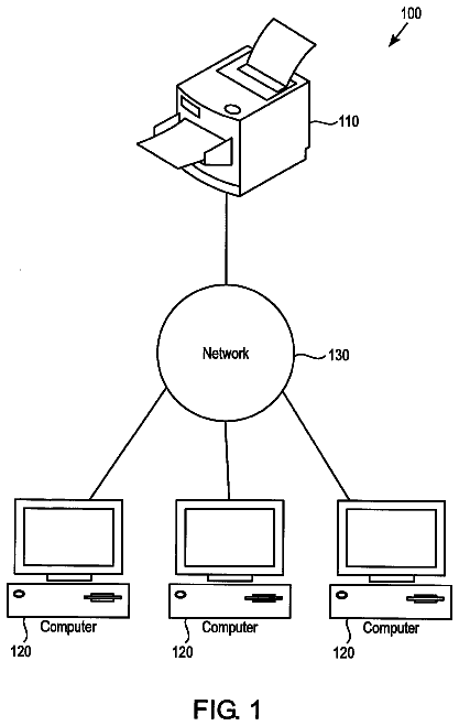
FIG. 1 shows a block diagram of a system, according to an exemplary embodiment;
FIG. 2 shows a block diagram of a system, according to another exemplary embodiment;
FIG. 3 shows a block diagram of a system, according to another exemplary embodiment;
FIG. 4 shows a block diagram of a system, according to another exemplary embodiment;
FIG. 5 shows a block diagram of an exemplary configuration of a terminal, such as in the system shown in FIG. 4;
FIG. 6 shows a block diagram of an exemplary configuration of a print device, such as in the system shown in FIG. 4;
FIG. 7 shows a flow chart for a method of providing a cloud print service, in an exemplary embodiment;
FIG. 8 shows a block diagram of a system, according to another exemplary embodiment;
FIG. 9 shows a block diagram of a system, according to another exemplary embodiment;
FIG. 10 shows a flow chart for a method of providing a cloud print service, in another exemplary embodiment;
FIG. 11 shows a block diagram of a system, according to another exemplary embodiment;
FIG. 12 shows a flow chart for a method of providing a cloud print service, in another exemplary embodiment;
FIG. 13 shows a flow chart for a method of providing a cloud print service, in another exemplary embodiment;
FIG. 14 shows a block diagram of a system, according to another exemplary embodiment;
FIG. 15 shows a flow chart for a method of authenticating user credentials, in an exemplary embodiment;
FIG. 16 shows a block diagram of a system, according to another exemplary embodiment;
FIG. 17 shows a flow chart for a method of providing a cloud print service, in another exemplary embodiment;
FIG. 18 shows a schematic representation of a workflow in the system shown in FIG. 16, in an exemplary embodiment;
FIG. 19 shows a block diagram of a system, according to another exemplary embodiment;
FIG. 20 shows a block diagram of a system, according to another exemplary embodiment;
FIG. 21A shows a block diagram of a system, according to another exemplary embodiment;
FIG. 21B shows a block diagram of a system, according to another exemplary embodiment;
FIG. 21C shows a block diagram of a system, according to another exemplary embodiment;
FIG. 22 shows a block diagram of a system, according to another exemplary embodiment;
FIG. 23 shows a block diagram of a system, according to another exemplary embodiment;
FIG. 24 shows a block diagram of a system, according to another exemplary embodiment;
FIG. 25 shows a block diagram of a system, according to another exemplary embodiment;
FIG. 26 shows a block diagram of a system, according to another exemplary embodiment;
FIG. 27 shows a block diagram of a system, according to another exemplary embodiment;
FIG. 28 shows a block diagram of a system, according to another exemplary embodiment;
FIG. 29 shows a block diagram of a system, according to another exemplary embodiment;
FIG. 30 shows a block diagram of a system, according to another exemplary embodiment;
FIG. 31 shows a block diagram of a system, according to another exemplary embodiment; and
FIG. 32 shows a block diagram of a system, according to another exemplary embodiment.
Detailed description
This disclosure provides tools (in the form of apparatuses, methodologies and systems) for allowing users to print to a printing device from their computers or portable devices in an unconventional manner through a cloud print service. Such service can be provided through a public cloud (e.g., applications delivered in a Software-as-a-Service model over the Internet, and optionally one or more types of networks, computing resources such as storage or compute cycles delivered in an infrastructure-as-a-service model, etc.) or a virtual private cloud (similar to public cloud, except that the connection is via a virtual private network through the Internet and optionally one or more types of networks), in order to take advantage of the connectivity options that are already available through the Internet.
In describing examples and exemplary embodiments illustrated in the drawings, specific terminology is employed for the sake of clarity. However, this disclosure is not intended to be limited to the specific terminology so selected and it is to be understood that each specific element includes all technical equivalents that operate in a similar manner.
In the present disclosure, the terms "corporate network" and "enterprise network" are used interchangeably. However, it should be appreciated that a corporate entity may (but is not required to) have multiple offices, and therefore the corporate network may span across multiple cities, states, countries, continents, etc. Likewise, an enterprise may (but is not required to) include multiple corporate (or other) entities, and may span across various geo-political boundaries.
Referring now to the drawings, wherein like reference numerals designate identical or corresponding parts throughout the several views, FIG. 1 shows a block diagram of a system 100, according to an exemplary embodiment of the present disclosure. The system 100 includes an employee terminal 101, a guest terminal 102, a mobile device (web/e-mail) 103, a mobile device (app) 104, a printer 105 (coupled to an external box 105a), a multi-function peripheral (MFP) 106, a shared MFP 107, MFPs 108 and 109, a printer 110 and a virtual private cloud 120.
The virtual private cloud 120 is a private cloud existing within a shared or public cloud. The resources allocated to the virtual private cloud 120 are not accessible by the public. As shown in FIG. 1, desktop & application 121, active directory (AD)/lightweight directory access protocol (LDAP) 122, a cloud print portal 123 and cloud print job storage 124 are accessible through the virtual private cloud 120. The cloud portal 123 and the cloud print job storage 124 constitute a print service providing apparatus 125 as described in the present disclosure.
The desktop & application 121 allows users to print using a virtual desktop or print from applications on the virtual private cloud 120. For example, the virtual desktop allows a user to perform tasks such as printing on the virtual private cloud 120 through a terminal acting as a thin client (i.e. the data storing and processing are performed on the servers in the cloud). The user can also access applications on the virtual private cloud 120 such as SAP or Google Docs.
The AD/LDAP 122 includes a directory service responsible for authenticating and authorizing users and computers within the network, and an application protocol used by the directory service for accessing and maintaining distributed directory information services. For example, the AD/LDAP 122 verifies the corporate domain or authenticates user login credentials (e.g., a username and a password) by communicating with the cloud print portal 123 and the cloud print job storage 124 when a print job is submitted from an office employee via the employee terminal 101.
In addition, a combination or a subset of a plurality of web servers, e-mail servers, rendering servers and file servers may be accessible through the virtual private cloud 120 and utilized to facilitate the operation of the system 100.
The cloud print portal 123 allows a user to log in and upload print jobs (e.g., documents) for printing, for example, via a web portal. The cloud print portal 123 connects to the AD/LDAP 122 to authenticate the login credentials submitted by the user. If the user is an employee, for example, connecting from the employee terminal 101, the cloud print portal 123, upon proper authentication of the user, uploads the print jobs submitted by the user to the cloud print job storage 124. For example, the print jobs are communicated to the cloud print job storage 124 utilizing a page description language (PDL) including one or more Printer Job Language (PJL) commands, in a format which can be processed by the printing device. In addition, the cloud print job storage 124 receives SAP print jobs sent from the desktop & application 121.
The employee could be using the employee terminal 101 from various locations such as his or her home, a public network, a corporate network in the corporate office, or a visitor network in the corporate office. Typically, the visitor network is accessible by the visitors of the company as well as the company employees, and in FIG. 1, the printing devices such as the printer 105, the MFP 106 and the shared MFP 107 are connected to the visitor network. In contrast, the corporate network is accessible only by the company employees, and in FIG. 1, the shared MFP 107, the MFPs 108 and 109, and the printer 110 are connected to the corporate network. Thus, the shared MFP 107, for example, can be utilized to execute print requests from both visitors and employees.
In addition to printing from applications or via a virtual desktop on the cloud or through a web portal via a browser, the user can also submit the print jobs by e-mail. When a print job is received by the cloud print portal 123, the cloud print portal 123 sends a reply e-mail including a release code to be used for retrieving a printout at one of the printers. Such a method is further discussed infra with reference to FIG. 10.
The print jobs stored in the cloud print job storage 124 can later be retrieved and printed from any of the corporate printers (i.e. the MFPs 108 and 109 and the printer 110) or the shared printers (i.e. the shared MFP 107). Such a method of printing (i.e. pull-printing) is further discussed infra with reference to FIG. 17.
The cloud print portal 123 also allows visitors, for example, connecting from the guest terminal 102, the mobile device (web/e-mail) 103 or the mobile device (app) 104, to utilize the virtual private cloud 120 to print from any of the guest printers (i.e. the printer 105 and the MFP 106) or the shared printers (i.e. the shared MFP 107). Visitors can also upload print jobs (e.g., documents) using a web portal or submit them using an e-mail client (e.g., Microsoft Outlook, Mozilla's Thunderbird or Apple's Mail) or webmail (e.g., Gmail, Yahoo! Mail or Hotmail), in a manner similar to those discussed above in connection with the case of employees.
When a print job is uploaded to the cloud print portal 123, the print job can be spooled to be rendered at a later time or immediately rendered into a printable image. Rendering servers and printer drivers accessible through the virtual private cloud facilitate such rendering operations.
Upon receiving a print job from the visiting user, the cloud print portal 123 sends a release code back to the visiting user, either through the web portal or by a reply e-mail, preferably along with an instruction for using the release code. The visiting user can then enter this release code at any of the guest printers or shared printers (e.g., the printer 105), and receive a printout of the print job submitted by the visiting user.
The printer 105, for example, is coupled to the external box 105a which facilitates the entry of the release code or login credentials by the user. Further, the external box 105a facilitates the communication between the printer 105 and the cloud print portal 123 (or the print service providing apparatus 125). The printer 105 could be manufactured by one of a variety of manufacturers, including ones unknown or unrecognized by the print service providing apparatus 125, and in such a case, the external box 105a can allow the cloud print portal 123 and the printer 105 to communicate with each other.
The system 100 illustrated in FIG. 1 represents a system that can be implemented by, for example, a typical large company which prefers to set up its own cloud.
As discussed above, the virtual private cloud 120 and the various applications and devices accessible through the virtual private cloud 120 allow employees and visitors of a corporate office, for example, to utilize the virtual private cloud 120 for printing from their terminals and mobile devices.
FIG. 2 shows a block diagram of a system 200, according to another exemplary embodiment of the present disclosure. The system 200 includes an employee terminal 201, a guest terminal 202, a mobile device (web/e-mail) 203, a mobile device (app) 204, a printer 205 (coupled to an external box 205a), a MFP 206, a shared MFP 207, MFPs 208 and 209, a printer 210 and a public cloud 220. The public cloud 220 includes desktop & application 221, a cloud print portal 222 and cloud print job storage 223. The cloud portal 222 and the cloud print job storage 223 constitute a print service providing apparatus 224 as described in the present disclosure.
The system 200 differs from the system 100 of FIG. 1 in that the system 200 is missing the AD/LDAP for authenticating users and that the system 200 has the public cloud 220 instead of the virtual private cloud 120. The public cloud 220 represents a network in which a service provider makes resources, such as applications and storage, available to the general public over the Internet. Otherwise, the operation of the system 200 is similar to that of the system 100.
The system 200 illustrated in FIG. 2 represents a system that can be implemented by, for example, a mid-sized company which would prefer to use a public cloud offered by various public cloud providers such as Amazon, Google or Microsoft.
FIG. 3 shows a block diagram of a system 300, according to another exemplary embodiment of the present disclosure. The system 300 includes an employee terminal 301, a guest terminal 302, a mobile device (web/e-mail) 303, a mobile device (app) 304, a printer 305 (coupled to an external box 305a), a MFP 306, a shared MFP 307, MFPs 308 and 309, a printer 310, a public cloud 320 and a virtual private cloud 330. The public cloud 320 includes a cloud print portal (for guests) 321. The virtual private cloud 330 includes desktop & application 331, AD/LDAP 332 and a cloud print portal & job storage 333. The cloud portal 321 constitutes a print service providing apparatus 334a, and the cloud print portal & job storage 333 constitutes a print service providing apparatus 334b, as described in the present disclosure.
The system 300 combines the system 101 of FIG. 1 and the system 200 of FIG. 2 such that guest printing is done through the public cloud 320 and employee printing is done through the virtual private cloud 330. The printing devices configured to communicate with the cloud print portal 321 (i.e. the printer 305, the MFP 306 and the shared MFP 307) are connected to the visitor network, and the printing devices configured to communicate with the cloud print portal & job storage 333 (i.e. the shared MFP 307, the MFPs 308 and the printer 310) are connected to the corporate network, as discussed with reference to FIG. 1.
Again, the shared printer 307 can be utilized to execute print requests from both visitors and corporate employees.
The system 300 illustrated in FIG. 3 represents a system that can be implemented by an organization which seeks to manage some resources in-house and provide other resources externally. This type of system allows a company to take advantage of the scalability and cost-effectiveness of a public cloud computing environment without exposing the company's critical applications and data to third-party vulnerabilities.
Some examples of how the systems of FIGS. 1-3 can be implemented for providing a cloud print service are described below with reference to FIGS. 4 through 32.
FIG. 4 shows a block diagram of a system 400 for providing a cloud print service, in an example of this disclosure. The system 400 includes a terminal 402, a print service providing apparatus 403 and a print device 404, all of which are interconnected by a network 401.
The terminal 402 can be any computing device, including but not limited to a personal, notebook or workstation computer, a kiosk, a PDA (personal digital assistant), a mobile phone or handset, another information terminal, etc., that can communicate with other devices through the network 401. Although only one user terminal is shown in FIG. 4, it should be understood that the system 400 can include a plurality of user terminal devices (which can have similar or different configurations). The terminal 402 is further described infra with reference to FIG. 5.
The network 401 can be a local area network, a wide area network or any type of network such as an intranet, an extranet (for example, to provide controlled access to external users, for example through the Internet), the Internet, etc., or a combination thereof. Further, other communications links (such as a virtual private network, a wireless link, etc.) may be used as well for the network 401. In addition, the network 401 preferably uses TCP/IP (Transmission Control Protocol/Internet Protocol), but other protocols can also be used. How devices can connect to and communicate over the network 401 is well-known in the art and is discussed for example, in "How Networks Work", by Frank J. Derfler, Jr. and Les Freed (Que Corporation 2000) and "How Computers Work", by Ron White, (Que Corporation 1999), the entire contents of each of which are incorporated herein by reference.
As indicated by the arrows between the points where the terminal 402 and the print service providing apparatus 403 are shown to connect to the network 401, the terminal 402 submits a print job to the print service providing apparatus 403 through the print service access user interface provided by the print service providing apparatus 403, and in response, the print service providing apparatus 403 sends a release code to the terminal 402. As indicated by the arrows between the points where the print device 404 and the print service providing apparatus 403 are shown to connect to the network 401, the print device 404 provides the release code to the print service providing apparatus 403 through a printer user interface provided by the print service providing apparatus 403, and in response, the print service providing apparatus 403 sends the print job to the print device 404. The operation of the system 400 is further described infra with reference to FIG. 7.
An example of a configuration of the user terminal 402 of FIG. 4 (for example, as a computer) is shown schematically in FIG. 5. In FIG. 5, computer 500 includes a controller (or central processing unit) 502 that communicates with a number of other components, including memory 503, display 504, keyboard (and/or keypad) 507, other input/output (such as mouse, touchpad, stylus, microphone and/or speaker with voice/speech interface and/or recognition software, etc.) 508, network interface 509, print driver 506 and application software 505, by way of an internal bus 501.
The memory 503 can provide storage for program and data, and may include a combination of assorted conventional storage devices such as buffers, registers and memories [for example, read-only memory (ROM), programmable ROM (PROM), erasable PROM (EPROM), electrically erasable PROM (EEPROM), static random access memory (SRAM), dynamic random access memory (DRAM), non-volatile random access memory (NOVRAM), etc.].
The network interface 509 provides a connection (for example, by way of an Ethernet connection or other network connection which supports any desired network protocol such as, but not limited to TCP/IP, IPX, IPX/SPX, or NetBEUI) to network 401.
Print driver 506 and application software 505 are shown as components connected to the internal bus 501, but in practice are typically stored in storage media such as a hard disk or portable media, and/or received through the network 401, and loaded into memory 503 as the need arises.
Depending on the type of the particular terminal device, one or more of the components shown in FIG. 5 may be missing. For example, a particular mobile phone may be missing the print driver 506 and the keyboard 507.
Additional aspects or components of the computer 500 are conventional (unless otherwise discussed herein), and in the interest of clarity and brevity are not discussed in detail herein. Such aspects and components are discussed, for example, in "How Computers Work", by Ron White (Que Corporation 1999), and "How Networks Work", by Frank J. Derfler, Jr. and Les Freed (Que Corporation 2000), the entire contents of each of which are incorporated herein by reference.
The print device 404 of FIG. 4 will now be discussed in connection with an exemplary configuration of a multi-function device (MFD) which includes a printing function (and additionally can serve as a user terminal for entering, saving and accessing electronic data) with reference to FIG. 6.
FIG. 6 shows an example of the print device 404 of FIG. 4 (or, for example, the MFDs shown in FIGS. 1-3), which can be an MFD with scanning and printing functions, and additionally can serve as a user terminal for entering, saving and accessing electronic data or documents. In addition, an MFD can include a resident database.
The MFD 600 shown in FIG. 6 includes a controller 602, and various elements connected to the controller 602 by an internal bus 601. The controller 602 controls and monitors operations of the MFD 600. The elements connected to the controller 602 include storage 603 (for example, random access memory, read-only memory, hard disk drive, portable storage media drive such as for optical discs, magnetic discs, magneto-optical discs, etc., semiconductor memory cards, combinations of storage media, etc.), printer engine 604, scanner engine 605, network interface (I/F) 606, converter 608 for converting data from one format to another format (for example, a format suitable for printing, faxing, e-mailing, etc.), and user I/O (Input/Output) 609. The controller 602 also utilizes information stored in user management table 607 to authenticate the user and control user access to the functionalities of the MFD 600.
Storage 603 can include one or more storage parts or devices, and program code instructions can be stored in one or more parts or devices of storage 603 and executed by the controller 602 to carry out the instructions. Such instructions can include instructions for performing specified functions (such as printing, scanning, faxing, copying, e-mailing, etc.) of the MFD 600, to enable the MFD 600 to interact with a terminal, as well as perhaps other external devices, through the network interface 606, and to control the converter 608, access data in the user management table 607, and interactions with users through the user I/O 609.
The network interface 606 is utilized by the MFD 600 to communicate with the print service providing apparatus (e.g., print service providing apparatus 403 of FIG. 4) and receive print jobs and user interfaces.
The user I/O 609 includes one or more display screens that display, under control of controller 602, information allowing the user of the MFD 600 to interact with the MFD 600. The display screen can be any of various conventional displays (such as a liquid crystal display, a plasma display device, a cathode ray tube display, etc.), but preferably is equipped with a touch sensitive display (for example, liquid crystal display) and is configured to provide a GUI (graphical user interface) based on information input by an operator of the MFD 600, so as to allow the operator to interact conveniently with services provided on the MFD 600, or with the MFD 600 serving as terminal for accessing electronic data or other content through the network. User interfaces or other contents received through the network via the network interface 606 can be displayed on the display screen.
The display screen does not need to be integral with, or embedded in, a housing of the MFD 600, but may simply be coupled to the MFD 600 by either a wire or a wireless connection. The user I/O 609 may include keys and/or buttons (such as graphical keys or buttons, or other graphical elements, of a GUI on a touchscreen display) for inputting information or requesting various operations. Alternatively, the user I/O 609 and the display screen may be operated by a keyboard, a mouse, a remote control, voice recognition (e.g., through a speaker/microphone 609a), or eye-movement tracking, or a combination thereof.
Since the MFD 600 is typically shared by a number of users, and is typically stationed in a common area, the MFD 600 preferably prompts the user to supply login credentials or authentication information, such as user name (or other user or group information), password, access code, etc. The login credentials or authentication information can be compared to data stored in the user management table 607 (e.g. user authentication data 607a) to confirm that the user is authorized to use the MFD 600. The login credentials or authentication information may also be stored for the session and automatically supplied if access to other devices through the network requires it. On the other hand, such other devices may prompt the user to supply other login credentials or authentication information through the user interface.
Other methods of authentication may also be used. For example, the MFD 600 may be equipped with a card reader or one or more biometrics means (such as comparing fingerprints, palm prints, voice or speech, retinas or irises, facial expressions or features, signature, etc.).
The MFD 600 may communicate the login credentials, provided in the manners discussed above, to other devices or applications connected to the MFD 600 via a network (e.g., the network 401 of FIG. 4) for print job retrieval purposes. Such a method will be discussed in greater detail in connection with FIG. 13.
Printer engine 604, scanner engine 605 and network interface 606 are otherwise conventional, and therefore, a detailed description of such conventional aspects is omitted in the interest of clarity and brevity.
The MFD 600 can have any or all of the functions of similar devices conventionally known, such as for scanning, editing and storing images, sending a fax, sending and receiving e-mails with or without attachments, accessing files by FTP or another protocol or facility, surfing the Web, etc. Further, multi-functional devices or multi-function peripheral devices can play a prominent role to convert hardcopy documents to electronic documents.
With reference to FIG. 7, a method of providing a cloud print service (utilized by, for example, the print service providing apparatus 403 of FIG. 4) is described below.
In the example shown in FIG. 7, the print service providing apparatus 403 receives and stores a print job uploaded through the print service access user interface from the terminal 402 (step S701). In return, the print service providing apparatus 403 sends a release code associated with the print job to the print service access user interface on the terminal 403 (step S702). When the release code is received from the print device 404 (S703, YES), the print service providing apparatus 403 retrieves the particular print job associated with the release code (step S704). Then, the print service providing apparatus 403 transmits the particular print job to the print device 404 (step S705).
As explained above, the printout is not generated until the release code is entered by the user (i.e. until the user is actually at the printer printing the document), thus reducing paper waste and the risk of a third-party accidentally retrieving or misappropriating the printed document.
With reference to FIG. 8, another system configuration for providing a cloud print service is described below.
System 800 of FIG. 8 includes the Internet 801, a visitor network 802, a corporate network 803, firewalls 804 and 805, a terminal 806 (including a browser application 806a), a mobile device 807 (including a mobile application 807a), a print device 808, a print service providing apparatus 809, printers 810 and 815, and MFPs 811-814.
A firewall is a device designed to permit or deny network transmissions based upon a set of rules, and is often used to protect networks from unauthorized access while permitting legitimate communications to pass.
The firewall 804 filters access requests from outside the enterprise environment (e.g., the company for which the system 800 is implemented), which includes both the visitor network 802 and the corporate network 803. The firewall 805 filters access requests from the visitor network 802 to resources on the corporate network 803.
As discussed above, the terminal 806 can be any computing device, including but not limited to a personal, notebook or workstation computer, a kiosk, a PDA (personal digital assistant), a mobile phone or handset, another information terminal, etc., that can communicate with other devices through the network.
The print service providing apparatus 809 provides a print service access user interface 806b through a network to the terminal 806, receive and store the print job uploaded through the print service access user interface 806b from the terminal 806 via the network, and send a release code associated with the print job through the network to the print service access user interface 806b on the terminal 806.
The print device 808 includes a job access user interface 808a configured for user entry of the release code. When the release code is entered by the user, the print device 808 communicates the release code to the print service providing apparatus 809. In response, the print service providing apparatus 809 sends the print job to the print device 808. Upon receiving the print job, the print device 808 processes the print job to generate a print output based on the processed print job. The generated print output is then output to the user.
The print device 808 can further include a printer-side browser 808b coupled to the job access user interface 808a for facilitating the user's request to retrieve print jobs through the visitor network 802 from the print service providing apparatus 809 and to obtain the print output of the print jobs from the print device 808.
Alternatively, the user can upload the print job to the print service providing apparatus 809 through the mobile application 807a on the mobile device 807 via the visitor network 802. In such a case, the operation of the print service providing apparatus 809 and the print device 808 is similar to that discussed above in connection with the terminal 806.
As shown in FIG. 8, the system 800 includes a plurality of printing devices. The printer 810 and the MFPs 811 and 812 are connected to the visitor network 802, and the MFPs 813 and 814 and the printer 815 are connected to the corporate network 803. Although these printing devices may all reside in the same enterprise environment (i.e. within a single company), the users of the system 800 may have varying access to these printing devices. For example, corporate employees might be permitted to print from all of the printing devices (i.e. the printers 810 and 816, and the MFPs 811-814), whereas visiting users are permitted to print from only the printing devices on the visitor network 802 (i.e. the printer 810 and the MFPs 811 and 812).
These printing devices operate in a similar manner as discussed in connection with the print device 808.
The system 800 might be used, for example, in a case that a company visitor wishes to print a document using one of the printers on the visitor network. For example, the company visitor connects his or her laptop PC or mobile device to the visitor network 802 and uploads the document he or she wishes to print using a web portal. Using the release code that is displayed in return, the company visitor can go to the nearest printer connected to the visitor network 802, enter the release code, and retrieve the printout of the document.
With reference to FIG. 9, another system configuration for providing a cloud print service is described below.
FIG. 9 shows a block diagram of a system 900 for providing a cloud print service, in another example of this disclosure. The system 900 includes a terminal device 902 (including webmail/e-mail client 902a), a print service providing apparatus 903 (including an e-mail address 903a) and a print device 904, all of which are interconnected by a network 901.
The system 900 of FIG. 9 is different from the system 400 of FIG. 4 discussed above in that the system 900 provides a cloud print service via e-mail.
As indicated by the arrows between the points where the terminal 902 and the print service providing apparatus 903 are shown to connect to the network 901, the terminal device 902 sends a print request e-mail including a print job to the print service providing apparatus 903 using webmail/e-mail client 902a, and in response, the print service providing apparatus 903 sends a reply e-mail including a release code to the terminal device 902. As indicated by the arrows between the points where the print device 904 and the print service providing apparatus 903 are shown to connect to the network 901, the print device 404 provides the release code to the print service providing apparatus 903 through a printer user interface provided by a cloud print service client provided by the print service providing apparatus 903, and in response, the print service providing apparatus 903 sends the print job to the print device 904. The operation of the system 900 is further described infra with reference to FIG. 10.
Otherwise, the operation of the terminal device 902, the print service providing apparatus 903 and the print device is similar to that discussed above in connection with the system 400 of FIG. 4.
The method of providing a cloud print service via e-mail (utilized by, for example, the print service providing apparatus 903 of FIG. 9) will be discussed below with reference to FIG. 10.
In the example shown in FIG. 10, the print service providing apparatus 903 receives a print request e-mail including a print job from the terminal 902 (step S1001). In return, the print service providing apparatus 903 sends a reply e-mail including a release code associated with the print job to the terminal 902 (step S1002).
The reply e-mail preferably includes instructions on how to use the release code. As discussed above, the user may enter the received release code at any of the plurality of printing devices that might be available as long as the user has access to the particular printing device he or she wishes to use.
When the release code is received from the print device 904 (S1003, YES), the print service providing apparatus 903 retrieves the particular print job associated with the release code (step S1004). Then, the print service providing apparatus 903 transmits the particular print job to the print device 904 to be processed and output to the user (step S1005).
With reference to FIG. 11, another system configuration for providing a cloud print service is described below.
The description continues in the full USPTO document.
 Lapsed, fee not paid3 drawings