Lapsed, fee not paid5 drawings
Chips & Semiconductors · US 8,756,800 B2
Electronic component mounting method
An electronic component mounting method is disclosed.
US 8,757,826 B2 · Assignee: Stanley Electric Co., Ltd. · Inventors: Sakai; Takaaki et al.
Sheet 1 of 18 from the published document. All sheets in the USPTO PDF
A light-emitting device having an LED element and a resin layer including a convex portion covering the LED element can suppress color unevenness to achieve light emission with uniform color distribution. The light-emitting device can include a substrate, an LED element mounted on the substrate, a resin layer which contains a wavelength conversion material and is formed on the substrate to cover the LED element, the resin layer including a convex portion directly covering the LED element and a flat thin film portion extending around the convex portion, and a reflective portion which is formed over the thin film portion around the convex portion. A diffusion portion can be formed to cover the convex portion of the resin layer.
Many light-emitting devices utilizing an LED element include a combination of an LED element and a wavelength conversion material such as a fluorescent material in order to provide light emission with desired color such as white light emission. In general, such a wavelength conversion material can be dispersed in a sealing resin for the LED element to cover the LED element therewith. In a conventional production method, a substrate on which an LED element is mounted is provided with a recessed portion (horn), on the bottom of which the LED element is mounted. Then, a fluorescent material-containing resin is filled in the recessed portion to complete a light-emitting device. In this light-emitting device, however, the optical path length from the LED element to the top surface of a portion of the resin layer immediately above the LED element may be different from the optical path length f
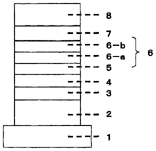
1 of 18 drawing sheets so far from the published document, cropped to the drawing. Every sheet is in the USPTO PDF.
What the patent claimed, word for word. All of it is now free to use.
This application claims the priority benefit under 35 U.S.C. .sctn.119 of Japanese Patent Application Nos. 2011-011306 filed on Jan. 21, 2011 and 2011-063002 filed on Mar. 22, 2011, which are hereby incorporated in their entirety by reference.
The presently disclosed subject matter relates to a light-emitting device utilizing an LED element, a method for producing the same and an illuminating device. In particular, the presently disclosed subject matter relates to a light-emitting device including an LED element and a resin layer formed using a compression molding method and sealing the LED element to improve the color evenness.
Many light-emitting devices utilizing an LED element include a combination of an LED element and a wavelength conversion material such as a fluorescent material in order to provide light emission with desired color such as white light emission. In general, such a wavelength conversion material can be dispersed in a sealing resin for the LED element to cover the LED element therewith. In a conventional production method, a substrate on which an LED element is mounted is provided with a recessed portion (horn), on the bottom of which the LED element is mounted. Then, a fluorescent material-containing resin is filled in the recessed portion to complete a light-emitting device.
In this light-emitting device, however, the optical path length from the LED element to the top surface of a portion of the resin layer immediately above the LED element may be different from the optical path length from the LED element to the peripheral side surface of the resin layer, resulting in color unevenness at those regions. For example, suppose a light-emitting device utilizing a combination of a blue LED element and a fluorescent material, bluish light can be observed at the area of the resin layer immediately above the LED element while yellowish light can be observed at the peripheral area of the resin layer due to the color of the light emitted from the fluorescent material.
To cope with this problem, methods for providing a hemispherical fluorescent material layer over an LED element by injecting a fluorescent material containing resin in between a mold and the LED element and curing the resin. (See, for example, Japanese Patent Application Laid-Open Nos. 2006-148147, 2008-211205, and 2010-125647.) In these methods, a compression molding method has been widely utilized as the resin molding method. Such a hemispherical fluorescent material layer can alleviate the color unevenness due to the difference in optical path lengths within the fluorescent material layer, but the effects are insufficient.
Further, in order to remove bubbles contained in the fluorescent material resin, the compression molding method may require inserting a thin releasing sheet in between a mold and a substrate on which an LED element has been mounted and perform vacuuming. As a result, the fluorescent material resin can enter the space between the substrate and the sheet, so that a thin resin layer can be formed on the surface of the substrate where the LED element has been mounted.
Accordingly, the light-emitting device produced by means of the compression molding method, in addition to the hemispherical resin layer (sometimes referred to as a hemispherical fluorescent material layer), a thin resin layer formed around the hemispherical resin layer can be formed to emit light by the excitation of the fluorescent material by the light from the LED element. Therefore, the surrounding area can be observed as being more yellowish than the hemispherical portion, resulting in color unevenness more. A light source utilizing an LED element is often used for an illuminating device or the like in combination with condensing optical components such as a lens. When light emitted from such a light source with color unevenness is projected by condensing optical components or the like, the color unevenness or color separation is made more explicit, thereby providing mostly or only uneven illumination. FIGS. 1A and 1B are a cross-sectional view of a white LED light-emitting device (light source) produced by a compression molding method, and a schematic diagram illustrating how the color separation of the projected light occurs. As shown in the drawings (in particular, see FIG. 1B), the area immediately above the LED element can be observed to be a rectangular bluish area corresponding to the shape of the element, the area surrounding the bluish area can be observed to be a white light area, and the area around the hemispherical resin layer can be observed to be a yellowish area.
To cope with this problem, after molding the resin layer, the thin resin layer around the hemispherical resin layer can be removed by sandblasting or peeled off by tape masking. However, when the thin resin layer is removed by sandblasting, the hemispherical resin layer may also be damaged at the same time. When the thin resin layer is peeled off by tape masking, the hemispherical resin layer may also be peeled off partially at the same time, resulting in decreased production yield of the light-emitting device.
The presently disclosed subject matter was devised in view of these and other problems and features and in association with the conventional art. According to an aspect of the presently disclosed subject matter, a light-emitting device can solve the problem in which the color unevenness occurs without deterioration of the production yield while achieving the generation of desired colored light with uniform distribution.
According to another aspect of the presently disclosed subject matter, a light-emitting device can intentionally utilize the light emission from a thin film portion of a resin layer around a convex portion of the resin layer so as to mix the light from the thin film portion with the light upwardly emitted by the LED element, thereby achieving the uniform light emission.
According to still another aspect of the presently disclosed subject matter, a light-emitting device can include: a substrate; an LED element mounted on the substrate; a resin layer which contains a wavelength conversion material and is formed on the substrate to cover the LED element, the resin layer including a convex portion directly covering the LED element and a flat thin film portion extending around the convex portion; and a reflective portion which is formed over the thin film portion around the convex portion.
According to still another aspect of the presently disclosed subject matter, a light-emitting device can include: a substrate; a plurality of LED elements mounted on the substrate in an array; a resin layer which contains a wavelength conversion material and is formed on the substrate to cover the plurality of LED elements; and a reflective portion which is formed over an area of the resin layer between the plurality of LED elements.
According to further another aspect of the presently disclosed subject matter, a method for producing a light-emitting device can include: mounting at least one LED element on a substrate; forming a resin layer including a convex portion covering the LED element by a compression molding method; and forming a reflective portion around the convex portion of the resin layer.
According to still further another aspect of the presently disclosed subject matter, a method for producing a light-emitting device can include: mounting at least one LED element on a substrate; forming a resin layer including a convex portion covering the LED element by a compression molding method; forming a diffusion portion covering the resin layer by using a resin containing a diffusion material; and forming a reflective portion around the convex portion of the resin layer.
According to still further another aspect of the presently disclosed subject matter, a method for producing a light-emitting device can include providing a light-shielding projection portion separating a convex portion of a resin layer covering the LED element (hemispherical resin layer) and a thin film portion of the resin layer inevitably formed therearound during the compression molding, thereby preventing the light from the LED element from entering the thin film portion of the resin layer from the convex portion thereof. The projection portion can function as part of reflector in the completed light-emitting device so that the light emitted from the convex portion of the resin layer can be even.
According to further another aspect of the presently disclosed subject matter, a method for producing a light-emitting device can include injecting a resin between a mold and a substrate where an LED element has been mounted while performing vacuuming so that a resin layer sealing the LED element is formed. The method can include mounting an LED element on a substrate; forming a light-shielding projection portion on the substrate around the LED element; and injecting a resin in between the substrate and a mold while bringing the mold into contact with the projection portion to perform a compression molding, thereby forming a resin layer.
In the method for producing a light-emitting device as described above, the step of mounting an LED element on the substrate and the step of forming a light-shielding projection portion can be performed in any order.
In the method for producing a light-emitting device as described above, the step of mounting an LED element on a substrate can include forming a reflector around an area of the substrate where the LED element is to be mounted to produce a stacked substrate, and the step of forming a projection portion can include forming a projection on the reflector.
According to still further another aspect of the presently disclosed subject matter, a light-emitting device can include: a substrate; at least one LED element mounted on the substrate; a reflector provided around the LED element; a resin layer including a convex portion covering the LED element and a thin film portion covering the reflector; and a light-shielding projection portion which is formed on the reflector and separates the convex portion and the thin film portion of the resin layer while the resin layer is not formed on the projection portion.
According to the presently disclosed subject matter, the reflective portion can be provided over the thin film portion surrounding the convex portion of the resin layer, thereby preventing the light generated in the thin film portion from being directly emitted outside. At the same time, the light can be reflected at the interface between the thin film portion and the reflective portion to be returned to the convex portion. Thereby, the color unevenness due to the generation around the convex portion can be prevented. Further, the light emitted around the convex portion and the light emitted upward from the LED element can be mixed together so that the color unevenness due to the direct light from the LED element is alleviated, achieving the uniform light emission as a whole.
According to another aspect of the presently disclosed subject matter, the projection portion can be pressed against, and brought in contact with, the mold during the compression molding. By doing so, the convex portion and the thin film portion of the resin layer can be surely separated from each other. Accordingly, in the completed light-emitting device, the light from the LED element can be prevented from entering the thin film portion through the convex portion of the resin layer as well as the thin film portion can be prevented from emitting light, whereby the light-emitting device can provide light emission with uniform color distribution.
These and other characteristics, features, and advantages of the presently disclosed subject matter will become clear from the following description with reference to the accompanying drawings, wherein:
FIGS. 1A and 1B are a cross-sectional view of a conventional LED light-emitting device produced by a compression molding method, and a diagram illustrating the color separation of the projected light from the light-emitting device of FIG. 1A, respectively;
FIGS. 2A and 2B are a plan view illustrating one example of a light-emitting device according to a first exemplary embodiment of the presently disclosed subject matter, and a cross-sectional view of the light-emitting device of FIG. 2A taken along line A-A, respectively;
FIG. 3 is a cross-sectional view of the light-emitting device according to the first exemplary embodiment together with partial enlarged view;
FIGS. 4A and 4B are diagrams each illustrating the principle of light emission from the light-emitting device of FIGS. 2A and B;
FIG. 5 includes diagrams illustrating one example of a method for producing the light-emitting device according to FIGS. 2A and B (steps a to d);
FIGS. 6A and 6B are a plan view illustrating one example of a light-emitting device according a second exemplary embodiment of the presently disclosed subject matter, and a cross-sectional view of the light-emitting device of FIG. 6A taken along line B-B, respectively;
FIG. 7 includes diagrams illustrating one example of a method for producing the light-emitting device of FIGS. 6A and B (steps a to e);
FIGS. 8A, 8B, and 8C are plan views respectively illustrating modifications of the light-emitting device of FIGS. 6A and B;
FIGS. 9A and 9B are cross-sectional views respectively illustrating modifications of the light-emitting device of FIGS. 6A and B;
FIG. 10 is a cross-sectional view illustrating a modification of the light-emitting device of FIGS. 6A and B;
FIGS. 11A and 11B are a cross-sectional view illustrating one example of a light-emitting device according to a third exemplary embodiment of the presently disclosed subject matter, and a plan view of the light-emitting device of FIG. 11A, respectively;
FIGS. 12A and 12B are diagrams illustrating examples of an illuminating device to which the presently disclosed subject matter is applied;
FIGS. 13A, 13B, 13C, 13D, and 13E are cross-sectional views each illustrating a light-emitting device as either an Example or a Comparative Example;
FIGS. 14A and 14B are a cross-sectional view and a plan view, respectively, illustrating one exemplary embodiment of a light-emitting device produced by a method for producing a light-emitting device of the presently disclosed subject matter;
FIG. 15 is a diagram illustrating the light emission status of the light-emitting device of FIGS. 14A and 14B;
FIGS. 16A and 16B are a cross-sectional view and a plan view, respectively, illustrating another exemplary embodiment of a light-emitting device produced by a method for producing a light-emitting device of the presently disclosed subject matter;
FIGS. 17A, 17B, 17C, 17D, and 17E are diagrams illustrating a fourth exemplary embodiment of a method for producing a light-emitting device of the presently disclosed subject matter;
FIGS. 18A, 18B, 18C, 18D, and 18E are diagrams illustrating a fifth exemplary embodiment of a method for producing a light-emitting device of the presently disclosed subject matter;
FIGS. 19A, 19B, 19C, and 19D are diagrams illustrating a sixth exemplary embodiment of a method for producing a light-emitting device of the presently disclosed subject matter;
FIGS. 20A and 20B are a plan view and a side view illustrating a ring-shaped member used in the production method shown in FIGS. 19A-19D; and
FIGS. 21A, 21B, 21C, and 21D are diagrams illustrating the effects of either an Example or a Comparative Example of a method for producing a light-emitting device of the presently disclosed subject matter.
A description will now be made below to light-emitting devices of the presently disclosed subject matter with reference to the accompanying drawings in accordance with exemplary embodiments.
FIGS. 2A and 2B show one example of a light-emitting device according to the present exemplary embodiment, and are a plan view illustrating the light-emitting device, and a cross-sectional view of the light-emitting device of FIG. 2A taken along line A-A, respectively.
As illustrated, the light-emitting device 10 of the present exemplary embodiment can include a substrate 11, an LED element 12, a resin layer 13, and a reflective portion 14.
The substrate 11 can be composed of a planar member formed from ceramics such as Al.sub.2O.sub.3 and AlN, glass, epoxy resin, or a metal material such as Cu and Al. The thickness thereof is not particularly limited, but may be generally about 0.4 mm to about 1.0 mm. The substrate 11 can have an electrode and/or wiring formed on a surface where the LED element is to be mounted or a rear surface so that the LED element 12 can be electrically connected to external power source although they are not illustrated in the drawings. If the substrate 11 is formed from a metal material, an insulating portion or slit may be provided to electrically insulate positive and negative electrodes.
Examples of the LED element 12 may include a face-up element having two electrode terminals on its upper surface, a flip element having two electrode terminals on its lower surface, and a metal bond (MB) element. The size of the LED element is not particularly limited, but examples of the LED element may include an element with 0.5 mm length, 0.3 mm width, and 0.12 mm thickness (relatively small element), and an element having 1 mm or more sides (relatively large element).
The resin layer 13 can include a resin, a wavelength conversion material such as a fluorescent material (phosphor), and, if required, an additive such as a filler. The types of the resin are not particularly limited as long as the resin is suitable for the compression molding method. Examples of the resin may include silicone resins, hybrid resins of epoxy and silicone, epoxy resins, and urethane resins. In terms of reliability, silicone resins are possible. In order to provide high luminance, it is possible to use a resin with a high refractive index, but such a resin with a high refractive index is generally easy to deteriorate. Accordingly, if the light-emitting device is used with higher reliability, it is possible to use a resin with a low refractive index. It should be noted that the refractive index of the resin used can be adjusted by selection of the type of the resin, the content of the filler, and the like.
The wavelength conversion material can be a material that can absorb light emitted from the LED element (be excited by the light) and emit light with wavelengths different from the absorbed light (excitation light). The types of the wavelength conversion material can be selected depending on the color of the light emission of the employed LED element, the desired color of light to be emitted, and examples thereof may include nitride or oxynitride fluorescent materials, YAG fluorescent materials, BAM fluorescent materials (aluminate type blue fluorescent material), and SiAlON fluorescent materials. For example, Y.sub.3Al.sub.5O.sub.12:Ce.sup.3+ can be used as a yellow light emission fluorescent material, Y.sub.3(Al,Ga).sub.5O.sub.12:Ce.sup.3+ can be used as a green light emission fluorescent material, and CaAlSiN.sub.3:Eu can be used as a red light emission fluorescent material.
Fillers can be used to adjust the viscosity of a sealing resin during the production process and to function as a diffusion material to reduce the color unevenness. The content of the fluorescent material and filler is not particularly limited, but in one exemplary embodiment it can be 5 to 80 wt %, and in another exemplary embodiment it can be 10 to 40 wt %, as a total content of the fluorescent material and filler with respect to the resin.
The shape of the resin layer 13 can include a substantially hemispherical convex portion 131 that can cover the LED element 13, and a thin film portion 133 disposed around the convex portion 131 and in parallel with the surface of the substrate 11.
The size of the hemispherical convex portion 131 may vary depending on the size of the LED element 13. For example, as shown in FIG. 3, when the width of the LED element 13 is D and the width of the convex portion in a direction parallel with the top surface of the LED element is W, W=D+2.times.0.6 (mm) or so. When the height of the convex portion from the top surface of the LED element is H, H=W/2 or so. For example, if the LED element has a width of 0.5 mm and a thickness of 0.12 mm, the shape of the convex portion 131 can be a hemispherical shape with a radius of 1.7 mm. By designing the shape as above, the optical path length from the light emission surface of the LED element or the upper surface thereof up to the surface of the convex portion 131 can be even.
The thickness T of the thin film portion 133 can be equal to or less than the thickness of the LED element 13, and in one exemplary embodiment it can be 0.1 mm or smaller. If the thickness of the thin film portion 133 exceeds the thickness of the LED element, the advantageous effects of the formation of the hemispherical convex portion 131 or the equalization of the optical path length may be hampered.
The reflective portion 14 can reflect light emitted from the resin layer 13 as well as can shield the light exiting outside at the interface between itself and the resin layer 13. The reflective portion 14 may be formed from a reflective material having such a function, a material totally reflecting light (such as a metal member or a mirror-finished member), or a diffusion reflection material. In particular, a diffusion reflection material, specifically a white reflection material is possible. If the reflective portion 14 is formed from a diffusion reflection material, the light generated from the thin film portion 133 of the resin layer 13 can be diffused to be directed to the convex portion 131, so that the mixing with the light directed upward from the LED element 12 can be effectively achieved as well as the production of the reflective portion 14 is facilitated.
Specifically, examples of the diffusion reflection material may include white resins prepared by mixing a white filler such as TiO.sub.2, Al.sub.2O.sub.3, AlN, SiO.sub.2, ZnO, etc. with a resin such as a silicone resin, a hybrid resin of epoxy and silicone, an epoxy resin, a urethane resin, etc. If the reflective portion 14 is formed by coating, it is possible to select a resin with an improved thixotropic property that facilitates the coating and has a favorable shape retention property after the layer formation. If the reflective portion 14 is formed by adhesion, examples of the reflective portion 14 may include white reflective plates formed from a ceramic material (Al.sub.2O.sub.3 or the like), a plastic material containing white filler (TiO.sub.2 or the like), etc.
The reflective portion 14 can be formed over the thin film portion 133 of the resin layer 13 and outside the area of the convex portion 131. The thickness t1 of the reflective portion 14 in an exemplary embodiment can be 0.2 mm or more, and in another exemplary embodiment it can be 0.5 mm or more. If the thickness t1 of the reflective portion 14 is set to 0.2 mm or more, the light from the thin film portion 133 of the resin layer 13 disposed below the reflective portion 14 can be almost completely shielded by the reflective portion 14. The reflective portion 14 can ideally be provided over the entire surface of the thin film portion 133, but is not limitative. The width d1 from the outer peripheral of the convex portion 131 can be 0.2 mm or more in one exemplary embodiment, and can be 0.5 mm or more in another exemplary embodiment. If the width d1 of the reflective portion 14 is set to 0.2 mm or more, the light from the thin film portion 133 of the resin layer 13 can be sufficiently shielded by the reflective portion 14. In addition to this, the light from the thin film portion 133 of the resin layer 13 can be reflected by the same to the convex portion of the resin layer 13, so as to mix it with the light from the LED element 12.
The reflective portion 14 is not required to be in contact with the outer periphery of the convex portion 131. As shown in the enlarged view in FIG. 3, there may be a gap 18 between the side surface of the reflective portion 14 and the outer periphery of the convex portion 131. Part of the light emitted from the thin film portion 133 of the resin layer 13 exposed to the gap 18 can be reflected by side surface of the reflective portion 14 and enter the convex portion 131 of the resin layer 13. Another part of the light can be directly mixed with the light emitted from the convex portion 131 of the resin layer 13. This can suppress the color unevenness. The allowable distance of the gap 18 may vary depending on the thickness of the convex portion 131 of the resin layer 13 and/or the thickness of the reflective portion 14, and in one exemplary embodiment it can be 0.25 mm or less.
Next, the principle of suppressed or prevented color unevenness will be described with reference to FIG. 4A. In FIG. 4A, the trajectory of light generated from the thin film portion 133 of the resin layer 13 (surrounding yellowish light) is illustrated by a dot line, and the trajectory of light directed just above the LED device 12 (rectangular bluish light area) is illustrated by a dashed line. As illustrated, the light-emitting device of the present exemplary embodiment can be configured such that the light emitted from the top surface of the LED element 12 can be diffused radially and projected with almost the same color (for example, white) due to the equal optical path length within the convex portion 131 of the resin layer 13. However, the luminance of light emitted at the center of the top surface of the LED element 12 is the maximum, and the light emission color just above the LED element may be predominantly bluish. Further, the light emitted sideward from the LED element can cause the thin film portion 133 of the resin layer 13 to emit light, and the light emission color at that area may be predominantly yellowish. In the presently disclosed subject matter, the light from the thin film portion 133 of the resin layer 13 cannot be projected directly outside (upward direction in the drawing) due to the reflective portion 14 formed thereabove. Accordingly, the light can be reflected at the interface between the thin film portion 133 of the resin layer 13 to be directed to the convex portion 133 disposed at the center of the device. Therefore, the yellowish light thus directed and the bluish light upward from the LED element 12 can be mixed together, so as to provide the resulting white light from the convex portion 133. Accordingly, the rectangular bluish light directly above the LED element 12 and the yellowish light at the surrounding area can be prevented from occurring, thereby obtaining light emission without color unevenness.
Next, the method for producing a light-emitting device of the present exemplary embodiment will be described with reference to FIG. 5.
First, an LED element 12 is fixed on a package substrate 11 by die bonding, wire bonding, or the like, so as to be electrically connected thereto (step (a)). Next, a resin material for forming the resin layer is injected into a cavity formed between the mold 40 and the substrate 11 on which the LED element 12 has been mounted by compression molding, so as to form a resin layer 13 (step (b)). When the compression molding is performed, a release sheet (not illustrated) such as a fluorinated resin sheet can be present between the mold 40 and a resin, and vacuuming is carried out during the molding of resin. In this manner, the convex portion 131 that can cover the LED element 12 and the thin film portion 133 extending around the convex portion 131 can be formed as the resin layer 13. Next, a resin coating containing a white filler can be applied around the convex portion 131 by a dispenser 41 and cured to form the reflective portion 14 (step (c)).
Alternatively, a white reflective plate can be prepared to have an opening with the same inner diameter as the outer diameter of the convex portion 13. This white reflective plate can be adhered to the thin film portion 133 while pressed by a pressurizing member 42, to form the reflective portion 14 (step (d)).
According to the principle of the presently disclosed subject matter, the reflective portion 14 covering the thin film portion 133 of the resin layer 13 can be provided around the hemispherical convex portion 131 of the resin layer 13 that covers the LED element 12. This light-emitting device can be obtained by a simple production method while the color unevenness can be prevented.
FIGS. 6A and 6B are a plan view illustrating one example of a light-emitting device according a second exemplary embodiment, and a cross-sectional view of the light-emitting device of FIG. 6A taken along line B-B. The same components as those in FIGS. 2A and 2B may be denoted by the same reference numerals.
As illustrated, the light-emitting device 10 of the present exemplary embodiment can include a substrate 11, an LED device 12, a resin layer 13, a reflective portion 140, and a diffusion layer 15.
The configuration of the substrate 11, LED device 12 and resin layer 13 is the same as the first exemplary embodiment, and the description thereof will be omitted here and a different point will be described.
Examples of the reflective portion 140 may be the same as those in the first exemplary embodiment. In the present exemplary embodiment, the reflective portion 140 can be a ring-shaped member, for example. The ring-shaped member can have an opening with an inner diameter larger than the outer diameter of the convex portion 131 so as to function as a sealing member for receiving the diffusion layer 15 between itself and the convex portion 131. The height h of the ring-shaped member in one exemplary embodiment can be half the height of the convex portion 131. The difference d2 between the inner diameter of the reflective portion 140 and the outer diameter of the convex portion 131 can be 0.25 mm or less in an exemplary embodiment.
As one example, if the height of the hemispherical convex portion 131 is 0.75 mm, the height h of the reflective portion 140 can be 0.375 mm or more. If the height and inner diameter (distance d2+the outer diameter of the convex portion 131) of the reflective portion 140 are set to fall within the above ranges, the hemispherical diffusion layer 15 can be formed to cover the convex portion 131. Further, it is possible to suppress the color unevenness due to the light emission form the thin film portion 133 of the resin layer 13 between the reflective portion 140 and the convex portion 131. The thickness (ring thickness) t2 of the reflective portion 140 as the horizontal section in one exemplary embodiment can be 0.2 mm or more. With this configuration, almost all the light emitted from the thin film portion 133 that would be a cause for the generation of color unevenness can be reflected at the interface between the thin film portion 133 and the reflective portion 140 so as to be direct to the convex portion 131.
The reflective portion 140 may be formed by coating like in the first exemplary embodiment. Or alternatively, the reflective portion 140 may be provided as a ring-shaped member formed from a ceramic material or a white filler containing plastic material by adhering it to the thin film portion 133 of the resin layer 13 via an adhesive.
The diffusion layer 15 can include a light diffusing agent, a resin material, and if required, an additive. Examples of the light diffusing agent may include fillers such as TiO.sub.2, Al.sub.2O.sub.3, AlN, SiO.sub.2, and ZnO. Examples of the resin may include silicone resins, hybrid resins of epoxy and silicone, epoxy resins, and urethane resins. In terms of its reliability, silicone resins are possible and can provide desirous qualities. The content of the filler in one exemplary embodiment can be 0.5 to 20 wt %, and in another exemplary embodiment it can be 0.5 to 10 wt %, with respect to the resin in order to achieve both the light diffusing property and the light transmitting property.
Next, the principle of suppressed or prevented color unevenness will be described with reference to FIG. 4B. In the example of FIG. 4B, the thin film portion 133 of the resin layer can emit yellowish light as in FIG. 4A. The light travelling through the inside of the resin layer 13 is the same as in FIG. 4A, and a description thereof is omitted here. Then, the light emitted from the thin film portion 133 of the resin layer 13 to the diffusion portion 15 is denoted by dotted lines. Unlike the case of FIG. 4A, the thin firm portion 133 positioned between the convex portion 131 and the reflective portion 140 is not covered with the reflective portion 140. Accordingly, the yellowish light emitted from the thin film portion 133 at that area can enter the diffusion portion 15. Thus, the light diffused by the contained light diffusing agent can be directed directly to the center of the convex portion 133 or reflected by the side surface of the reflective portion 140 while directed directly to the center of the convex portion 133, thereby mixing the light with the light from the LED element 12. Some of the light can enter the convex portion 131 to be mixed with the light from the LED element 12. Accordingly, if the diffusion portion 15 is not present, the color distribution is different at the area directly above the LED element and at the area directly above the thin film portion 133. However, such the color distribution can be averaged by the diffusion portion 15, so that a uniform color distribution can be obtained as a whole. It should be noted that the light emitted from the thin firm portion 133 and reflected at the interface between the thin film portion 133 and the reflective portion 140 can contribute to the suppression of the color unevenness as in the case of FIG. 4A.
Next, an exemplary method for producing a light-emitting device of the present exemplary embodiment will be described with reference to FIG. 7.
In the present exemplary embodiment, the step of mounting an LED element on a substrate (step a) and the step of forming a resin layer by the compression molding (step b) are the same as the method for producing the light-emitting device of the first exemplary embodiment as shown in FIG. 5. In the step of forming the reflective portion 140 (step c or step d), the reflective portion 140 can be formed to have a certain distance separated away from the outer periphery of the convex portion 131 of the resin layer 13 and a height that is half of, or higher than, the height of the convex portion 131. Then, a resin containing a diffusing agent can be injected into the closed space by the reflective portion 140, and cured to form the diffusion portion 15 covering the convex portion 131.
According to the present exemplary embodiment, in addition to the advantageous effects by the first exemplary embodiment, a further effect for eliminating the color unevenness by the diffusion portion 15 can be provided.
The present exemplary embodiment can be modified in accordance with intended purposes. FIGS. 8A, 8B, and 8C are plan views respectively illustrating modifications of the shapes of the reflective portion 140 and the diffusion portion 15, and FIGS. 9A and 9B and 10 are cross-sectional views respectively illustrating modifications of the light-emitting device.
FIGS. 8A, 8B, and 8C show modifications wherein the outer shape of the reflective portion 140 is rectangular, hexagonal, or cross-shaped (a rectangle with square cuts at its four corners), respectively.
With regard to the configurations of the modifications as shown in FIGS. 9A and 9B, the diffusion portion 15 can be formed by coating a resin containing a diffusing agent over the entire surface of the resin layer 13. Then, the reflective portion 140 can be formed to cover the diffusion portion 15 around the convex portion 151 corresponding to the convex portion 131 of the resin layer 13. Specifically, the light-emitting devices shown in FIGS. 9A and 9B can be produced by, after forming the resin layer 13 by the compression molding method and before forming the reflective portion 140 in the production method shown in FIG. 7, forming the diffusing agent-containing resin layer (diffusion portion) 15 by the compression molding method or transfer molding method. Then, with the method illustrated in step c or d of FIG. 7, the reflective portion 140 can be formed around the diffusion portion 15. Specifically, the modification of FIG. 9B is configured to include forming an upright portion 152 is formed at the peripheral edge of the diffusion portion 15 during the compression molding or transfer molding. Then, a diffusing agent-containing resin (or white filler-containing resin) can be injected in the recessed portion formed between the convex portion 151 and the upright portion 152 and cured to form the reflective portion 140. In these modifications, the formation of the reflective portion 140 can be facilitated, and be formed in close contact with the convex portion 151. Accordingly, the light from the thin film portion 133 of the resin layer 13 can be prevented from being projected directly outward as is.
FIG. 10 shows another modification in which the reflective portion 140 has a different cross-section. In the illustrated example, the reflective portion 140 can be composed of a plurality of stacked layers as a reflective member different from each other in area so that the upper reflective member has a smaller area than a lower reflective member. Accordingly, the stacked reflective member can have a tapered inside wall opened upward. This type of reflective portion 140 can be formed by repeating the step of coating a white filler-containing resin coating (like in step c of FIG. 7) or by repeating the step of adhering a white reflective plate (like in step d of FIG. 7). In the latter case, a plurality of white reflective plates with different areas so as to be sequentially stacked, or a ring-shaped white reflective member having an inclined or stepped inner surface with an upward opening can be prepared in advance and adhered to the resin layer 13. Then, like in step e of FIG. 7, the diffusing agent-containing resin can be injected in between the reflective portion 140 and the convex portion 131 and cured to form the diffusion portion 15.
Since the shape of the reflective portion 140 can be changed as above, in addition to the advantageous effects of the suppression of the color unevenness by the light reflection at the interface between the resin layer 13 and the reflective portion 140 as described above, the light distribution can be controlled by the inclination or the shape of the step of the inner wall of the reflective portion 140. Further, the reflected light from the reflective portion 140 can pass through the diffusion portion 15, to thereby suppress further the color unevenness.
The first and second exemplary embodiments are described as having a single LED element on a substrate. However, the presently disclosed subject matter is not limited thereto, and can be applied to the cases where a plurality of LED elements are mounted on a substrate, which will be described below.
The description continues in the full USPTO document.
About 6,579 words. The USPTO PDF has it with every drawing.
Fees are due 3.5, 7.5 and 11.5 years after grant. This patent expired on June 24, 2026, so the fee marked "not paid" was the one that went unpaid.
LIGHT-EMITTING DEVICE, METHOD FOR PRODUCING THE SAME, AND ILLUMINATING DEVICE
Filed Jan 2012 · published Jul 2012Light-emitting device, method for producing the same, and illuminating device
Filed Jan 2012 · granted Jun 2014Earlier publications, parents and continuations. None of them can still be enforced, or this patent would not be listed.
Prior art cited by the examiner or applicant. Useful when you check your own idea for novelty.
Everything on this page comes from the documents linked above.