Cross-reference to related applications
This application is the U.S. national phase, under 35 USC 371, of PCT/EP2010/064665, filed Oct. 1, 2010; published as WO 2011/088905A1 on Jul. 28, 2011 and claiming priority to DE 10 2010 001 014.6, filed Jan. 19, 2010, the disclosures of which are expressly incorporated herein by reference.
Field of the invention
The present invention relates to a reel changer having a device for protecting a secured area. The device extends, on either a receiving side and/or a discharge side, at least across the entire width of the reel changer and up to the end side face frames. The device includes vertical supporting frame parts along with any switch boxes and/or side boxes that are arranged directly on these frame parts. The secured area is substantially fully enclosed on one side by the reel changer and by one or more adjacent units or mechanical blocking devices and by one or more sensor-monitored access points. An operational entry by operators is possible only via the monitored access point or points.
Background of the invention
From DE 10 2007 025 800 A1, a device for protecting a hazardous area of a reel changer is known, wherein a secured area for the automatic reel loading of the reel changer extends on a receiving side and/or discharge side at least across the entire width up to the end face side frames, and is substantially delimited on one side by the reel changer and by one or more adjacent units and/or mechanical blocking devices and by one or two access points which are monitored by sensors to prevent undetected access.
From WO 2005/080241 A2 it is known to provide a zone safety device for ensuring occupational safety in the area in which large reels of material are being moved. Proposed in this case is the placement of a perimeter fence at the boundaries of a material reel storage area. To allow reels of material to be transported into or out of the storage area, a transfer lock can be provided in the zone safety device. In the transfer lock area, a preferably contactless zone safety device is proposed, which can be implemented, for example, by means of photoelectric sensors or ultrasonic sensors. Arranging sensors of these types at different heights allows complex scanning routines to be achieved, so that, for example, reels of material can pass through the transfer lock without problems, whereas an unauthorized passage through the sensor paths triggers an alarm and/or halts the movement of the material reels, in order to prevent accidents.
EP 1 986 942 A1 relates, for example, to a reel changer having a reel grille for protecting operators in the event of a core burst during operation of the printing press. A control panel for the reel changer is shown on a side frame of the reel changer. The control panel on the side frame of the reel changer is also described, for example, in EP 1 644 191 B1.
DE 295 00 873 U1 discloses an intelligent light barrier for monitoring planar secured areas. To avoid triggering an alarm or a shut-off when a "non-hazardous and pre-programmed" entry occurs, based upon the sequence in which spaced light beams are interrupted and a comparison thereof with a pattern of interruptions that are classified as non-hazardous, a scanning and comparison step prevents a triggering of the alarm or of a shut-off in the case of "non-hazardous" entries.
From DE 10 2004 038 906 A1, a method and a device for detecting moving objects in a monitoring system is known, wherein on the path of transport in front of a light barrier a detection system is provided, by means of which the object to be guided through the light barrier is identified. Passage through the light barrier is permitted based upon this identification.
DE 10 2005 030 829 A1 discloses a light barrier that is tilted in relation to vertical, wherein, on the basis of the sequential interruptions of individual light beams caused by an object passing through, information about the entry of an allowable or non-allowable object is obtained.
Summary of the invention
The problem addressed by the invention is that of providing reel changers having an improved device for protecting a secured area.
The problem is solved according to the invention by the provision of a control element for functions of the reel changer and which is located structurally separately from the reel changer and which is spaced from the side frame at a location which can be reached by an operator located outside of the secured area. The secured area, that is located on the receiving side and/or the discharge side of the reel changer, extends, on a loading side, not only up to the frame outer alignment, i.e. an alignment which continues the exterior side of the side frame on the loading side perpendicular to the reel changer axis, but from the reel changer further outward beyond the alignment of the exterior side frame. The sensor monitoring access point, which is provided on the loading side, is arranged on a side of the frame outer alignment that is distant from the reel changer, spaced laterally therefrom.
The advantages to be achieved by the invention consist particularly in that moving a control panel to a location where it can be operated from outside the secured area and/or from an extension of the secured area that includes a transfer point, at least on the reel loading side, contributes to a substantial increase in safety.
More particularly, an improved device for securing a hazardous area based upon safety mechanisms that operate in a contactless fashion is provided for the area in which reels are automatically loaded onto a reel changer, wherein said device ensures continuous protection of the secured area, even in the case of different reel diameters and during the removal of residual core containers. By "expanding" the secured area "outward", the widest range of reel sizes can be handled, without limitations resulting from stand-off distances in the case of structurally defined clearance widths (e.g., adjoining units, building walls or pillars, etc.) playing a role. The width of an access point to the secured area can then be substantially increased, for example, so as to allow clearance measurements from fixed edges to be maintained in every case. In this connection, however, a particularly high-performance safety device at the access boundaries, i.e., in the access area, is particularly advantageous.
Particularly advantageous in conjunction with a widened access point are sensor systems that enable differentiation between allowable entry and non-allowable entry through a point of access to the secured area. This also applies particularly to cases in which an allowable object, e.g., a reel, passes through, however, a person passing through the access point at the same time next to the reel is recognized as "prohibited". More particularly, in this case an embodiment is advantageous in which one sensor subsystem enables the detection of allowable entries, reels, and/or transport means, and accordingly blocks a reaction, and a second sensor subsystem is permanently "focused" and is directed toward the entry of persons, for example. For the latter sensor, in certain operational situations the reaction of the safety device with respect to an initiation of countermeasures, for example, halting movement sequences and/or shutting down a machine, can also be or is deactivated. Alternatively, a camera or camera-like device can also be provided as a sensor system, with which a detection result obtained from an evaluation unit is verified with respect to allowability.
In a particularly advantageous embodiment, the safety device has a contactless sensor system which is connected to an evaluation unit. In this case, the safety device and/or the sensor system are embodied with a light barrier, for example, which comprises a plurality of light beams extending parallel to one another. The evaluation unit detects the sequence in which the light beams are interrupted when any object is transported in and/or out, and from this can recognize a known object and in predefined cases can deactivate the safety device or parts thereof.
In an advantageous further development, in addition to a safety function the safety device also has an integrated muting function (deactivation or partial deactivation based upon the analysis of the signals of the sensor system), which saves on the expense of installing an additional device for the muting function. This muting function of the sensor system itself can be implemented in that objects can be distinguished as allowable or prohibited based upon the pattern of passage through the plurality of light beams--particularly by means of an appropriate circuit and/or implemented analysis routine. For example, it can generally be provided that--at least within a height range to be considered--only one continuous area of light beams arranged one above the other can be interrupted simultaneously. The embodiment of the allowable (loaded or unloaded) transport means is then selected accordingly. However, a person passing through cannot meet these criteria.
A so-called muting function permits a temporary deactivation of parts of the safety device or of the entire safety device. With this, the entry of objects is preferably permitted without actuating the safety device.
In the case of one preferred embodiment, the light beams are spaced evenly from one another and extend tilted in relation to horizontal, wherein in other embodiments the light beams can also be arranged extending horizontally with the surface of the light barrier tilted in relation to vertical.
At least one light beam of the light barrier, said beam extending above the known object, can advantageously be permanently active in order to detect the entry of a person or a non-allowable object into the secured area in which reels are automatically loaded onto the reel changer, even when said person or object enters the secured area together with the known object for which entry is permitted with a partially deactivated safety device (e.g., the light beams provided further below).
The known object that is allowed entry can, for example, be a material reel, a residual core container or a driverless transport vehicle.
Independently thereof, the safety device, rather than the integrated muting function or also in addition thereto, can comprise at least two photodiodes, for example, reflective photodiodes, for muting, which are connected to the evaluation unit. In a preferred embodiment, particularly four reflective photodiodes are incorporated as a muting group (two upstream of and two downstream of the light barrier). With this, objects, particularly residual core containers, can be detected based upon a reflective strip glued to the side thereof, for example, and the muting function can be activated or the safety device can be deactivated. This may be necessary particularly for the removal of the residual core containers, the shape of which is different from that of the reels. For example, if only reels are implemented in the evaluation unit as known objects (based upon the shape and the simple analysis of the sequence of interruptions of the light beams), then the muting function can be implemented on the residual core container by means of the reflective strip. Residual core containers are frequently removed using driverless transport vehicles (AGV=automatic guided vehicle). In order to pass through the secured area, these must also be equipped with reflective strips for muting, or a corresponding interruption sequence for the light beams of the light barrier must be known in the evaluation unit (internal muting), in order for the AGV to be recognized as a known object for which entry into the secured area is allowed.
To secure the protected area against the entry of persons or objects together with the known object while the sensor system is (partially) deactivated or the safety device is partially activated, the safety device can have a second, permanently active, contactless sensor subsystem that comprises at least two light beams, for example, which intersect a short distance above the known object and in their continued path pass close by the known object.
These two light beams therefore extend parallel to and spaced only a few millimeters to a few centimeters from imaginary tangents on the upper half of the known object. The lower ends of the two light beams are therefore located substantially below the upper edge of the known object and can lie close to the axial plane of the known object, depending on the selected angle of inclination.
In an advantageous further development, in addition to the sensor subsystem embodied, for example, as a light barrier, a second, permanently active, contactless sensor subsystem can be provided, whereby a reliable, permanent means for protecting a secured area can be implemented, even when the known object is a reel having a larger reel diameter. The beam path does not permit inadvertent passage over or inadvertent passage under the beams of the second safety device. Passage under the beams is possible in any case for persons moving in a severely bent position. However, even the best safety device cannot protect against all eventualities or against all deliberate circumvention. It cannot be the task of such a device to reliably prevent intentional entry in every case.
In one advantageous embodiment, a plane formed by light beams of the light barrier can be tilted in relation to a vertical plane, which extends parallel to the boundary of the access point to be secured, for example. In this manner, an object with a vertical leading edge entering in the direction of transport will interrupt the light beams successively in a continuous sequence. However, a person entering inadvertently will not do so. Minor fluctuations in vertical alignment, such as can result, for example, from winding defects, will be "compensated for" by the angular offset of adjacent light beams. In this case, the "resolution" and/or the "dimensional tolerance" can be optimized by the distance of the light beams and/or the degree of inclination.
Brief description of the drawings
Embodiment examples of the invention are illustrated in the set of drawings and will be specified in greater detail in what follows.
The drawings show:
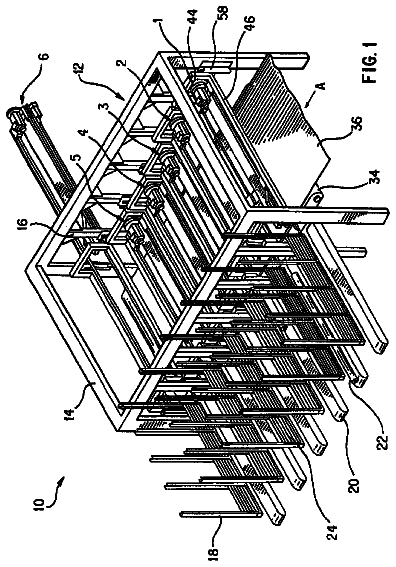
FIG. 1 a schematic front view of a reel changer;
FIG. 2 a schematic plan view of a reel changer with a secured area;
FIG. 3 embodiments of a sensor system for monitoring an access point comprising a) two sensor subsystems with parallel light beam paths, b) two sensor subsystems with horizontal and tilted light beam paths and c) two sensor systems with horizontal and tilted light beam paths;
FIG. 4 a schematic front view of a safety device comprising a light barrier;
FIG. 5 an illustration showing the arrangement of possible transmitters, receivers and sensors on opposing frame parts of an access point;
FIG. 6 illustrative schematic illustrations a) and b) for allowed and c) for prohibited objects;
FIG. 7 a perspective illustration of a reel changer with a secured area and a monitored access point;
FIG. 8 an illustration of the assembly of FIG. 7 from a different perspective;
FIG. 9 a schematic illustration of an embodiment example of the control element;
FIG. 10 a schematic illustration of a display in overview mode;
FIG. 11 a schematic illustration of a display in a screen relating to operational data about the reel changer;
FIG. 12 a subscreen for information relating to the reels located in the reel changer;
FIG. 13 a schematic illustration of a display in a screen relating to a transfer table and/or lift table;
FIG. 14 a subscreen for information relating to the reel to be handled in the area of the transfer table and/or lift table;
FIG. 15 a schematic illustration of a display in a screen relating to a reel handling and/or a reel storage and/or a reel request;
FIG. 16 a schematic illustration of a display in a subscreen that is appropriate for characterizing reel defects;
FIG. 17 a schematic illustration of a program screen on a display device of a control panel;
FIG. 18 a schematic illustration of a display in a screen relating to the reel changer status with respect to the reels and support arms.
Description of the preferred embodiment
A reel changer 01 has at least one pair of support arms 02 for supporting a reel 03, for example, material reel 03, at the end faces thereof, which pair(s) of support arms is or are mounted on a continuous or divided cross bar 06, which is mounted in end face side frames 04, for example, so as to pivot about its longitudinal axis. In this case, side frame 04 is considered to comprise, for example, all of the vertical supporting frame parts along with any switchboxes and/or side boxes that are arranged directly on these frame parts. Other adjacent units or components are preferably not included. The total width of the reel changer 01 therefore extends from exterior frame side (including any side boxes) to exterior frame side (including any side boxes). To be able to receive a reel 03 and/or release a residual reel the support arms 02 can be pivoted via the cross bar 06 by means of a drive motor, not shown. To support the reel 03, each support arm 02 is equipped with an appropriate supporting device 07, for example, a mandrel 07, which engages inside a reel core, wherein for each pair, preferably at least one mandrel, but particularly both, are positively rotationally driven--for example, by means of a drive motor 08. Preferably, the support arms 02 are embodied as positionable in the longitudinal direction of the cross bar 06 over at least one adjustment range, in order to enable, for example, a release/engagement of the mandrels 07 and/or an adjustment to different reel widths.
On a front side of the reel changer 01, e.g., a receiving and/or discharge side, a receiving and/or discharge area of the reel changer 01 is accessible to a reel 03 in order to allow a reel change thereof. In principle, a reel 03 to be received can be transported by an elevating platform truck or other transport devices to the changing position of the receiving and/or discharge area. Preferably, it is transported to a transfer table and/or lift table 09, which can be moved with at least one component that is radial in relation to the reel changer axis, with the movement of said table, for example, together with the positioning of the support arms 02, enabling a receipt or a discharge. Preferably, however, the receiving and/or discharge area is loaded with a new reel 03 using an automated (i.e., automatically moved, for example) system by means of a suitable transport means 11. This can consist of a rail-guided reel cart 11, as illustrated, which can be transported under automatic control, for example, along a transport path 10 parallel to the reel changer axis into the receiving and/or discharge area, particularly onto the transfer table and/or lift table 09, or can consist of a driverless transport system (=DTS or an AGV=automatic guided vehicle), which transports the reel 03 directly to the changing position or onto a transfer table and/or lift table 09 provided in the receiving and/or discharge area. Preferably, the process of loading a new reel 03 into the receiving and/or discharge area and/or the process of removing a discharged residual reel from the receiving and/or discharge area are carried out automatically by means of a corresponding control system. The receipt of the new reel 03 or the discharge of a residual reel by the reel changer 03 (optionally with the support of a transfer table and/or lift table 09) is then also carried out automatically, for example.
In one illustrated advantageous embodiment, a new reel 03 is transported from a storage area, not shown, to a transfer point 12 assigned to the reel changer 01 to be loaded by way of an outer loading loop. Said loop can be embodied either as manually controlled or operated transport means (e.g., forklift, rail-mounted reel cart, elevating platform truck or a combination thereof) or at least in part as driverless, automated systems (e.g., DTS, AGV, system-controlled rail-mounted reel cart or combinations thereof). At the transfer point 12, for example, the new reel 03 is then transferred to an inner loading loop, by which the reel 03 is positioned for the reel change, and by which a residual reel or core that has been removed is transported out of the reel changer area. The inner loading loop in this case comprises a rail-mounted, automatically driven reel cart 11, which can be moved from the transfer point 12 to the transfer table and/or lift table 09. The control of the transfer table and/or lift table 09 and that of the support arm movements are advantageously linked to one another by logic systems in such a way that a coordinated movement of both sides enables an automatic reel change without external intervention. Loading with new reels 03 can be carried out, for example, from a first side, e.g., from a loading side SI, to the reel changer 01. Residual reels and/or cores can be disposed of, for example, via a transport means 13 provided for this purpose (e.g., a rail-guided, particularly also automatically operable residual reel container and/or residual core container 13), on another side, for example, residual reel side SII.
Both the automatic loading with new reels 03, particularly in the inner loading loop, and the automatic reel changing process itself present substantial risk to operators located in the area. For this reason, as was described above in reference to the prior art, a plurality of safety options have already been proposed, which are intended to minimize the risk of an accident. For this purpose, for example, a secured area has already been provided directly in the area of automatic reel loading, i.e., in the receiving and/or discharge area (changing area), which is delimited on one side by mechanical blocking devices and on the other side by sensor-monitored access points.
In an embodiment illustrated in the set of figures, the risk is now reduced by the fact that operators are no longer necessarily required to enter the hazardous area, and more particularly, cannot be allowed to enter the area undetected. This is accomplished in that, on the receiving and/or discharge side of the reel changer 01, a secured area 17 is provided, which is substantially fully enclosed on one side by the reel changer 01 itself, by one or more adjoining units and/or mechanical blocking devices 14 and/or blocking element 14, for example, fences or fence sections, and by one or two sensor-monitored access points 16, in such a way that entry for operational purposes is possible only via the monitored access point or points 16. The monitored access points 16 have an access protection device or a safety device with a sensor system and with means for analyzing the sensor signals. Entry for operational purposes is understood as normal access that does not result from forceful action involving destroying or overcoming blocking measures. In contrast to the prior art, in order for the reel changer 01 to be operable without risk to operators, a control device 18, for example, a control panel 18, having at least basic control functions is provided, which is located structurally separately from the reel changer 01 in a location that is accessible to an operator who is located outside of the secured area 17. This control panel 18 is arranged not on the side frame 04 itself, but spaced therefrom, wherein, however, it is connected by means of signals to the control system and/or sensor system of the reel changer 01 and/or of the inner loading loop, for example, via corresponding cables or even wirelessly (optically or via electromagnetic radiation, such as, e.g., radio or W-LAN, etc.). In one advantageous embodiment, the control panel is arranged such that it can be reached and/or operated both from outside and from inside the secured area 17. For this purpose, it can be arranged, for example, so as to pivot such that, in one position the display 19 and/or switching and/or input means assigned to the control panel can be viewed and/or activated by an operator located outside of the secured area 17, and in another position these can be viewed and/or activated by an operator located inside of the secured area 17.
The control element 18 has, for example, at least one display 19, e.g., a display 19, which serves for indicating errors and/or for visualizing the reel changer 01 with the functionalities thereof and/or the inner loading loop. The control panel 18 further has a switch 21 used to "STOP & LOCK" the reel changer 01, optionally along with the inner loading loop, and a switch 22 for the "EMERGENCY-SHUT OFF" of the printing press or the machine section related to the reel changer 01. Additionally, keys 23 for selecting the display of the reel changer 01 and/or the reel 03 and/or the inner loading loop and/or operating or adjustment parameters that relate to reel storage, and keys 24, embodied as a block of numbers 24 (optionally with Escape, Enter, and Clear functions), for example, for modifying and/or inputting numerical values for selected parameters are preferably provided. To simplify the manipulation of screens displayed on the display 19, a cursor controller 26 or a track ball or even a computer mouse can be provided. The keys 23; 24 can be provided in a conventional configuration as individual keys (mechanical, optical, electronic), or some or all can also be provided as areas of a touch-sensitive display 19.
The control element 18 can be arranged on its own stand or on a blocking device 14, e.g., a perimeter fence 14, or on a unit adjacent to the reel changer 01. However, the control panel 18 is provided at a location that allows the operator to operate the control panel 18 while simultaneously allowing him a view into the receiving and/or discharge area of the reel changer 01.
This arrangement of an "external" operating element 18 is particularly advantageous when combined with a measure for expanding the secured area 17, particularly on the loading side SI, not only up to the side frame alignment but from the reel changer 01 or the receiving and/or discharge area thereof farther outward, and/or when combined with an access point 16 monitored by the safety device and/or the sensor system thereof, particularly on the loading side SI, not immediately in the area of the side frame alignment, but farther outward away from the reel changer 01. This expanded area of the secured area 17, extending outward beyond the alignment F of the exterior frame side, and/or the monitored access point 16, which is shifted outward, is preferably provided at least at the level of an alignment of the transport path 10. As was stated above, this expanded secured area 17 is further delimited by appropriate blocking devices 14, by the reel changer 01 itself, by any adjacent units, and optionally by an additional monitored access point 16. On an opposite side, for example, the residual reel side SII, another monitored access point 16, for example, an access point 16 that is also spaced further outward from the alignment F, can be provided.
If the exterior frame side is not formed solely by a flat wall, and instead, individual areas (e.g., individual unit attachments or stepped areas in the cover) protrude from an otherwise predominantly flat outer wall or boundary surface, for example, extending over more than 50%, particularly more than 70%, of the lateral width, the alignment F is to be understood as the horizontal direction which is perpendicular to the reel changer axis, and which continues the outer predominantly flat wall surface. This outer wall, and not individual attachments in the surface thereof, is relevant to safety in terms of a potential crushing hazard.
The description relating to the lateral expansion of the enclosed secured area 17 preferably applies in conjunction with a transfer point 12 from an outer to an inner loading loop, wherein the transfer point 12 is located at the side of the secured area 17. The monitored access point 16 then represents a type of transfer lock 16. This relative arrangement between the boundaries of the secured area 17 and the transfer point 12 prevents an accident that could result from the transfer of a reel 03 weighing a ton, for example, to the inner loading loop. If the control panel 18 is accessible from outside the secured area 17, as described above, then the risk of accidents to operators resulting from the reel transfer is also minimized. In principle, the transport path 10 of the inner loading loop can extend beyond the access point 16--in order, for example, to allow maintenance and/or adjustment of the transport means 11; 13 (e.g., fitting with adapters for smaller/larger reels) on an exterior side. Preferably, however, the transfer point 12 for reels 03 remains within the secured area 17.
If an unplanned or unauthorized entry through the monitored access point 16 is detected by the safety device or the sensor system, an error signal is preferably generated, and as a result, a pending or ongoing transfer process is broken off or a controlled interruption is at least initiated by means of corresponding signals processing via corresponding control means connected by means of signals to the inner and/or outer loading loop. An unplanned entry is understood in the broadest sense as the detection of a signal status of the sensor system which is not expressly authorized as allowable. In the simplest sense, this can be an interruption of one or more beams or acoustic waves of a system comprising one or more transmitter/detector systems arranged in the manner of a barrier. If the system in one embodiment is capable of distinguishing between a reel 03 (or reel cart 11) to be supplied and a disruption (e.g., person) that is different from this, this can be accounted for accordingly in the logic system with respect to "planned" or "allowed" and "unplanned" or "prohibited" entries (disruptions). A "planned" or allowed entry can also occur when, for example, corresponding operational situations are present, such as, for example, a shutdown of the relevant reel changer 01 or even of the machine or section.
For instance, parts of the safety device of the relevant access point 16 can preferably be deactivated, for example, for loading the reel 03, or at least a disruption caused by this can be defined as allowable.
The aforementioned safety measures are particularly advantageous when combined with sensor systems, as this ensures the most reliable possible detection of "non-allowed" entry, but does not block the desired passage of a reel 03 to be supplied or of a transport means 11; 13, for example. The sensor system--at least in part--is preferably embodied as a contactless system, for example, as a system that operates using electromagnetic or acoustic waves.
In one advantageous embodiment, the safety device has a first subsystem or a first sensor subsystem, which is deactivated, for example, with the passage of a reel 03, or at least the signal status thereof is classified as allowed or a potential reaction with respect to a reaction resulting from a change in status is blocked. These options are to be understood in what follows as a deactivation of a sensor system or of a sensor subsystem.
Additionally, the safety device has, for example, a second, permanently active, contactless subsystem or a second sensor subsystem for permanently securing the area surrounding the reel 03.
The first sensor subsystem comprises a plurality of light beams 31, e.g., two, which secure the area that can be traversed by a reel 03 or a residual reel container and/or residual core container 13, wherein the first sensor subsystem can be deactivated in order to enable entry and exit. In cases where only a reel 03 to be transported into the secured area is mentioned, the description refers similarly to a residual reel container and/or residual core container 13, a reel cart 11, or a driverless transport vehicle to be transported in, and to the inverse sequence of movements with the transport of the reel 03, a reel cart 11 or the residual reel container and/or residual core container 13 and/or the driverless transport vehicle out of the area.
The second sensor subsystem comprises, for example, a light beam 32 projecting horizontally in a first embodiment, and spaced, for example, at least 50 mm from the largest (maximum processable) reel diameter. In the case of larger reel diameters, however, a second safety device embodied in this manner has proven disadvantageous. As is clear from FIG. 3a, the hazard exists that a smaller person could enter the secured reel loading area along with the reel 03, and could thereby become injured by moving machine parts or by the moved reel 03.
FIG. 3b shows an advantageous configuration of a safety device for an automatic reel loading area. The safety device again comprises a first contactless, but deactivatable, sensor subsystem at the access boundary or at the access boundaries, i.e., at the access point 16, with two light beams 31 which protect the area that can be traversed by the reel 03 or the residual reel container and/or residual core container 13 or by the driverless transport vehicle. For constantly protecting the area surrounding the reel 03, a second, permanently active, contactless sensor subsystem is used. The second sensor subsystem comprises two light beams 32, which extend, starting from points that lie above the reel 03, past the sides of the reel 03 to an area near the floor. As is clear from FIG. 3b, a safety device embodied in this manner also does not offer adequate protection. Because the light beams 32 project past the reel 03 nearly to the floor, the hazard exists that a person walking along next to the reel 03 during loading of the reel, for example, could step over the light beams 32.
FIG. 3c shows a further advantageous embodiment of the safety device for the area of automatic reel loading, particularly with a wide access point 16, which is therefore particularly in need of protection. This safety device, in contrast to the aforementioned solutions, has, in a first sensor subsystem, a light barrier 33 having a plurality of light beams 31, e.g., more than 5, particularly more than 10, for a contactless safety device at the access boundaries of the secured automatic reel loading area. The light barrier 33 (or the "trips" thereof) can be deactivated (muted) to allow reel 03 or residual reel container and/or residual core container 13 or driverless transport vehicle to be transported in or out. A second, permanently active contactless sensor subsystem is also provided for permanently securing the area surrounding the reel 03, which system will be described further below. At this point it should be mentioned once again that access boundaries to be secured can be located not only on the loading side SI, but also opposite the loading side SI. Safety devices are to be located on both sides if both sides are freely accessible to persons. The contactless sensor system or sensor subsystem, in combination with an evaluation unit, protects the access boundary 16, i.e., the access point 16, that is to be protected by means of the light barrier 33. With a special supplementary device, described in greater detail in what follows, the first sensor subsystem can be deactivated as described above when an "allowed" object is detected.
In the embodiment example described, the light barrier 33 is formed by a plurality of light beams 31 projecting parallel to one another, for example, substantially horizontally. A transmitter 36 and a receiver 37 (e.g., FIG. 4 and FIG. 5) are assigned to the light beams 31 of the light barrier 33 and are positioned at the end points of the light beams 31. The light barrier 33 is connected to an evaluation unit, which is not shown. The evaluation unit acquires the sequence in which the light beams 31 are interrupted during the transport of a reel 03 or a residual reel container and/or residual core container 13 or a driverless transport vehicle in and/or out, and deactivates the safety device in terms of a reaction with respect to the light barrier 33 when a known object, for which access to the secured area is allowed, is detected. The evaluation unit analyzes, for example, whether the individual light beams 31 of the light barrier 33 are interrupted in succession or are again free. It is irrelevant how many or in what area the individual light beams 31 are interrupted. In general, however, gaps between interruptions of the individual light beams 31, for example, are not permissible. When a reel 03 located on a transport means 11; 13 enters, interruptions will be detected, for example, in an area from the floor up to a certain height, or in the case of "floor clearance", in an uninterrupted intermediate area. In contrast, if a person, rather than a reel 03 or a transport means 11; 13, enters, this type of criterion will not be met. The reel 03 or the transport means or the transport means 11; 13 loaded with a reel 03 should of course be configured such that in no plane of intersection, formed by the light beams 31; 32 arranged one above the other, of the transport means 11; 13 or the system of transport means 11; 13 with reel 03 does a "gap" from the lowest detectable height up to the highest detected height occur.
The description continues in the full USPTO document.
 Lapsed, fee not paid4 drawings