 Lapsed, fee not paid24 drawings
Industrial Equipment · US 8,757,335 B2
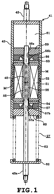
Damper, washing machine, and washer/dryer
A damper obtaining damping force by the frictional resistance imparted by the viscosity of the magnetic viscous fluid is disclosed.
US 8,757,344 B2 · Assignee: BorgWarner Inc. · Inventors: Keating; Martin P.
Sheet 1 of 4 from the published document. All sheets in the USPTO PDF
An automotive clutch housing and a method of manufacture thereof is provided. The clutch housing has a cylindrical body that is formed from a form folded strip metal sheet that is later formed into a cylindrical body. The cylindrical body is then joined to a hub to form a clutch housing.
Many, if not most, automotive clutch housings are fabricated from a cylindrical work piece. Spline teeth are then formed or cut into the cylindrical work piece. It is desirable to provide a clutch housing where the spline teeth of the clutch housing can be formed on a generally flat work piece that is later formed into a cylinder.
1 of 4 drawing sheets so far from the published document, cropped to the drawing. Every sheet is in the USPTO PDF.
What the patent claimed, word for word. All of it is now free to use.
Independent claims stand on their own. The others add detail to the claim they name.
The present invention relates to clutch housings for automotive transmissions in automotive vehicles such as, but not limited to, passenger vehicles, motor cycles, rough-terrain vehicles and trucks.
Many, if not most, automotive clutch housings are fabricated from a cylindrical work piece. Spline teeth are then formed or cut into the cylindrical work piece. It is desirable to provide a clutch housing where the spline teeth of the clutch housing can be formed on a generally flat work piece that is later formed into a cylinder.
In a preferred embodiment, the present invention provides a clutch housing that is formed from a work piece of sheet strip material. The work piece has spline teeth form folded thereon. The form folded work piece is then formed into a cylinder body and is connected with a hub portion of the clutch housing.
Further areas of applicability of the present invention will become apparent from the detailed description provided hereinafter. It should be understood that the detailed description and specific examples, while indicating the preferred embodiment of the invention, are intended for purposes of illustration only and are not intended to limit the scope of the invention.
The present invention will become more fully understood from the detailed description and the accompanying drawings, wherein:
FIG. 1 is a perspective view of a cylindrical body of A clutch housing according to the present invention;
FIG. 2 is a schematic view of a generally flat metallic sheet metal work piece utilized to form THE cylindrical body of the clutch housing of the present invention;
FIG. 3 is a schematic view of a work piece shown in FIG. 2 being form folded by press brake tooling into a cylindrical BODY for the clutch housing of the present invention;
FIG. 4 is a schematic view of an alternative fold forming operation wherein splined teeth of the cylindrical body are formed by a rolling operation;
FIG. 5 is a top view of a clutch housing of the present invention;
FIG. 6 is a sectional view taken along lines 6-6 of FIG. 5;
FIG. 7 is a perspective view of the clutch housing shown in FIG. 5;
FIG. 8 is a front perspective view of a hub utilized in the clutch housing shown in FIG. 5;
FIG. 9 is a rear perspective view of the hub shown in FIG. 8;
FIG. 10 is a front view of the hub shown in FIG. 8;
FIG. 11 is a sectional view of the hub shown in FIG. 8 taken along lines 11-11 of FIG. 10;
FIG. 12 is an enlargement of a portion that is circled in FIG. 10;
FIG. 13 is a side perspective view of the hub shown in FIG. 8; and
FIG. 14 is an enlargement of a portion 14 encircled in FIG. 13.
The following description of the preferred embodiment(s) is merely exemplary in nature and is in no way intended to limit the invention, its application, or uses.
Referring to FIG. 1, cylindrical body 410 for the clutch housing 407 (FIG. 7) according to the present invention is shown. The cylindrical body 410 is fabricated from a fold formed strip sheet metal work piece 16 (FIG. 2). Typically, steel is the material of choice. Typical cylindrical body 410 thicknesses can be approximately 1.5 mm. The cylindrical body 410 has a series of spline teeth 414. The spline teeth 414 of the cylindrical body has an inner flat 413 and an outer flat 417 that are joined by slope portions 419.
To fabricate the cylindrical body from the press brake tooling 41 is utilized having a re-hit portion 43. The press brake tooling 41 and 43 stamp the spline teeth 414 into the shape of the cylindrical body. The spline teeth 414, as schematically shown in FIG. 4, can also be roll formed from a continuous flat strip work piece 16. In a subsequent operation (not shown), an individual cylindrical body 410 is cut off.
The cylindrical body 410 has along its opposite ends, a dove tail interlock joint comprising a male tab 24 (FIG. 2) and a corresponding female cut out 26. The ends of the cylindrical body 435 and 437 are brought together to form the cylindrical shape of the cylindrical body and a connective interlock is formed by the dove tail joint 24, 26 thereafter the ends 435, 437 are joined preferably by welding, clenching or brazing.
Referring to FIGS. 5-14, a clutch housing 407 is provided. As shown, clutch housing 407 will support friction plates on its outer diameter but the clutch housing can be designed to mount friction plates on its inner diameter. Clutch housing 407 has a hub portion 440. In many embodiments, the hub 440 will be fabricated from powered metal. Hub 440 has a disc or planer portion 442 integrally connected with a cylindrical portion 444 having internal spline teeth 446. The hub 440 has a series of apertures 448 to allow for passage of rivet fasteners 450 that connects the hub 440 with the cylindrical body 410. The hub 440 along its peripheral surface has a series of radially projecting gear like teeth 451. Alternating teeth 451 have radial overhangs 452. The radial overhangs 452 are continuous with radial ribs or vanes 454 that are formed by depressions 458 in an outer surface of the hub disc portion 442. Cylindrical body spline teeth 414 have a series of axially alternating positioned oil slots 416. The cylindrical body 410 has a generally axial portion 418 and radially inwardly bent tabs 420. Between the generally axial portion 418 and the radially inwardly bent tabs 420 is a transition region 422. Between the tabs 420 within the transition region 422, there are slots 424. Connecting the generally cylindrical body 410 with the hub 440 are a series of rivets 450. The radial tabs 420 are aligned with the hub depressions 458 and the hub's radial gear like teeth 451 are aligned with the outer radial flat 417 of the spline teeth 414 of the cylindrical body 410. Additionally, the gear teeth 451 aid in supporting the spline teeth 414 in the transition region 422. The vanes 454 and their slot 424 received radial overhangs 452 provide for a circumferential interlock and torsional force transfer to the cylindrical body tabs 420. In the transition region 422, the aforementioned interlock inhibits a propagation of cracks in the cylindrical body 410.
Between the radially inward bent tabs 420 of the cylindrical housing and the disc portion 442 of the hub, there is a torsional interchange facilitated by the rivets 450 and a sheer mold. The tabs 420 lateral sides 471 have an interference fit with the vanes 454 to allow a torsional interchange in a compressive contact mode between the tabs 420 and the vanes 454. Via the overhang 458 of the vanes 454 in the slot 424, there is also a similar compressive torsional interchange between the cylindrical body and the hub in the transition region 422 of the cylindrical body. Typically the hub 440 is also connected to the cylindrical body 410 by the interference connection of the splined teeth 414 with the hub radially projecting gear like teeth 451. Accordingly, a maximum amount of torsional interchange between the hub and cylindrical body is achieved while allowing the material utilized to fabricate the cylindrical body 410 to be as thin as possible while at the same time preventing tears in the material of the cylindrical body. Torsional interchange between the hub and cylindrical body is achieved along the main portion of the radial tab 420 along the peripheral edges of the tab 420 within the transition region 422 and with the circumferential interlock between the hub gear teeth 541 and the cylindrical body splined teeth 414 providing a strong and enduring joint between the hub and cylindrical body.
The description of the invention is merely exemplary in nature and, thus, variations that do not depart from the gist of the invention are intended to be within the scope of the invention. Such variations are not to be regarded as a departure from the spirit and scope of the invention.
About 1,379 words. The USPTO PDF has it with every drawing.
Fees are due 3.5, 7.5 and 11.5 years after grant. This patent expired on June 24, 2026, so the fee marked "not paid" was the one that went unpaid.
Corrugated strip for splined clutch housing and hub
Filed Mar 2011 · published Aug 2012Corrugated strip for splined clutch housing and hub
Filed Mar 2011 · granted Jun 2014Earlier publications, parents and continuations. None of them can still be enforced, or this patent would not be listed.
Prior art cited by the examiner or applicant. Useful when you check your own idea for novelty.
Everything on this page comes from the documents linked above.


