Lapsed, fee not paid11 drawings
Hardware & Electronics · US 8,756,361 B1
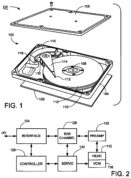
Disk drive modifying metadata cached in a circular buffer when a write operation is aborted
A disk drive is disclosed comprising a head actuated over a rotatable disk.
US 8,756,445 B2 · Assignee: Apple Inc. · Inventors: Walsh; Robert et al.
Sheet 1 of 7 from the published document. All sheets in the USPTO PDF
A portable computing device (PCD) can selectively supply power to an accessory during PCD hibernation. In some embodiments, the PCD's default behavior is to disable accessory power output during hibernation, and this default behavior can be overridden in response to a request from a connected accessory. The accessory can use the power supplied during PCD hibernation to detect user input (or other) events and wake the PCD from hibernation in response to a detected event. Some accessories can wake the PCD by emulating accessory detachment and reattachment.
The present disclosure relates generally to portable computing devices that interact with accessories and in particular to providing power from a portable device to an accessory during hibernation of the portable computing device. In recent years, a number of portable computing devices (PCDs) have been developed. Examples of PCDs include portable media players, mobile phones, personal digital assistants (PDAs), portable e-mail devices, video game players, portable navigation units relying on Global Positioning System (GPS) satellite data, and multi-function devices that can integrate numerous functions such as media storage and playback, mobile phone, Internet access, e-mail, personal information management, game play, GPS/navigation capability, and the like. Examples of multi-function PCDs include various iPhone.RTM. and iPod.RTM. models manufactured and sold by Apple Inc., assignee of
All 7 drawing sheets from the published document, cropped to the drawing.
What the patent claimed, word for word. All of it is now free to use.
The present disclosure relates generally to portable computing devices that interact with accessories and in particular to providing power from a portable device to an accessory during hibernation of the portable computing device.
In recent years, a number of portable computing devices (PCDs) have been developed. Examples of PCDs include portable media players, mobile phones, personal digital assistants (PDAs), portable e-mail devices, video game players, portable navigation units relying on Global Positioning System (GPS) satellite data, and multi-function devices that can integrate numerous functions such as media storage and playback, mobile phone, Internet access, e-mail, personal information management, game play, GPS/navigation capability, and the like. Examples of multi-function PCDs include various iPhone.RTM. and iPod.RTM. models manufactured and sold by Apple Inc., assignee of the present application, as well as other portable electronic devices made and sold by other manufactures and distributors under their respective brand names.
PCDs often obtain operating power from a battery within the device. Since a battery can provide only a finite amount of energy before requiring recharging or replacement, PCDs often employ various power-saving techniques to extend battery life. In one such technique, a PCD can be designed to transition into a "hibernation" mode in which some components of the device--such as components that consume significant fractions of the total energy (e.g., display screen, primary processor, etc.)--are powered down. Other components of the PCD can continue to receive power during hibernation, and these components generate wake-up events, or wake event signals, in response to which power is restored to the powered-down components. Thus, for example, the user can press a button on the PCD to wake it from hibernation, or a PCD can automatically wake itself from hibernation in response to an incoming phone call.
PCDs are frequently docked with other electronic devices, referred to herein as "accessories." For example, from time to time, a user may dock a PCD with a personal computer to synchronize media content and/or metadata, personal data, and the like. A user may at other times dock the same PCD with other electronic devices, such as an in-vehicle media system, a speaker dock, or the like. Some accessories may provide power to the PCD from an external source, e.g., to recharge the PCD's battery or for use as operating power, and may also use power from an external source for their own operations. Other accessories draw their operating power from the PCD.
Certain embodiments of the present invention relate to PCDs that can selectively supply power to an accessory during PCD hibernation. In some embodiments, the PCD's default behavior is to disable accessory power output during hibernation, but this default behavior can be overridden in response to a request from a connected accessory. The accessory can use the power supplied during PCD hibernation to detect user input or other events and wake the PCD from hibernation in response to a detected event. An accessory can wake the PCD, e.g., by emulating physical detachment and reattachment of the accessory.
One aspect of the invention relates to accessories for portable computing devices and methods of operation thereof. For example, an accessory can establish a connection to a portable computing device and receive operating power from the portable computing device via the connection. The accessory can communicate to the portable computing device that that the accessory should receive power from the portable computing device when the portable computing device is in a hibernation mode. While the portable computing device is hibernating, the accessory can continue to receive power from the portable computing device. The accessory can detect an "accessory event" (such as user input or any other event or circumstance that should result in waking the portable computing device), in response to which it can signal the portable computing device to wake from hibernation mode.
For example, an accessory can include an input/output (I/O) interface configured to connect to a portable computing device and to receive power from the portable computing device and a controller coupled to the I/O interface. The controller can be configured to send a request to the portable computing device to request that the accessory receive power while the portable computing device in a hibernation mode, to receive a notification from the portable computing device indicating that the portable computing device is entering the hibernation mode, to determine that the portable computing device should be awakened from the hibernation mode, and to generate a wake event signal in response to determining that the portable computing device should be awakened. For example the I/O interface can include a wake event generator, and the controller can be configured to control the wake event generator to generate the wake event signal. In some embodiments, the wake event signal can emulate detachment and reattachment of the accessory; in other embodiments, other wake event signals can be used.
In some embodiments, the portable computing device can have multiple hibernation modes, and the accessory can request to receive hibernation power in any or all of these modes. Further, in some embodiments, the accessory can also request a particular level of hibernation power for a given hibernation mode.
Another aspect of the invention relates to portable computing devices and methods of operation thereof. For example, a portable computing device can establish a connection to an accessory and provide power to the accessory, e.g., via a power pin. The portable computing device can determine whether the accessory requests hibernation power. When the portable computing device enters the hibernation mode, it can continue to provide power to the accessory if the accessory requested hibernation power or discontinue providing power to the accessory if the accessory did not request hibernation power.
For example, a portable computing device can include a processor, an accessory input/output (I/O) interface coupled to the processor and configured to connect to an accessory, and a power manager configured to deliver power from a power source to the accessory I/O interface and the processor. The power manager can be further configured to enter a hibernation mode and to return from the hibernation mode to a normal operating mode. The processor can be configured to instruct the power manager to provide power from the power source to the accessory via the accessory I/O interface and also configured to receive a request for hibernation power from the accessory via the accessory I/O interface. In response to such a request, the processor can instruct the power manager to continue to provide power to the accessory while in the hibernation mode. The power manager can be further configured such that upon entering the hibernation mode, providing of power to the accessory is discontinued unless the instruction to continue to provide power to the accessory was received prior to entering the hibernation mode.
The following detailed description together with the accompanying drawings will provide a better understanding of the nature and advantages of the present invention.
FIG. 1 is a front view of a portable computing device (PCD) according to an embodiment of the present invention.
FIGS. 2A and 2B are, respectively, a front perspective view and side view of a dock for a PCD according to an embodiment of the present invention.
FIG. 3 is a side view of a PCD docked with a dock according to an embodiment of the present invention.
FIG. 4 is a simplified block diagram of a system including a PCD connected to an accessory according to an embodiment of the present invention.
FIG. 5 is a table listing power-management commands that can be provided according to an embodiment of the present invention.
FIG. 6 is a simplified connection diagram illustrating connections that can be provided between an accessory and a PCD according to an embodiment of the present invention.
FIG. 7 is a simplified block diagram of a wake event generator for an accessory according to an embodiment of the present invention.
FIG. 8 is a flow diagram of a power management process that can be implemented in a PCD according to an embodiment of the present invention.
FIG. 9 is a flow diagram of a process that can be implemented in an accessory according to an embodiment of the present invention.
FIG. 10 is a flow diagram of a power management process that can be implemented in a PCD according to an embodiment of the present invention.
FIG. 11 is a flow diagram of a process for operating an accessory according to an embodiment of the present invention.
FIG. 12 is a block diagram of a system including a PCD connected to two accessories in a daisy chain according to an embodiment of the present invention.
Certain embodiments of the present invention relate to PCDs that can selectively supply power to an accessory during PCD hibernation. In some embodiments, the PCD's default behavior is to disable accessory power output during hibernation, but this default behavior can be overridden in response to a request from a connected accessory. The accessory can use the power supplied during PCD hibernation to detect user input or other events and wake the PCD from hibernation in response to a detected event. An accessory can wake the PCD, e.g., by emulating physical detachment and reattachment of the accessory.
FIG. 1 is a front view of a portable computing device (PCD) 100 according to an embodiment of the present invention. PCD 100 can have a touchscreen display 102 surrounded by bezel 104. Control buttons 106 are provided in bezel 104 and can be used, e.g., to wake PCD 100 from hibernation, to put PCD 100 into hibernation, or to provide other input to PCD 100.
PCD 100 can have a connector 108 recessed into a bottom surface thereof, allowing PCD 100 to become attached to an accessory device. Connector 108 can include a number of pins for carrying power, analog, and digital signals between PCD 100 and a connected accessory. In one embodiment, connector 108 can be implemented as a 30-pin docking connector as used in existing iPod.RTM. and iPhone.RTM. products sold by Apple Inc., assignee of the present application. In some embodiments, connector 108 is recessed into the housing of PCD 100 and is referred to as a "receptacle" connector. Other connectors can also be used.
As shown in inset 110, PCD 100 can have a power manager 112 and a battery 114 to provide power for the operation of PCD 100. Power manager 112 can provide power to various components of PCD 100 and to a connected accessory via connector 108. Power manager 112 can be configured to allow PCD 100 to enter a hibernation (i.e., reduced-power) mode under various conditions such as after a sufficiently long period of inactivity, thereby extending the operating life of battery 114. As described below, power manager 112 can also control whether accessory power continues to be supplied via connector 108 when PCD 100 enters the hibernation mode.
In the embodiment shown, PCD 100 can be a tablet computer with, e.g., a 10-inch screen. In other embodiments, PCD 100 can have a variety of form factors and configurations, e.g., smart phone, personal digital assistant, media player, portable web browser, etc.
FIGS. 2A and 2B are, respectively, a front perspective view and side view of a dock 200 for PCD 100 according to an embodiment of the present invention. Dock 200 has a base section 202, a keyboard 204, a PCD connector 206 and an accessory connector 208.
Base section 202 can include electronic components as well as mechanical ballast to provide stability to dock 200. Keyboard 204 can include a conventional QWERTY keyboard, numeric keypad, and/or other user input controls. Keyboard 204 can be mechanically and electrically coupled to base section 202, allowing keystroke information to be passed to PCD 100, e.g., via PCD connector 206.
PCD connector 206 can be designed to mate with connector 108 of PCD 100 of FIG. 1. For example, PCD connector 206 can be a "plug" counterpart of receptacle connector 108, extending outward from base section 202.
Accessory connector 208, shown in FIG. 2B, can be identical to connector 108 of PCD 100 of FIG. 1 and can allow an additional accessory to connect to dock 200. In this configuration, any accessory with a connector capable of connecting to connector 108 of PCD 100 can also connect to accessory connector 208 of dock 200. Use of complementary PCD connector 206 and accessory connector 208, while not required, permits another accessory to connect to PCD 100 either directly (by connecting to connector 108) or indirectly (by connecting to accessory connector 208 when connector 206 is connected to PCD 100).
In some embodiments, dock 200 need not have its own power supply. Instead, power can be provided to dock 200 by another device connected to accessory connector 208, or dock 200 can draw power from a connected PCD via connector 206.
FIG. 3 is a side view of PCD 100 docked with dock 200 according to an embodiment of the present invention. Connector 108 of PCD 100 is engaged with connector 206 of dock 200, providing electrical connections that allow power, data, and other signals to be exchanged between the two devices. Thus, for example, dock 200 can draw operating power from PCD 100. In some embodiments, as described below, dock 200 can draw operating power from PCD 100 while PCD 100 is hibernating; PCD 100 can supply this "hibernation power" to dock 200 in response to a request from dock 200.
It will be appreciated that the devices and configurations described herein are illustrative and that variations and modifications are possible. For example, as noted above, the term PCD refers generally to a broad category of personal computing and/or communication devices that can easily be carried by a user, not limited to any particular form factor or combination of capabilities.
The keyboard dock described herein is just one of many accessories that can be used with a PCD. For example, another accessory can provide a reader/writer for removable storage media such as flash memory media (e.g., Secure Digital, or "SD," cards; USB drives) or optical media (e.g., compact disc or DVD), and a PCD can be operated to direct the accessory to read data from and/or write data to the storage media. An accessory can provide output devices such as speakers and/or a display screen, allowing a user to view and/or hear content from the PCD through the accessory. A printer accessory can also be provided for printing documents or other data under control of the PCD. Still other accessories can provide enhanced functionality such as radio frequency (RF) tuners or transmitters that can be controlled by a PCD, remote user interfaces to control a PCD, still or video cameras that can be controlled by a PCD, and so on. Some accessories can provide multiple functionalities within a single device (e.g., keyboard plus storage media reader/recorder).
Further, while FIG. 3 shows PCD 100 and accessory 200 as being directly connected, indirect connections are also possible. For example, PCD 100 and accessory 200 can be connected using a cable that provides a connector complementary to connector 108 at one end and a connector complementary to connector 206 at the other end. Where a cable is used, connectors 108 and 206 need not be complementary to each other, as the cable can serve as an adapter between different connector form factors and/or pin arrangements.
FIG. 4 is a simplified block diagram of a system 400 including PCD 402 and accessory 404 according to an embodiment of the present invention. In this embodiment, PCD 402 (e.g., implementing PCD 100 of FIG. 1) can provide computing, communication and/or media playback capability. PCD 402 can include processor 410, storage device 412, user interface 414, power manager 416, network interface 418, accessory input/output (I/O) interface 420, and battery 422. PCD 402 can also include other components (not explicitly shown) to provide various enhanced capabilities.
Storage device 412 can be implemented, e.g., using disk, flash memory, or any other non-volatile storage medium. In some embodiments, storage device 412 can store media assets such as audio, video, still images, or the like, that can be played by PCD 402. Storage device 412 can also store other information such as a user's contacts (names, addresses, phone numbers, etc.); scheduled appointments and events; notes; and/or other personal information. In some embodiments, storage device 412 can store one or more application programs to be executed by processor 410 (e.g., video game programs, personal information management programs, media playback programs, etc.).
User interface 414 can include input devices such as a touch pad, touch screen, scroll wheel, click wheel, dial, button, switch, keypad, microphone, or the like, as well as output devices such as a video screen, indicator lights, speakers, headphone jacks, or the like, together with supporting electronics (e.g., digital-to-analog or analog-to-digital converters, signal processors, or the like). A user can operate input devices of user interface 414 to invoke the functionality of PCD 402 and can view and/or hear output from PCD 402 via output devices of user interface 414.
Processor 410, which can be implemented as one or more integrated circuits (e.g., a conventional microprocessor or microcontroller), can control the operation of PCD 402. In various embodiments, processor 404 can execute a variety of programs in response to program code and can maintain multiple concurrently executing programs or processes. At any given time, some or all of the program code to be executed can be resident in processor 410 and/or in storage media such as storage device 412.
Through suitable programming, processor 410 can provide various functionality for PCD 402. For example, in response to user input signals provided by user interface 414, processor 410 can operate a database engine to navigate a database of media assets stored in storage device 412 in response to user input and display lists of selected assets. Processor 410 can respond to user selection of an asset (or assets) to be played by transferring asset information to a playback engine also operated by processor 410, thus allowing media content to be played. Processor 410 can also execute other programs to control other functions of PCD 402, including application programs that may be stored in storage device 412.
Power manager 416 provides power management capability for PCD 402. For example, power manager 416 can deliver power from battery 422 to accessory I/O interface 420 via line 417 and to other components of PCD 402 (power connections not shown). Power manager 416 can also receive power via accessory I/O interface 420 and line 419 and deliver received power to various components of PCD 402; power received via accessory I/O interface 420 can also be delivered to battery 422, thereby allowing battery 422 to be recharged via accessory I/O interface 420. As shown, power manager 416 can also deliver power to accessory I/O interface 420 via line 417, allowing PCD 402 to provide power to a connected accessory. In some embodiments, power manager 416 can be implemented using programmable or controllable circuits operating in response to control signals generated by processor 410 in response to program code executing thereon, or as a separate microprocessor or microcontroller.
Power manager 416 can also control power distribution to effect a hibernation mode for PCD 402. As used herein, "hibernation" refers generally to a reduced-power operating mode (or state) that is entered by selectively powering down some components of a PCD. Power manager 416 and some components of PCD 402 can remain partially or fully operational during hibernation, allowing PCD 402 to be awakened from hibernation. During hibernation, the user's ability to interact with PCD 402 can be limited. For example, during hibernation, display screens can be turned off, and some user input controls (e.g., a touchscreen) can be disabled. One or more user input controls (e.g., a button) can remain enabled, and operation of those controls during hibernation can signal PCD 402 to wake from hibernation and return to normal operation.
Power manager 416 can also provide other power management capabilities, such as regulating power consumption of other components of PCD 402 based on the source and amount of available power, monitoring stored power in the battery and generating user alerts if the stored power drops below a minimum level, and so on.
Network interface 418 can provide voice and/or data communication capability for PCD 402. In some embodiments network interface 418 can include radio frequency (RF) transceiver components for accessing wireless voice and/or data networks (e.g., using cellular telephone technology, advanced data network technology such as 3G or EDGE, WiFi (IEEE 802.11 family standards), or other mobile communication technologies, or any combination thereof), GPS receiver components, and/or other components. In some embodiments network interface 418 can provide wired network connectivity (e.g., Ethernet) in addition to or instead of a wireless interface. Network interface 418 can be implemented using a combination of hardware (e.g., antennas, modulators/demodulators, encoders/decoders, and other analog and/or digital signal processing circuits) and software components.
Accessory I/O interface 420 can allow PCD 402 to communicate with various accessories. For example, accessory I/O interface 420 can support connections to a computer, an external keyboard (e.g., as shown in FIG. 2), a speaker dock or media playback station, a digital camera, a radio tuner (e.g., FM, AM and/or satellite), an in-vehicle entertainment system, an external video device, a memory card reader, and so on. In some embodiments, accessory I/O interface 420 can include a connector, such as a 30-pin connector corresponding to the connector used on iPod.RTM. and iPhone.RTM. products, as well as supporting circuitry. The connector can provide connections for power and ground as well as for various wired communication interfaces such as Universal Serial Bus (USB), FireWire (IEEE 1394 standard), and/or universal asynchronous receiver/transmitter (UART). The connector can also provide connections for audio and/or video signals, which may be transmitted to or from PCD 402 in analog and/or digital formats. Thus, accessory I/O interface 420 can support multiple communication channels, and a given accessory can use any or all of these channels.
Accessory I/O interface 420 can include a sensor 424 that can detect whether an accessory is connected to accessory I/O interface 420. For example, sensor 424 can detect whether a specific pin of a connector of accessory I/O interface 420 is grounded or floating, and grounding of this pin can indicate the presence of an accessory. In some embodiments, sensor 424 can measure the resistance value when a resistance is connected. The resistance value can indicate of the type of accessory connected, and sensor 424 can communicate the resistance value (or accessory-type information determined from the resistance value) to power manager 416, processor 410, and/or other components of PCD 402. In some embodiments, power manager 416 can use this information to determine, e.g., whether to distribute power from the battery or power received from accessory I/O interface 420 to other components of PCD 402, whether to use power provided via accessory I/O interface 420 to charge battery 422, whether to deliver power to accessory I/O interface 420 and so on. In some embodiments, sensor 424 can remain active during PCD hibernation and can generate signals to power manager 416 to wake PCD 402 when a new connection to an accessory is detected.
Accessory 404 (e.g., implementing dock 200 of FIG. 2) can include controller 430, user input device 432, power distribution module 434, and PCD I/O interface 436. Accessory 404 is representative of a broad class of accessories that can interoperate with a PCD, and such accessories can vary widely in capability, complexity, and form factor. Various accessories may include components not shown in FIG. 4, including but not limited to storage devices (disk, flash memory, etc.) with fixed or removable storage media; video screens, speakers, or ports for connecting to external audio/video devices; camera components such as lenses, image sensors, and controls for same (e.g., aperture, zoom, exposure time, frame rate, etc.); microphones for recording audio (either alone or in connection with video recording); and so on. In addition, some accessories may provide an additional interface that can connect to and communicate with another accessory. Some examples of accessories with additional interfaces are described in co-pending U.S. Provisional Patent Application No. 61/292,619, filed Jan. 6, 2010.
Controller 430 can include, e.g., a microprocessor or microcontroller executing program code to perform various functions associated with accessory 404. For example, where accessory 404 incorporates a keyboard (e.g., as shown in FIG. 2A), controller 430 can interpret keyboard input and send corresponding information to PCD 402.
User input device 432 may include user-operable controls such as a touch pad, touch screen, scroll wheel, click wheel, dial, button, switch, keyboard, keypad, microphone, or the like. A user can operate the controls of user input device 432 to invoke the functionality of accessory 404, and such functionality may include exchanging control signals, data, or other communications with PCD 402, e.g., as described below.
Power distribution module 434 can provide power to components of accessory 404, e.g., to controller 430 (indicated by line 435) and user input device 432 (indicated by line 437). In some embodiments, power distribution module 434 can receive power via PCD I/O interface 436 (indicated by line 439). In addition, in some embodiments, accessory 404 can be connected to an external power source via power port 440, and power from port 440 can also be provided to power distribution module 434 (indicated by line 441). Power distribution module 434 can include control logic to determine, based on the available power sources at a given time, whether to draw operating power for accessory 404 from PCD 402 or from power port 440. Further, power distribution module 434 can be configured to deliver power from power port 440 to PCD I/O interface 436 (indicated by line 443), thus allowing PCD 402 to charge battery 422 while connected to accessory 404. In some embodiments, accessory 404 can draw operating power from PCD 402 while providing charging power to PCD 402 on a separate path.
PCD I/O interface 436 can allow accessory 404 to communicate with PCD 402. In accordance with some embodiments of the invention, PCD I/O interface 436 can include a connector that mates directly with a connector included in PCD 402, such as a 30-pin connector complementary to the connector used in various iPod.RTM. and iPhone.RTM. products. Such a connector can be used to supply power to PCD 402 and/or receive power from PCD 402, to send and/or receive audio and/or video signals in analog and/or digital formats, and to communicate information using various standard interfaces such as USB, UART, and/or FireWire. Other connectors may also be used; for example, PCD I/O interface 436 can incorporate a standard USB connector and can connect to accessory I/O interface 420 of PCD 402 via an adapter cable. In other embodiments, PCD I/O interface 436 can incorporate wireless communication (e.g., using Bluetooth) with accessory I/O interface 420.
PCD I/O interface 436 can include a wake event generator 438 that can generate wake event signals for transmission to PCD 402. Any signal that results in a hibernating PCD waking can be used as a wake event signal. For example, as described above PCD 402 can be configured to wake from hibernation if an accessory becomes attached to accessory I/O interface 420. Accordingly, wake event generator 438 can open and close a connection to a pin of a connector of PCD I/O interface 436 to emulate an accessory becoming attached.
Accessory 404 can be any electronic apparatus that interacts with PCD 402, including but not limited to keyboard dock 200 as shown in FIG. 2. In some embodiments, accessory 404 can provide remote control over operations of PCD 402, or a remote user interface that can include both input and output controls (e.g., a display screen). Accessory 404 in various embodiments can control any function of PCD 402 and can also receive media content from PCD 402 and present such content to the user (e.g., through audio speakers and/or video display screen, depending on the type of media content). In other embodiments, PCD 402 can control operations of accessory 404, such as retrieving stored data from a storage medium of accessory 404, initiating an image capture operation by a camera incorporated into accessory 404, etc.
It will be appreciated that the system configurations and components described herein are illustrative and that variations and modifications are possible. The PCD and/or accessory may have other capabilities not specifically described herein (e.g., mobile phone, global positioning system (GPS), broadband data communication, Internet connectivity, etc.).
Connectors at the respective I/O interfaces of the PCD and accessory can be complementary or not as desired. Where two connectors are not complementary, an adapter can be provided to connect the two devices. While connectors may be described herein as having pins, a term generally associated with conventional electronic devices having wires to connect components, it is to be understood that other signal paths (e.g., optical signaling) can be substituted. Further, in some embodiments, some of the connections can be wireless, and connectors can be omitted where wireless interfaces are provided.
Further, while the PCD and accessory are described herein with reference to particular blocks, it is to be understood that these blocks are defined for convenience of description and are not intended to imply a particular physical arrangement of component parts. Further, the blocks need not correspond to physically distinct components. Blocks can be configured to perform various operations, e.g., by programming a processor or providing appropriate control circuitry, and various blocks might or might not be reconfigurable depending on how the initial configuration is obtained. Embodiments of the present invention can be realized in a variety of apparatus including electronic devices implemented using any combination of circuitry and software.
Accessory I/O interface 420 of PCD 402 and PCD I/O interface 436 of accessory 404 allow PCD 402 to be connected with accessory 404 and subsequently disconnected from accessory 404. As used herein, a PCD and an accessory are "connected" whenever a communication channel is established between their respective interfaces and "disconnected" when the channel is terminated. Such connection can be achieved via direct physical connection, e.g., with mating connectors; indirect physical connection, e.g., via a cable; and/or wireless connection, e.g., via Bluetooth.
In some embodiments, a PCD and an accessory can communicate while connected by exchanging commands and data according to a PCD accessory protocol, also referred to herein as an "accessory protocol." The commands and data can be communicated, e.g., using any wired or wireless transport medium provided by the relevant interfaces.
The accessory protocol defines a format for messages to be exchanged between PCD 402 and any accessories connected thereto, such as accessory 404. For instance, the accessory protocol may specify that each message (also referred to herein as a command) is sent in a packet with a header and an optional payload. The header provides basic information (e.g., a start indicator, length of the packet, and a command code identifying a command to be processed by the recipient), while the payload provides any data associated with the command; the amount of associated data can be different for different commands, and some commands may provide for variable-length payloads. In some embodiments, the commands may be defined such that any particular command code is valid in only one direction. The packet can also include error-detection or error-correction codes as known in the art.
The accessory protocol can define a number of "lingoes," where a "lingo" is a group of related commands that can be supported (or unsupported) by various classes of accessories. In one embodiment, a command code can include a first byte identifying the lingo to which the command belongs and a second byte identifying the particular command within the lingo. Other command structures may also be used. It is not required that all accessories, or all PCDs to which an accessory can be connected, support every lingo defined within the accessory protocol.
In some embodiments, every accessory 404 and every PCD 402 that use the accessory protocol support at least a "general" lingo that includes commands common to the PCD and all accessories. The general lingo can include commands enabling the PCD and the accessory to identify and authenticate themselves to each other and to provide general information about their respective capabilities, including which (if any) other lingoes each supports. The general lingo can also include authentication commands that the PCD can use to verify the purported identity and capabilities of the accessory (or vice versa), and the accessory (or PCD) may be blocked from invoking certain (or all) commands or lingoes if the authentication is unsuccessful.
A PCD accessory protocol can also include various other lingoes, such as a simple remote lingo that allows an accessory to send a command indicating a function of the PCD to be invoked, a remote user interface lingo that can be used to communicate commands and data related to replicating all or part of a user interface of a PCD on an accessory (thereby supporting a more advanced remote control), a tuner lingo that allows a user to control a tuner accessory by operating the PCD and/or to control a tuner in the PCD by operating an accessory, a storage lingo that allows an accessory to store data on the PCD, and so on. Any lingo or combination of lingoes or other commands or groups of commands can be included in an accessory protocol.
In some embodiments, the accessory protocol can include commands related to power management. FIG. 5 is a table 500 listing power-management commands that can be provided according to an embodiment of the present invention.
A HibPowerRequest command can be sent from accessory 404 to PCD 402 in order to request that PCD 402 provide power to accessory 404 during PCD hibernation. (Power provided by a PCD to an accessory during PCD hibernation is referred to herein as "hibernation power.") In some embodiments, the request for hibernation power can be incorporated into an identification command that accessory 404 can send to PCD 402 to indicate its identity and preferences. In some embodiments, hibernation power can be either requested or not, and a payload is not required; PCD 402 can infer from the absence of a request for hibernation power that hibernation power should not be provided to the accessory.
In other embodiments, accessory 404 can specify a desired hibernation power level, which can be, e.g., lower than the normal operating power; for instance, the maximum current can be reduced while holding the voltage constant. For example, accessory 404 can draw just enough power during PCD hibernation to generate a wake event signal to PCD 402. Thus, accessory 404 can contribute to power savings by drawing minimal power when PCD 402 is hibernating. In other embodiments, accessory 404 can simply reduce its power consumption during PCD hibernation without specifying a desired hibernation power level. In still other embodiments, accessory 404 can draw more power during PCD hibernation than during normal operation.
In some embodiments, PCD 402 can support multiple hibernation modes, allowing optimized power consumption under varying conditions, and the payload of the HibPowerRequest command can include an identifier of one or more particular hibernation modes during which PCD 402 should supply hibernation power; in some embodiments, delivery of power during all hibernation modes can be selected, e.g., by not identifying a particular mode. In some embodiments where multiple hibernation modes are present, accessory 404 can request different power levels for different hibernation modes, e.g., by including appropriate parameters in the HibPowerRequest command. In some embodiments, an accessory can send a new HibPowerRequest command at any time to change its preferences regarding hibernation power.
A HibNotify command can be sent from PCD 402 to accessory 404 in order to notify accessory 404 that PCD 402 is entering hibernation. In embodiments where PCD 402 supports multiple hibernation modes, the payload of the HibNotify command can include an identifier of the particular hibernation mode being entered. Where only one hibernation mode is supported, the payload of the HibNotify command can be empty. Accessory 404 can use the HibNotify command to determine whether to generate wake event signals. In addition, the HibNotify command may trigger accessory 404 to reduce its own power consumption.
It will be appreciated that the commands shown in FIG. 5 are illustrative and that variations and modifications are possible. In some embodiments, a command can be provided to allow an accessory to register its preference for receiving or not receiving HibNotify commands. In other embodiments, the PCD can be configured such that any accessory that sends a HibPowerRequest command receives subsequent HibNotify commands, or the PCD can simply send a HibNotify command to any connected accessory to indicate that the PCD is entering hibernation, and the accessory can act on or ignore the command according to its particular configuration. In some embodiments, the PCD can send a WakeNotify command to a connected accessory upon exiting hibernation; in other embodiments, waking from hibernation can include reconnecting with accessories, in which case a WakeNotify command is not used.
As noted above, accessory I/O interface 420 of PCD 402 and PCD I/O interface 436 of accessory 404 can each include a connector, and the two connectors can be complementary. FIG. 6 is a simplified connection diagram illustrating connections that can be provided between complementary connectors of an accessory and a PCD according to an embodiment of the present invention. Accessory-side connector 604 can be part of PCD I/O interface 436 of accessory 404 of FIG. 4, and PCD-side connector 602 can be part of accessory I/O interface 420 of PCD 402 of FIG. 4. In some embodiments, features of PCD-side connector 602 can be incorporated, e.g., into connector 108 of FIG. 1, and features of accessory-side connector 604 can be incorporated, e.g., into connector 208 of FIG. 2B.
In this example, PCD-side connector 602 provides a number of pins 610. (Herein, multiple instances of like objects are denoted with reference numbers identifying the object and parenthetical numbers identifying the instance where needed.) These pins can include a number of ground (GND) pins 610(1), 610
and 610(10); serial receive (RX) and transmit (TX) pins 610(2), 610
The description continues in the full USPTO document.
About 6,360 words. The USPTO PDF has it with every drawing.
Fees are due 3.5, 7.5 and 11.5 years after grant. This patent expired on June 17, 2026, so the fee marked "not paid" was the one that went unpaid.
PROVIDING POWER TO AN ACCESSORY DURING PORTABLE COMPUTING DEVICE HIBERNATION
Filed Jun 2010 · published Jul 2011Providing power to an accessory during portable computing device hibernation
Filed Jun 2010 · granted Jun 2014Earlier publications, parents and continuations. None of them can still be enforced, or this patent would not be listed.
Prior art cited by the examiner or applicant. Useful when you check your own idea for novelty.
Everything on this page comes from the documents linked above.