Lapsed, fee not paid7 drawings
Telecom & Networks · US 8,750,323 B2
Method for switching data and structure for switching data
A method and structure for switching data is provided.
US 8,750,328 B2 · Assignee: Tekelec Global, Inc. · Inventors: Sprague; David Michael et al.
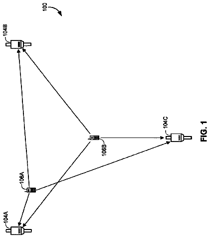
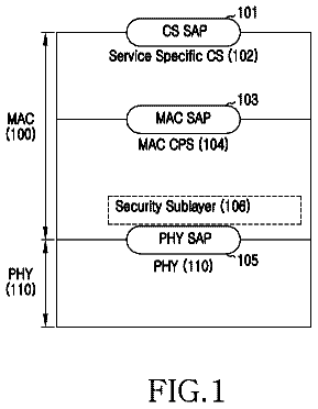
Sheet 1 of 18 from the published document. All sheets in the USPTO PDF
Methods and systems for transmitting user part messages between signaling system seven (SS7) signaling points over an internet protocol (IP) network include receiving, at a signal transfer point, a first SS7 user part message. The first SS7 user part message can be received from a first SS7 signaling point, such as a service switching point (SSP). The first SS7 signaling point is encapsulated in a first IP packet. The first IP packet is transmitted to a second SS7 signaling point over an IP network.
Modern telecommunications networks generally include two separate communication pathways or subnetworks. The first is a voice network that handles the transmission of voice or other information between users. The second is a signaling network that facilitates the dynamic linking of a plurality of voice network circuits, such that a voice-type connection is established between a calling party and a called party. These functions are generically referred to as call setup and call tear down. Additionally, the signaling network provides a framework through which non-voice related information can be transported in a manner that is transparent to the user. This signaling technique is often referred to as "out of band" signaling, where the term "band" implies voice band. Common examples of such out of band data transport are the access of 800 number database services, calling card verification s
1 of 18 drawing sheets so far from the published document, cropped to the drawing. Every sheet is in the USPTO PDF.
What the patent claimed, word for word. All of it is now free to use.
The present invention relates generally to methods and systems for communicating signaling system 7 (SS7) user part messages among SS7 nodes and internet protocol (IP) nodes. More particularly, the present invention relates to methods and systems for communicating SS7 user part messages among SS7 signaling points and IP nodes using signal transfer points (STPs).
Modern telecommunications networks generally include two separate communication pathways or subnetworks. The first is a voice network that handles the transmission of voice or other information between users. The second is a signaling network that facilitates the dynamic linking of a plurality of voice network circuits, such that a voice-type connection is established between a calling party and a called party. These functions are generically referred to as call setup and call tear down. Additionally, the signaling network provides a framework through which non-voice related information can be transported in a manner that is transparent to the user. This signaling technique is often referred to as "out of band" signaling, where the term "band" implies voice band. Common examples of such out of band data transport are the access of 800 number database services, calling card verification services, number portability services, and caller ID services.
In order to provide consistent and reliable communication across the signaling network infrastructure, a common or standard digital signaling protocol known as SS7 has been developed. SS7 is an out of band common channel signaling system that uses labeled messages to transport circuit related signaling information, non-circuit related signaling information, network resident database service information and other information that can be used for the establishment of communication services.
From a hardware perspective, an SS7 network includes a plurality of SS7 nodes, generically referred to as signaling points (SPs), that are interconnected using signaling links, also referred to as SS7 links. At least three types of SPs are provided in an SS7 network: service switching points (SSPs), signal transfer points (STPs), and service control points (SCPs).
An SSP is normally installed in tandem or Class 5 offices. The SSP is capable of handling both in-band signaling and SS7 signaling. An SSP can be a customer switch, an end-office, an access tandem and/or a tandem. An STP transfers signaling messages from one signaling link to another. STPs are packet switches and are generally installed in mated pairs. Finally, SCPs control access to databases, such as 800 number translation databases, 800 number carrier identification databases, credit card verification databases, etc.
Signaling datalinks are transmission facilities used to connect SPs together. They are dedicated bidirectional facilities operating at 56 kbps in the U.S. and Canada and at 64 kbps when clear channel capability is deployed. Normally, every link has a mate for redundancy and enhanced network integrity.
Signaling datalinks include access links or "A" links that connect SSPs to STPs and that connect SCPs to STPs, as shown in FIG. 1. Bridge links or "B" links are used to connect mated STPs to other mated STPs that are at the same hierarchical level, as shown in FIG. 2. Cross links or "C" links connect mated STPs together, as shown in FIG. 3. C links are used for passing messages between STPs when signaling network failures are encountered.
Diagonal links or "D" links connect STPs of different hierarchical levels, as shown in FIG. 4. Extended links or "E" links connect SSPs to STPs that are not within their associated local STP area, as shown in FIG. 5. Finally, fully associated links or "F" links connect SSPs directly together without STPs, as shown in FIG. 6. FIG. 7 is a block diagram of a two-level SS7 network including a summary of possible link deployment.
SS7 also includes a network protocol. As a protocol, SS7 defines a hierarchy or structure of the information contained in a message or data packet that is transmitted between SPs of an SS7 network over signaling links. This internal data structure is often referred to as an SS7 protocol stack which includes the following four SS7 levels:
Level 1: The Physical Level
Level 2: The Datalink (or Link) Level
Level 3: The Network Level
Level 4: User Parts and Application Parts Level
The physical level, also referred to as message transfer part (MTP) level 1, is the lowest or most fundamental level and is the first level that is used to interpret and process an incoming message. This level determines and/or provides the electrical characteristics to transmit the digital data over the interface being used. Following interpretation/processing at the physical level, the incoming message is passed up the stack to the datalink level.
The datalink level, also referred to as MTP level 2, resides adjacent and above the physical level and is responsible for providing error detection/correction and properly sequenced delivery of SS7 message packets. Following interpretation/processing at the datalink level, the incoming message is passed up the stack to the network level.
The network level, also referred to as MTP level 3, resides adjacent and above the datalink level and provides the information necessary for message packet routing, message packet discrimination, and message packet distribution. Functionally, message discrimination determines whether the message packet is addressed to the receiving SP or to another SP. If the message contains the local address of the receiving SP, then the message is passed on to message distribution. Message distribution routes the message to the proper application part or user part within the receiving SP. If the message is not addressed to the receiving SP, then it is passed on to the message router, which determines the physical address of the SP to which the message is to be sent. Following interpretation/processing at the network level, the incoming message is passed up the stack to the user parts and application parts level.
The user parts and application parts level resides adjacent and above the network level. User part protocols perform call setup and tear down. Exemplary user part protocols that can be included in SS7 level 4 are ISDN user part (ISUP), telephone user part (TUP), and broadband ISDN user part (BISUP).
Application part protocols provide access to network databases for services, such as 800 number service, credit card verification, and number portability. The transaction capabilities application part (TCAP) protocol is an example of an SS7 level 4 protocol that can be used to provide access to these and other services.
The above description has assumed that an incoming message is being processed. An outgoing message is passed through the protocol stack in the opposite direction, entering at the user part level and exiting from the physical level. FIG. 8 illustrates SS7 protocol architecture relative to SS7 levels and relative to standard Open System Integration (OSI) layers.
The above-mentioned SS7 protocol levels are implemented by hardware and software residing in SS7 signaling points, such as signal transfer points (STPs). A high performance STP is marketed by the assignee of the present application as the Eagle.RTM. STP. A block diagram of a conventional Eagle.RTM. STP is shown in FIG. 9. A detailed description of the Eagle.RTM. STP can be found in the Eagle.RTM. Feature Guide PN/9110-1225-01, Rev. B, January 1998, published by Tekelec, the disclosure of which is hereby incorporated herein by reference. As described in this publication, Eagle.RTM. STP generally designated 900 includes the following subsystems: maintenance and administration subsystem (MAS) 910, communication subsystem 920 and application subsystem 930. MAS 910 provides maintenance communications, initial program load, peripheral services, alarm processing and system disks. Communication subsystem 920 includes an interprocessor message transport (IMT) bus that is the main communication bus among all subsystems in Eagle.RTM. STP 900. This high speed communications system functions as two 125 Mbps counter-rotating serial buses.
Application subsystem 930 includes application cards that are capable of communicating with the other cards through the IMT buses. The illustrated application subsystem 930 includes three types of application cards: link interface module (LIM) 940 that provides SS7 links and X.25 links, application communication module (ACM) 950 that provides a TCP/IP interface for sending copies of SS7 message signal units (MSUs) over ethernet, and application service module (ASM) 960 that provides global title translation, gateway screening and other services. A translation service module (TSM) can also be provided for local number portability.
LIM 940 provides level 1 and some level 2 functions on SS7 signaling links. ACM 950 provides access to a remote host for an STP LAN feature. The STP LAN feature provides unidirectional access to copies of SS7 MSUs from the STP to a remote host. Unidirectional connection from the STP to a host is provided through an ethernet LAN using TCP/IP protocol. Finally, ASM 960 provides additional memory that is used to store translation tables and screening data. A detailed description of the Eagle.RTM. STP is provided in the above-cited Feature Guide and need not be further described.
A brief conceptual overview of the Eagle.RTM. STP is provided in the brochure entitled Eagle.RTM. STP Platform, Publication 908-0126-01, Rev. A, Tekelec, 1997. As described therein, the Eagle.RTM. STP is a high capacity, fully fault tolerant packet switch and self-contained local area network for exchanging data messages between a half-dozen to several hundred or more message processing modules. In the Eagle.RTM. STP system architecture, three functionally specific application subsystems access each other via a communications subsystem which includes dual counter-rotating, 125 Mbps IMT buses. The application subsystems include LIMs that provide SS7 and X.25 access to telecommunication signaling networks, ACMs that provide TCP/IP access to local area networks and a MAS that provides maintenance communication, peripheral services alarm processing and system disks. As stated in this brochure, "ACMs communicate directly with external, collocated service application systems via a TCP/IP, 10 Mbit/sec LAN interface mounted on the Ethernet Interface Applique (EIA). Examples of external application systems include: an SCP not equipped with SS7 signaling links, a routing or charging database system, cellular/PCS home or visitor location registers (HLR, VLR), a message accounting system, a voice/record/image processing system, and other intelligent network (IN) service nodes and peripherals that require direct interface via SS7 signaling links." Thus, the Eagle.RTM. STP platform publication does not describe communication between an STP and an SS7 node. The ACM card described therein is used primarily for diagnostic purposes.
A detailed description of the operation of the Eagle.RTM. STP-LAN interface feature is provided in the brochure entitled Eagle.RTM. STP STP LAN Interface Feature, Publication 908-0134-01, Rev. B, Tekelec 1997. As described therein, "The STP-LAN Interface Feature enables the collection of copies of SS7 messages that transit the Eagle.RTM. STP. This feature, along with user-provided data processing equipment, allows the Eagle.RTM. STP to perform functions beyond normal Signal Transfer Point (STP) functionality, such as auditing and accounting functions, message trap and trace and protocol conformance analysis. The Eagle.RTM. STP-LAN Interface Feature enables the user to connect external data collection or processing systems directly to the Eagle.RTM. STP via TCP/IP, 10 Mbits/sec Ethernet LAN. It enables a user to select either ISUP messages, SCCP/TCAP messages, or both, for transfer to the external monitoring system. It also adds a time-stamp to identify the selected messages and their sequence for subsequent processing." As is also shown in this brochure, the Ethernet LAN link is a unidirectional link from the ACM to an external processor (host) for diagnostic purposes. Moreover, the Eagle.RTM. STP LAN feature is not suitable for communicating SS7 messages between SS7 signaling points, not to mention communicating messages to SS7 signaling points for call setup or other call-related signaling functions.
While communicating SS7 messages over SS7 links can be desirable in some instances, it can also be desirable to communicate SS7 messages over other types of networks. SS7 links provide a high-bandwidth, reliable communication medium for SS7 messages. However, a dedicated SS7 link is expensive and often provides too much bandwidth for a given application. In addition, the proliferation of networks other than SS7 networks makes these networks possible candidates for SS7 message traffic. One type of network conventionally used to transport SS7 messages is an X.25 network. For example, it is known to provide a database transport access feature that intercepts SS7 message signaling units originating from an X.25 network. This feature is described in a brochure entitled Eagle.RTM. STP Database Transport Access Feature, Publication 908-0136-01, Rev. B, Tekelec, 1997.
It is also known to use protocol converters for some protocols in connection with STPs. For example, the Eagle.RTM. STP X.25 protocol conversion feature provides interfacing and connectivity between nodes on an SS7 network and nodes on an X.25 network. This feature is described in a brochure entitled Eagle.RTM. STP X.25 to SS7-IS.41 Protocol Conversion Feature, Publication 908-0135-01, Rev. B, Tekelec, 1997. Similarly, it is known to provide an ANSI-ITU gateway to enable an Eagle.RTM. STP to interconnect to other types of signaling networks. This feature is described in a brochure entitled Eagle.RTM. STP ANSI-ITU Gateway Feature, Publication 908-0133-01, Rev. B, Tekelec, 1997.
Protocol converters are also known for translating protocols between SS7 and non-SS7 networks. For example, the Tekelec SS7-Frame Relay Access Device (FRAD) translates SS7 protocol information between an SS7 network and a frame relay network. This feature is described in a brochure entitled SS7-Frame Relay Access Device SS7 Protocol Information Translator, Publication 908-0167-01, Rev. A, Tekelec, 1997.
Protocol conversion for SS7 networks is also described in U.S. Pat. No. 5,793,771 to Darland et al., entitled "Communication Gateway" (hereinafter, "the '771 patent"). The '771 patent describes a system and method for protocol translation between a foreign postal telephone and telegraph network and a domestic communication service provider, for verifying international credit card numbers. The system includes a communications gateway that consists of a computer located between the foreign network and the domestic network exclusively for performing protocol conversion. The communications gateway is not a signal transfer point. The communications gateway is only a protocol converter, and the communications gateway includes an SS7 module for sending and receiving a plurality of incoming and outgoing SS7 queries and responses. The communications gateway also includes an inbound subsystem module, coupled to the SS7 module, for translating the incoming SS7 queries from an SS7 protocol to a non-SS7 protocol.
The '771 patent discloses that the inbound subsystem module converts incoming SS7 messages into network information distributed service (NIDS) format and TCP format. However, the only type of SS7 messages that are discussed are TCAP messages, where MTP and SCCP layers are removed from the messages and a TCP header is added to the messages. The translated incoming queries are forwarded to an end user using the non-SS7 protocol. The inbound subsystem module also translates any responses corresponding to the incoming SS7 queries from the non-SS7 protocol to the SS7 protocol.
The communications gateway of the '771 patent further includes an outbound subsystem module, coupled to the SS7 module, for translating outgoing SS7 queries from the non-SS7 protocol to the SS7 protocol. Again, these queries are disclosed as being TCAP queries for international credit card verification. The translated outgoing queries are sent via the SS7 module across an SS7 network. The outbound subsystem module also translates SS7 responses corresponding to the outgoing SS7 queries from the SS7 protocol to the non-SS7 protocol. The translated responses corresponding to the outgoing SS7 queries are forwarded to an end user while in the non-SS7 protocol.
U.S. Pat. No. 5,706,286 to Reiman et al., entitled "SS7 Gateway" discloses a protocol converter separate from an STP that converts TCAP queries to NIDS format and vice-versa for credit card validation.
U.S. Pat. No. 5,640,446 to Everett et al., entitled "System and Method of Validating Special Service Calls Having Different Signaling Protocols" discloses a protocol converter external to an STP that converts TCAP queries to NIDS format for calling card transactions.
One problem with conventional protocol converters is that these devices require specialized processing hardware and software that reside in a separate location from the STP. These protocol converters also lack the processing speed and functionality of a signal transfer point, such as the above-mentioned Eagle.RTM. STP.
Yet another problem with conventional protocol converters is that the protocol converters are incapable of converting SS7 messages to other protocols without terminating the layer being transported. As a result, protocol converters can be required to implement the entire protocol stack.
Yet another problem with the above-mentioned protocol converters is that they only address translation between SS7 TCAP messages and TCP packets. In encapsulating TCAP messages, the MTP layer 3 information is stripped from the message. There are numerous other SS7 message payload types (ISUP, TUP, BISUP, etc.) that cannot be TCP/IP-encapsulated and routed through an IP network without including at least some of the routing label information contained in MTP level 3. The functionality of such SS7 messages is impaired, if not destroyed in many cases without this MTP lower level or routing label information. In practice, such a protocol conversion task presents a more difficult and challenging problem than the relatively simple case of TCP/IP-encapsulated TCAP/SCCP information.
Accordingly, there exists a long-felt need for methods and systems for transmitting SS7 user part messages including lower-level MTP protocol information, over an IP network using signal transfer points.
The present invention includes methods and systems for communicating user part messages between SS7 signaling points. As used herein, the phrase "user part messages" includes any SS7 user part messages, such as ISUP messages, BISUP messages, and TUP messages. In addition, the phrase "user part messages" is intended to encompass any future protocol messages used to transport call signaling information between SS7 signaling points and/or IP nodes.
According to one aspect, the present invention includes methods and systems for transmitting SS7 user part messages between SS7 signaling points. A first SS7 user part message is received at a signal transfer point from a first SS7 signaling point. For example, the first SS7 user part message can be an ISUP message received from an SSP. The signal transfer point encapsulates the first SS7 user part message in a first IP packet. The signal transfer point then transmits the first IP packet to a second SS7 signaling point over an IP network.
According to another aspect, the present invention includes methods and systems for encapsulating SS7 user part messages for transmission over an internet protocol network. In order to encapsulate the SS7 user part message, a signal transfer point extracts at least some of the SS7 layer 3 information from an SS7 message signaling unit (MSU). The extracted portion includes SS7 routing information for the MSU. The extracted portion of the SS7 MSU is encapsulated in a transport adapter layer interface packet including an application-level sequence number. An IP header is added to the transport adapter layer interface packet to produce an IP packet.
According to another aspect, the present invention includes a method for decapsulating an IP-encapsulated SS7 user part message utilizing a signal transfer point and receives an IP-encapsulated SS7 user part message and removes the IP header from the message. The signal transfer point then reads MTP layer 3 information from a data portion of the message to determine an SS7 signaling link on which to route the message. The signal transfer point then adds SS7 layers 1 and 2 information to the message thereby forming a complete SS7 MSU.
According to another aspect, the present invention includes a method for reliably recovering SS7 user part message packets when a TCP socket fails. The method includes establishing first and second TCP connections over first and second sockets between first and second SS7 nodes. Data packets are transmitted from the first SS7 node to the second SS7 node over one of the TCP connections. The data packets each include an application-level sequence number indicator for sequencing data packets received by the first and second SS7 nodes. In response to determining that one of the TCP sockets has failed, a recovery packet is transmitted from each node to the other node including the application-level sequence number indicating the last data packet received by each node. Data communications can then occur over the socket that did not fail.
According to another aspect, the present invention includes a data structure for communicating SS7 user part messages between SS7 nodes. The data structure includes a data field for encapsulating MTP layer 3 information. An application-level user part field stores an application-level sequence number. An IP header field stores IP information including an internet protocol address.
According to another aspect, the present invention includes computer program products comprising computer-executable media for performing steps for processing IP-encapsulated SS7 MSUs and for encapsulating SS7 MSUs in IP packets. As used herein, the phrase, "computer-readable medium" includes: magnetic, optical, and electrical storage media, such as disk storage devices and memory chips.
It is therefore an object of the present invention to provide novel, improved methods and systems for communicating user part messages between SS7 nodes using STPs.
It is another object of the present invention to provide improved methods and systems for communicating SS7 messages, including level 3 routing information, between an STP and other SPs of an SS7 network.
It is yet another object of the present invention to provide improved methods and systems for communicating SS7 messages between an STP and other SPs of an SS7 network, which can reduce the capital and maintenance expenses of connecting an STP to other SPs of an SS7 network.
It is yet another object of the invention to provide methods and systems for communicating user part messages between SS7 nodes with increased reliability.
These and other objects are achieved in whole or in part by the present invention. Some of the objects of the invention having been stated hereinabove, other objects will become evident as the description proceeds, when taken in connection with the accompanying drawings as best described hereinbelow.
The present invention will now be explained with reference to the accompanying drawings of which:
FIGS. 1-7 are block diagrams illustrating signaling datalinks and SPs of conventional SS7 networks;
FIG. 8 is a block diagram illustrating SS7 protocol architecture relative to SS7 levels and relative to standard open system integration (OSI) layers;
FIG. 9 is a block diagram of a conventional Eagle.RTM. STP;
FIGS. 10-14 are block diagrams illustrating exemplary network configurations for bidirectional communication of SS7 user part messages between an STP and at least one of the other SPs in an SS7 network using TCP/IP according to embodiments of the present invention;
FIG. 15 is a block diagram of an SP according to an embodiment of the present invention;
FIG. 16 is a block diagram illustrating bidirectional transport of user part messages among SS7 and IP network elements using an STP according to an embodiment of the present invention;
FIG. 17 is a block diagram illustrating an exemplary network configuration for user part message flow according to an embodiment of the present invention;
FIG. 18 is a call flow diagram illustrating exemplary user part message flow in the network configuration illustrated in FIG. 17;
FIGS. 19 and 20 are flowcharts illustrating bidirectional communication of SS7 messages between an STP and at least one other SP according to embodiments of the present invention;
FIG. 21 is a block diagram of exemplary hardware of an STP capable of communicating user part messages over IP networks according to an embodiment of the present invention;
FIG. 22 is a detailed block diagram illustrating exemplary software in an STP for bidirectional SS7 user part message communication over SS7 and IP networks according to an embodiment of the present invention;
FIG. 23 is a block diagram illustrating exemplary hardware for SS7 to IP message flow according to an embodiment of the present invention;
FIG. 24 is a block diagram of an exemplary data structure for transmitting SS7 user part messages over IP networks according to an embodiment of the present invention;
FIG. 25 is a block diagram of another exemplary data structure for transmitting SS7 user part messages over IP networks according to an embodiment of the present invention; and
FIG. 26 is a flow chart illustrating an exemplary SS7 message recovery routine according to an embodiment of the present invention.
The present invention now will be described more fully hereinafter with reference to the accompanying drawings, in which preferred embodiments of the invention are shown. This invention can, however, be embodied in many different forms and should not be construed as limited to the embodiments set forth herein; rather, these embodiments are provided so that this disclosure will be thorough and complete, and will fully convey the scope of the invention to those skilled in the art. Like numbers refer to like elements throughout.
Exemplary Network Configurations for Bi-directional Communication of User Part Messages
FIGS. 10-14 are block diagrams illustrating exemplary network configurations for bidirectional communication of SS7 user part messages between an STP and at least one of the other SPs in an SS7 network using TCP/IP according to embodiments of the present invention. More specifically, FIG. 10 illustrates an exemplary network configuration for bidirectional communication of SS7 user part messages between an STP and at least one SSP using TCP/IP, to thereby replace SS7 A links with TCP/IP links. For example, STPs 1000 and 1002 can transmit SS7 user part messages to and receive SS7 user part messages from SSPs 1004 and 1006 over TCP/IP network 1008.
FIG. 11 illustrates an exemplary network configuration for bidirectional communication of SS7 user part messages between STPs of the same hierarchical level, replacing SS7 B links with TCP/IP links. For example, mated STPs 1100 and 1102 can send SS7 user part messages to and receive SS7 user part messages from mated STPs 1104 and 1106 through TCP/IP network 1108.
FIG. 12 illustrates an exemplary network configuration for bidirectional communication of user part messages between mated STPs using TCP/IP, replacing SS7 C links with TCP/IP links. For example, STP 1200 can send SS7 user part messages to and receive SS7 user part messages from STP 1202 through TCP/IP network 1204. Similarly, STP 1206 can send SS7 user part messages to STP 1208 and receive SS7 user part messages from STP 1208 through TCP/IP network 1204.
FIG. 13 illustrates an exemplary network configuration for bidirectional communication of user part messages between STPs of different hierarchical levels using TCP/IP links, replacing D links with TCP/IP links. For example, local STPs 1300-1306 can send SS7 user part messages to regional STPs 1308 and 1310 and receive SS7 user part messages from regional STPs 1308 and 1310 through TCP/IP network 1312.
FIG. 14 illustrates an exemplary network configuration for bidirectional communication of SS7 user part messages between STPs and SSPs that are not within the same local STP area using TCP/IP, replacing E links with TCP/IP links. For example, STPs 1400 and 1402 can be located in a different local area from STPs 1404 and 1406 and SSP 1408. Communication of user part messages between STPs 1400 and 1402 and SSP 1408 would thus conventionally occur over E links. However, according to the present invention, the E links are replaced by TCP/IP network 1410. As such, STPs 1400 and 1402 are capable of sending SS7 user part messages to and receiving SS7 user part messages from STPs 1404 and 1406 and SSP 1408 through TCP/IP network 1410. TCP/IP can also be used to replace combinations of A through E links by combining one or more of FIGS. 10-14.
STP Including SS7/IP User Part Communicator
FIG. 15 is a block diagram of an SP generally designated 1500 according to the present invention. SP 1500 can also be referred to as a "node" of an SS7 network. SP 1500 can comprise any suitable combination of hardware and software for performing the SS7 and IP switching functions. As shown in FIG. 15, SP 1500 includes STP 1510 that transfers messages between other SPs of the SS7 network using the SS7 protocol. SP 1500 also includes an SS7/IP user part message communicator 1520 that is preferably integrated within STP 1510 to bidirectionally communicate at least some of the transferred SS7 user part messages between the STP 1510 and at least one of the other SPs, such as SP 1540, of the SS7 network using an IP network and preferably using TCP/IP network 1530. In an alternative embodiment, SS7/IP user part message communicator 1520 can be located external to STP 1510.
STP 1510 including SS7/IP user part message communicator 1520 can be used to provide seamless transport among SS7 user part network elements, and among IP network elements. For example, as shown in FIG. 16, STP 1510 can be used to bidirectionally communicate SS7 messages and other messages between a first signaling point SP1 and a second signaling point SP2 of two separate SS7 networks as shown by the bidirectional arrow A1. Moreover, STP 1510 can also be used to bidirectionally communicate SS7 user part messages or other messages between a first IP node N1 and a second IP node N2 via one or more IP networks, as shown by bidirectional arrow A2.
Finally, as shown by bidirectional arrows A3 and A4, STP 1510 can be used to communicate SS7 user part messages or other messages between signaling points SP1 and SP2 and IP nodes N1 and N2. Thus, an STP including an SS7/IP user part message communicator can become a router for communicating user part messages among SPs in an SS7 network, between SPs in an SS7 network and nodes in an IP network, and among nodes in an IP network. Seamless transport of user part messages between SS7 and IP network elements can thereby be provided using an STP with an SS7/IP user part message communicator.
As stated above, user part messages, such as ISUP messages, are used to perform call setup and tear down functions. FIG. 17 illustrates an exemplary network configuration for communicating user part messages between end offices in performing call setup. In FIG. 17, SSP 1700 is connected to STP 1510 through SS7 link 1720. For example, SS7 link 1720 can comprise an A link. STP 1510 is connected to another SSP 1730 through a TCP/IP network 1740. TCP/IP network 1740 replaces an SS7 A link between STP 1710 and SSP 1730. STP 1510 includes an SS7/IP user part message communicator 1520 for bidirectionally communicating user part messages between SSP 1700 and SSP 1730. In the illustrated network, the SSP 1730 is preferably capable of communicating using TCP/IP. In an alternative network configuration, SSP 1730 might not be TCP/IP-enabled and an additional STP including an SS7/IP user part message communicator or a protocol converter can be connected between TCP/IP network 1740 and SSP 1730. Either configuration is within the scope of the present invention.
Each of the nodes in the network configuration illustrated in FIG. 17 has MTP level 3 routing information including a point code. In the illustrated network, SSP 1700 has a point code of 100.100.101. The SSP 1730 has a point code of 200.200.201. STP 1510 has a point code of 300.300.301. Because STP 1510 and the 1730 are connected over an IP network, STP 1510 and SSP 1730 also have IP addresses. In the illustrated embodiment, STP 1710 has an IP address of 128.10.2.30 and SSP 1730 has an IP address of 128.10.2.31.
FIG. 18 illustrates an exemplary call flow diagram illustrating the flow of ISUP messages between SSP 1700 and SSP 1730 in performing call setup. In line 1 of the call flow diagram, SSP 1700 transmits an initial address message (IAM) message addressed to SSP 1730 to STP 1510. The IAM message has an originating point code of 100.100.101 and a destination point code of 200.200.201. When STP 1510 receives the IAM message, STP 1510 does not change the SS7 originating point code or destination point code. Rather, STP 1510 encapsulates the IAM message in a TCP/IP packet with a destination IP address of 128.10.2.31, i.e., the IP address of SSP 1730. The TCP/IP packet also includes the source IP address of 128.10.2.30, i.e., the IP address of STP 1510.
In line 2 of the call flow diagram, SSP 1730 transmits an address complete message (ACM) to SSP 1510. The address complete message includes an originating point code of 200.200.201, i.e., the point code of SSP 1730, and a destination point code of 100.100.101, i.e., the point code of SSP 1700. The destination IP address, however, is that of STP 1510, i.e., 128.10.2.30. The STP 1510 receives the ACM message, removes the TCP/IP header, attaches any needed SS7 information, and forwards the ACM message to SSP 1700.
In line 3 of the call flow diagram, when the calling party answers the call, SSP 1730 transmits an answer message (ANM) to SSP 1700. The answer message can be transmitted in a manner similar to the ACM message and thus the transmission need not be further described.
Once the answer message has been received by SSP 1700, a call between end users 1750 and 1760 is in progress. The call continues until either party goes on-hook. In the illustrated call flow diagram, when end user 1760 connected to SSP 1730 goes on-hook, a release message (REL) is transmitted from SSP 1730 to SSP 1700. The release message is addressed and routed in a manner similar to the ACM message described above. The SSP 1700 responds to the release message by transmitting a release complete message (RLC) to SSP 1730. The release complete message is addressed and routed in a manner similar to the IAM message described above.
Because STP 1510 performs bidirectional communication of user part messages between end offices, the resources required for performing call setup operations are reduced. For example, it is no longer necessary to have dedicated SS7 links between end offices for performing call signaling operations. One or more of the links can be replaced by an IP network, such as a TCP/IP network or a UDP/IP network.
Bidirectional Communication Methods and Computer Programs
An STP for an SS7 network according to the present invention includes means for and provides the steps of, bidirectionally transferring SS7 user part messages among SPs of the SS7 network. The STP also includes means for and provides the steps of bidirectionally transferring user part messages between SPs of the SS7 network and IP nodes of an IP network. The STP also includes means for and provides the steps of, bidirectionally transferring messages among IP nodes of the IP network. Bidirectional transfer preferably takes place using TCP/IP.
FIGS. 19 and 20 are flowcharts and FIGS. 21-24 are block diagrams illustrating exemplary hardware and software for bidirectional communication of SS7 user part messages between an STP and at least one of the other SPs of an SS7 network according to embodiments of the present invention. The present invention can be embodied as methods, systems (apparatus), and/or computer program products. Accordingly, the present invention can take the form of an entirely hardware embodiment, an entirely software embodiment or an embodiment combining software and hardware aspects.
It will also be understood that one or more of the blocks in FIGS. 19-24, and combinations of these blocks, can be implemented by computer program instructions. These computer program instructions can be provided to a processor or other programmable data processing apparatus to produce a machine, such that the instructions which execute on the processor or other programmable data processing apparatus create means for implementing the functions specified in the flowchart block or blocks. These computer program instructions can also be stored in a computer-readable medium that can direct a processor or other programmable data processing apparatus to function in a particular manner, such that the instructions stored in the computer-readable medium produce an article of manufacture including instruction means which implement the functions specified in the flowchart block or blocks.
Accordingly, blocks in FIGS. 19-24 support combinations of means for performing the specified functions, combinations of steps for performing the specified functions and program instruction means for performing the specified functions. It will also be understood that each block, and combinations of blocks, can be implemented by special purpose hardware-based computer systems which perform the specified functions or steps, or by combinations of special purpose hardware and computer instructions.
FIG. 19 illustrates exemplary steps that can be performed by an SS7/IP user part message communicator embodied in an STP in processing an SS7 user part message for transmission over an IP network according to an embodiment of the present invention. In step ST1 the SS7/IP user part message communicator receives an SS7 user part message from an SS7 node. The SS7 user part message includes an SS7 MTP level and an SS7 user part level, such as an ISUP level. A portion of the MTP level information can be stripped or removed from the SS7 message, as shown in step ST2. However, according to a preferred embodiment of the invention, MTP level 3 routing information is preferably retained in the message.
The description continues in the full USPTO document.
About 6,140 words. The USPTO PDF has it with every drawing.
Fees are due 3.5, 7.5 and 11.5 years after grant. This patent expired on June 10, 2026, so the fee marked "not paid" was the one that went unpaid.
Methods and systems for communicating signaling system 7 (SS7) user part messages among SS7 signaling points (SPs) and internet protocol (IP) nodes using signal transfer points (STPs)
Filed Nov 1999 · granted May 2006Method for processing an internet protocol (IP) encapsulated signaling system seven (SS7) user part message utilizing a signal transfer point (STP)
Filed Mar 2003 · published Aug 2003System for communicating signaling system 7 messages over an internet protocol network
Filed Mar 2003 · published Dec 2003Method for encapsulating a signaling system seven (SS7) user part message in an internet protocol (IP) packet for transmission over an IP network
Filed Mar 2003 · published Dec 2003Method for reliably recovering signaling system seven (SS7) user part message packets in response to a socket failure
Filed Mar 2003 · published Dec 2003Data structure embodied in a computer readable medium for communicating signaling system seven (SS7) user part messages between SS7 nodes
Filed Mar 2003 · published May 2004Method for processing an internet protocol (IP) encapsulated signaling system seven (SS7) user part message utilizing a signal transfer point (STP)
Filed Mar 2003 · granted Apr 2006Data structure embodied in a computer readable medium for communicating signaling system seven (SS7) user part messages between SS7 nodes
Filed Mar 2003 · granted May 2006Method for encapsulating a signaling system seven (SS7) user part message in an internet protocol (IP) packet for transmission over an IP network
Filed Mar 2003 · granted Mar 2007System for communicating signaling system 7 messages over an internet protocol network
Filed Mar 2003 · granted Jul 2007Method for reliably recovering signaling system seven (SS7) user part message packets in response to a socket failure
Filed Mar 2003 · granted Feb 2008Methods and systems for communicating signaling system 7 (SS7) user part messages among SS7 signaling points (SPs) and internet protocol (IP) nodes using signal transfer points (STPs)
Filed Nov 2005 · published Apr 2006Methods and systems for communicating signaling system 7 (SS7) user part messages among SS7 signaling points (SPs) and internet protocol (IP) nodes using signal transfer points (STPs)
Filed Nov 2005 · granted Nov 2010METHODS AND SYSTEMS FOR COMMUNICATING SIGNALING SYSTEM 7 (SS7) USER PART MESSAGES AMONG SS7 SIGNALING POINTS (SPs) AND INTERNET PROTOCOL (IP) NODES USING SIGNAL TRANSFER POINTS (STPs)
Filed Nov 2010 · published Mar 2011Methods and systems for communicating signaling system 7 (SS7) user part messages among SS7 signaling points (SPs) and internet protocol (IP) nodes using signal transfer points (STPs)
Filed Nov 2010 · granted Jun 2014Earlier publications, parents and continuations. None of them can still be enforced, or this patent would not be listed.
Prior art cited by the examiner or applicant. Useful when you check your own idea for novelty.
Everything on this page comes from the documents linked above.