The applicants hereby claim the priority under 35 USC 119(a) of International Application PCT/US2003/030868, filed Sept. 30, 2003 and was published in accordance with PCT Article 21
on May 6, 2005 in English.
Technical field
This invention relates to a technique for controlling traffic in a Wireless Local Area Network (LAN) to achieve a desired Quality of Service (QoS) level/service level.
Background art
Advances in the field of wireless LAN technology have resulted in the emergence of publicly accessible wireless LANs (e.g., "hot spots") at rest stops, cafes, libraries and similar public facilities. Presently, wireless LANs offer mobile terminal users access to a private data network, such as a Corporate Intranet, or a public data network such as the Internet. The relatively low cost to implement and operate a wireless LAN, as well as the available high bandwidth (usually in excess of 10 Megabits/second) makes the wireless LAN an ideal access mechanism through which the mobile terminal user can exchange packets with an external entity.
A mobile terminal user accessing a wireless LAN can send and receive traffic having different QoS levels/service levels. For example, a mobile terminal user could send voice traffic, which has greater sensitivity to latency delays than data. Different types of data can have different QoS level/service level requirements. For example, streaming video typically requires far greater bandwidth than simple text messages. Present day Wireless LANs typically provide limited QoS levels/service levels. For example, an optional feature of the IEEE 802.11 protocol standard utilized by many wireless LANs requires polling of each user by an associated Wireless LAN Access Point (AP) in order to grant user access, thus permitting implementation of one or more limited QoS level/service level control schemes. With the ETSI/Hipperlan2 standard, the wireless LAN utilizes the Medium Access Control (MAC) protocol to provide a connection-oriented mechanism whereby each mobile terminal user can establish a communications session with the AP and negotiate for radio resources to obtain a desired QoS levevservice level. However, such present day schemes for controlling QoS levels/service levels only address management of the radio resources of a given AP. Such schemes do not address the management of resources within a wired network associated with the wireless LAN.
Thus, there is a need for a technique for managing QoS levels within a wired network associated with a wireless LAN.
Brief summary of the invention
Briefly, in accordance with a preferred embodiment of the present principles, there is provided a method for controlling Quality of Service (QoS) levels/service levels within a wired network associated with a wireless Local Area Network (LAN). The method commences upon the receipt in the network of at least one frame of information from a mobile terminal user. A determination is then made regarding the appropriate QoS level/service level for that information frame. The QoS level/service level for the frame can be established in accordance with the source of the frame (i.e., the identity of the sending mobile terminal user). Alternatively, the mobile user can request a specific QoS level/service level for an upcoming communication session on a dynamic basis. Once the QoS level for the frame is determined, then an identifier, typically in the form of a Virtual Local Area Network (VLAN) number, is associated with the frame to designate the required QoS level/service level. Normally, the VLAN number designates the identity of the network end-point destined to receive the frame in accordance with the IEEE 802.1Q standard. However, in accordance with present principles, the VLAN number is used in the network to select the appropriate path associated with a QoS level. The frame is routed in the network in accordance with the VLAN number associated with the frame.
Brief summary of the drawings
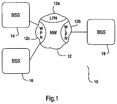
FIG. 1 depicts a block schematic diagram of a wireless LAN in accordance with the prior art;
FIG. 2 depicts a block schematic diagram of a first preferred embodiment of a wireless LAN in accordance with the present principles;
FIG. 3 depicts a time sequence of the events that occur within the network of FIG. 2 to control traffic to meet desired QoS levels; and
FIG. 4 depicts a block schematic diagram of a second preferred embodiment of a wireless LAN in accordance with the present principles.
Detailed description
FIG. 1 depicts a block schematic diagram of a wireless Local Area Network (LAN) 10 in accordance with the teachings of the prior art. The wireless LAN 10 includes at least one and preferably a plurality of Access Points (APs), exemplified by APs 12.sub.1 and 12.sub.2. Each AP, such as AP 12.sub.1, includes a radio transceiver for broadcasting radio frequency signals to, and for receiving radio frequency signals from one or more Mobile Terminal Users (MTUs), exemplified by MTU 14. Each AP thus serves as a gateway to enable the MTU 14 to down load traffic from, and to upload traffic to, a wired network 16 associated with the wireless LAN 10. The traffic exchanged between each MTU 14 and the wired network 16 can include voice as well as data, the later typically taking the form of Internet Protocol (IP) packets formatted in Ethernet frames.
An Inter-Working Gateway (IWG) 18 provides a communications path between the wired network 16 and an external network 20 which can include a private data network, a corporate intranet or a public data network such as the Internet, or a combination thereof. The IWG 18 not only interworks the wired network 16 and the external network 20, but also performs Authorization, Authentication and Accounting (AAA) functions. In other words, the IWG 18 serves to authorize the MTU 14 to obtain service, as well as to authenticate the MTU upon each access to the wireless LAN 10. Further, after authenticating the MTU 14, the IWG 18 accounts for the service rendered to the MTU for billing purposes.
The IWG 18 provides limited QoS level/service level management within the prior art Wireless LAN 10. At best, the IWG 18 can control each of APs 12.sub.1 and 12.sub.2 to provide the radio resources needed to achieve a prescribed QoS level/service level for traffic exchanged between each AP and associated MTU. However, the wired network 16 inside of the wireless LAN 10 typically uses the default Medium Access Protocol (MAC), which in turn, employs Carrier Sense Multiple Access (CSMA), which does not allow for QoS level management. At best, bandwidth is shared among all contenders and the service level is said to be best effort.
FIG. 2 depicts a wireless LAN 100 in accordance with a first preferred embodiment of the present principles. The LAN 100 includes at least one and preferably, a plurality of Access Points (APs), best exemplified by APs 120.sub.1, and 120.sub.2. Each AP provides radio access to one or more Mobile Terminal Users (MTUs), as exemplified by MTUs 140.sub.1, 140.sub.2, 140.sub.3, and 140.sub.4. In the illustrated embodiment, the AP 120.sub.1 provides radio access to the MTUs 120.sub.1-120.sub.3, whereas the AP 120.sub.2 provides radio access to the MTU 140.sub.4. However, each of the APs 120.sub.1 and 120.sub.2 has the capability of providing radio access to multiple MTUs in the same manner as each of the APs 12.sub.1 and 12.sub.2 of FIG. 2.
At the heart of the wireless LAN 100 is a wired network in the form of an Ethernet Switch 160 having Virtual Local Area Network (VLAN) capability, that is the ability to route each information frame in accordance with an identifier (i.e., a VLAN number) associated with the frame. The VLAN switch 160 controls the traffic flow between each of the APs 120.sub.1 and 120.sub.2 and one of a set of routing Inter-Working Gateways (IWGs), exemplified by IWGs 180.sub.1, 180.sub.2 and 180.sub.3, in accordance with a determined QoS level. As depicted in FIG. 3, each of the routing IWGs 180.sub.1-180.sub.3 has a connection to a corresponding one of the ports P1-P3, respectively, of the VLAN switch 160. Each of the APs 120.sub.1 and 120.sub.2 has a connection to each of ports P.sub.6 and P.sub.7, respectively.
In addition to the routing IWGs 80.sub.1-180.sub.3, the wireless LAN 100 of FIG. 2 includes an administrative IWG 180.sub.4 connected to port P4 of the VLAN switch 160. The IWG 180.sub.4 serves as a controller. In that regard, the IWG 180.sub.4 hosts an authentication proxy server (not shown) for performing the same Authorization, Authentication, and Administrative (AAA) functions as performed by the IWG 18 of FIG. 1. As part of the AAA functions it performs, the administrative IWG 180.sub.4 maintains a record for each MTU that designates an appropriate QoS level/service level for information frames received at an associated AP from each MTU. For example, the MTU 140.sub.1 could subscribe to a higher grade of service as compared to the MTU 140.sub.2. From such knowledge, the administrative IWG 180.sub.4 assigns an appropriate Virtual Local Area Network (VLAN) number for each frame that originates from each MTU. Normally, the VLAN number designates the identity of the network end-point destined to receive the frame in accordance with the IEEE 802.1Q standard. However, in accordance with present principles, the VLAN number used in the network to select the appropriate path (i.e., switch port) associated with a particular QoS level/service. The administrative IWG 180.sub.4 provides such VLAN number assignments to each AP. In the preferred embodiment, each of the APs 120.sub.1 and 120.sub.2 act Ethernet bridge devices for associating with each incoming frame an identification (i.e., the VLAN number) that designates the appropriate QoS level/service level accorded that frame.
Rather than rely on a static QoS level/service set during initiation of a communications session with the wireless LAN 100, each MTU could request a particular QoS level/service level for a new upcoming session on a dynamic basis. Stated another way, an MTU, such as MTU 140.sub.4, could send a request that one or more subsequently transmitted frames should be accorded a particular QoS level/service level. The AP 120.sub.2 forwards such a QoS level/service level request to the administrative IWG 180.sub.4, which in turn, instructs the AP to assign such frames a VLAN number that designates the requested QoS levevservice level.
The VLAN switch 160 in the wireless LAN 100 of FIG. 2 routes information frames from one of APs 120.sub.1 and 120.sub.2 to one of the routing IWGs 180.sub.1-180.sub.3 in accordance with the VLAN number assigned to each frame by each AP. The VLAN number associated with each frame enables the VLAN switch 160 to select the proper path for the received frame. As discussed in detail with respect to FIG. 3, when each MTU, such as MTU 140.sub.1 for example, initiates a communication session, that MTU not only receives an identifying IP address, but also receives an IP address for the routing IWGs 180.sub.1-180.sub.3. Although each of the routing IWGs 180.sub.1-180.sub.3 has the same IP address, each typically has a different QoS level/service level. Therefore, the VLAN switch 160 uses the VLAN number associated with each information frame received from an associated one of APs 120.sub.1, and 120.sub.2 to route the frame on an appropriate path (i.e., to route the frame to the appropriate one of the routing IWGs 180.sub.1-180.sub.3) to maintain the proper QoS level/service.
FIG. 3 illustrates a timing chart that depicts the sequence of events associated with QoS levevservice level control within the network 100 of FIG. 2. Initially, a MTU, such as MTU 140.sub.2 of FIG. 2, commences a communications session with the wireless LAN 100 by first establishing radio communication with an AP, such as AP 120.sub.1 of FIG. 2 during event 100 of FIG. 3. After establishing a communications session during step 100, the administrative IWG 180.sub.4 of FIG. 2 authenticates the MTU 140.sub.2 during event 120. As mentioned previously, during the course of authenticating the MTU 140.sub.2, the administrative IWG 180.sub.4 will assign an address (i.e., a source address) to the MTU for identification purposes in the wireless LAN 100 of FIG. 2. Further, the IWG 180.sub.4 will also provide to the MTU 140.sub.2 with the IP address (i.e., the destination address) of the routing IWGs 180.sub.1-180.sub.4. Additionally, in accordance with present principles, the administrative IWG 180.sub.4 will also determine appropriate QoS level/service for the frame in accordance with the identity of the originating MTU 140.sub.2 and communicate that information to the AP 120.sub.1. The AP 120.sub.1 will then assign to each incoming information frame a VLAN number that designates the QoS level/service level determined by the administrative IWG 180.sub.4 prior to routing the frame to the VLAN switch 160 for subsequent routing to the appropriate routing IWG, say IWG 1801 during event 140.
As mentioned previously, the originating MTU (i.e., MTU 140.sub.2 in FIG. 2) could request a particular QoS level/service/ level different from the static QoS level/service level set during initial commencement of the communications session. In response to such a request received through the AP 120.sub.1 in communication with the MTU 140.sub.2, the administrative IWG 180.sub.4 will instruct that AP to assign the appropriate VLAN number designating the requested QoS level/service level. In this way, the VLAN switch 160 will route the frames in accordance with the assigned VLAN number so that the frames are routed on the appropriate path to assure the proper QOS level/service level.
FIG. 4 depicts a block schematic diagram of an alternate preferred embodiment of a wireless LAN network 100' for controlling QoS levels in accordance with present principles. The wireless LAN network 100' of FIG. 4 shares many elements in common with the wireless LAN network 100 of FIG. 2 and therefore, like references have been used to identify like elements. The wireless LAN 100' of FIG. 4 differs from the wireless LAN 100 of FIG. 2 with respect to the number of routing IWGs. As described previously, the wireless LAN 100 of FIG. 2 includes three separate IWGs 180.sub.1-180.sub.3, each connected to a separate one of ports P1-P3, respectively of the VLAN switch 160. By comparison, the wireless LAN network 100' of FIG. 4 includes a single IWG router 180.sub.1' connected to each of the ports P1-P3 of the VLAN switch 160 via a separate one of interfaces 182.sub.1-182.sub.3, respectively.
The interfaces 182.sub.1-182.sub.3 typically each have different QoS level/service level parameters (e.g., for example different bandwidth). Upon receipt of an information frame from a particular AP, such as AP 120.sub.1 of FIG. 4, the VLAN switch 160 selects at least one of the interfaces 182.sub.1-182.sub.3 in accordance with the VLAN number assigned by that AP for routing the frame to the IWG 180.sub.1'. In this way, the VLAN switch 160 of FIG. 4 routes the frame on the appropriate path to meet the designated QoS level/service level.
The foregoing describes a technique for controlling Quality of Service (QoS) levels/services in a wired network associated with a wireless LAN by routing the traffic pursuant to an identifier associated traffic that designates the QoS level/service level.
 Lapsed, fee not paid10 drawings