Background
1. Technical field
The present invention relates to a projection type display system having a position detection function capable of projecting an image and optically detecting a position of a target object located within a detection area determined on the projection side of the image.
2. Related art
Recently, an electronic device such as a cellular phone, a car navigation system, a personal computer, a ticket machine, and a bank terminal unit includes a display system having a position detection function as a unit which has a touch panel on a front surface of an image producing device such as a liquid crystal device. According to this display system having the position detection function, information is inputted while referring to an image displayed on the image producing device. The touch panel is constituted by a position detection device for detecting a position of a target object within a detection area (for example, see JP-A-2001-142643, FIG. 6).
The position detection device disclosed in JP-A-2001-142643 is an optical type device which has a detection area on the image display surface side of a direct viewing type display system and includes a plurality of light emitting diodes and a plurality of photo-transistors on one side and the other side of the detection area, respectively. According to this position detection device, a position of a target object entering the detection area and blocking light can be detected by specifying the photo-transistor to which supply of the light is blocked by the target object.
The present inventor intends to propose a novel display system, i.e., a projection type display system having a position detection function which determines a detection area on the image projection side such as in the vicinity of a screen and detects a position of a target object located within the detection area. When the structure disclosed in JP-A-2001-142643 is applied to the novel projection type display system having the position detection function, a number of light emitting diodes and photo-transistors are required to be disposed around the detection area. This type of projection type display system having the position detection function is difficult to be put to practical use.
Summary
An advantage of some aspects of the invention is to provide a projection type display system having a position detection function capable of detecting a position of a target object without using a number of light emitting elements and light receiving elements around a detection area.
An aspect of the invention is directed to a projection type display system having a position detection function which projects an image from an image projection device and optically detects a position of a target object between a surface on which the image is projected and the image projection device including: a position detection light source unit disposed on the image projection device to emit position detection light toward the target object; a light detector which detects the position detection light reflected by the target object in a detection area; and a position detection unit which detects the position of the target object based on a light reception result obtained by the light detector. An intensity distribution of the position detection light is produced in an area to which the position detection light is supplied.
According to the projection type display system having the position detection function of this aspect of the invention, the position detection light source unit for emitting the position detection light toward the target object positioned between the surface on which the image is projected and the image projection device is provided, and the position detection light reflected by the target object in the detection area is detected by the light detector. Since the position detection light emitted from the position detection light source unit produces the intensity distribution in the detection area, the position detection unit can detect the position of the target object based on the light reception result obtained from the light detector by determining the relationship between the position and the intensity of the position detection light beforehand. Moreover, the position detection light source unit provided on the image projection device emits the position detection light from the image projection device. Thus, the necessity of providing a number of the light emitting elements around the detection area is eliminated.
In this aspect of the invention, it is preferable that the position detection light is infrared light. According to this structure, the position detection light does not become an obstacle to image display.
In this aspect of the invention, it is preferable that the intensity of the position detection light in the intensity distribution monotonously decreases or monotonously increases from one side to the other side in the area to which the position detection light is supplied. It is particularly preferable that the intensity of the position detection light in the intensity distribution linearly changes in the area to which the position detection light is supplied. According to this structure, the position of the target object can be accurately detected by a relatively simple process.
In this aspect of the invention, it is preferable that the position detection light source unit emits the position detection light from a front surface of the image projection device where a projection lens for projecting the image is disposed. That is, since the light for image display and the position detection light are emitted in the same direction, it is preferable that the light for image display and the position detection light are emitted from the front surface of the image projection device. According to this structure, the emission directions of the light for image display and the position detection light can be adjusted by controlling the direction of the front surface of the image projection device.
In this aspect of the invention, it is preferable that the position detection light source unit, the light detector, and the position detection unit are all disposed on the image projection device. According to this structure, the pixels necessary for the position detection are provided on the image projection device. Thus, the portability improves, and the optical axis direction of the light detector is adjustable by controlling the direction of the image projection device.
In this aspect of the invention, it is preferable that the light detector is disposed on the front surface of the image projection device. In this case, the light for image display and the position detection light are emitted in the same direction, and the light detector is disposed in this direction. Thus, in the structure which has the light detector on the front surface of the image projection device, the emission directions of the light for image display and the position detection light, and the direction of the optical axis center of the light detector can be adjusted only by controlling the direction of the front surface of the image projection device.
In this aspect of the invention, it is preferable that, when two directions crossing a projection direction of the image are X axis direction and Y axis direction, the position detection light source unit produces an intensity distribution for X coordinate detection in which an intensity changes in the X axis direction and an intensity distribution for Y coordinate detection in which an intensity changes in the Y axis direction as intensity distributions of the position detection light. According to this structure, the X-Y coordinates within the detection area can be detected.
In this aspect of the invention, it is preferable that the position detection light source unit produces a first intensity distribution for X coordinate detection in which a light amount decreases from the one side to the other side in the X axis direction and a second intensity distribution for X coordinate detection in which an intensity changes in the direction opposite to the direction of the first intensity distribution for X coordinate detection as the intensity distribution for X coordinate detection, and produces a first intensity distribution for Y coordinate detection in which a light amount decreases from the one side to the other side in the Y axis direction and a second intensity distribution for Y coordinate detection in which an intensity changes in the direction opposite to the direction of the first intensity distribution for Y coordinate detection as the intensity distribution for Y coordinate detection. According to this structure, the X coordinate can be accurately detected by using the first intensity distribution for X coordinate detection and the second intensity distribution for X coordinate detection. Also, the Y coordinate can be accurately detected by using the first intensity distribution for Y coordinate detection and the second intensity distribution for Y coordinate detection.
In this aspect of the invention, it is preferable that the position detection light source unit has a plurality of light emitting elements for emitting the position detection light, controls the balance of the emission light amount from the light emitting elements, and produces the intensity distribution of the position detection light. According to this structure, the intensity distribution of the position detection light can be formed in various directions only by using a relatively small number of the light emitting elements.
In this aspect of the invention, it is preferable that, when two directions crossing a projection direction of the image are X axis direction and Y axis direction, plural rows of the light emitting elements are disposed in both the X axis direction and the Y axis direction. According to this structure, the intensity distribution for X coordinate detection and the intensity distribution for Y coordinate detection can be easily produced.
In this aspect of the invention, the light emitting elements may be light emitting elements each of which has the wavelength peak in the same wavelength range.
In this aspect of the invention, it is preferable that the position detection light source unit has first light emitting elements for emitting first infrared light having the wavelength peak in a first wavelength range, and second light emitting elements for emitting second infrared light having the wavelength peak in a second wavelength range different from the first wavelength range as the plural light emitting elements. In this case, a first light detector having the sensitivity peak in the first wavelength range and a second light detector having the sensitivity peak in the second wavelength range are provided as the light detector. According to this structure, the intensity distributions in different directions are simultaneously produced by the first light emitting elements and the second light emitting elements, and the respective lights are received by the first light detector and the second light detector. Thus, the time required for the coordinate detection can be shortened.
Brief description of the drawings
The invention will be described with reference to the accompanying drawings, wherein like numbers reference like elements.
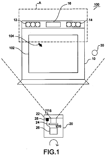
FIGS. 1A and 1B schematically illustrate the structure of a projection type display system having a position detection function according to a first embodiment of the invention.
FIGS. 2A and 2B illustrate an image projection device included in the projection type display system having the position detection function according to the first embodiment of the invention.
FIGS. 3A through 3C illustrate intensity distributions of position detection light used by the projection type display system having the position detection function according to the first embodiment of the invention and a process performed by a position detection unit.
FIGS. 4A and 4B illustrate signal processing performed by the projection type display system having the position detection function according to the first embodiment of the invention.
FIGS. 5A through 5D illustrate controls over light emitting elements of the projection type display system having the position detection function according to the first embodiment of the invention.
FIGS. 6A through 6D illustrate intensity distributions of position detection light produced by the projection type display system having the position detection function according to the first embodiment of the invention.
FIG. 7 schematically illustrates the main part of the structure of a projection type display system having a position detection function according to a fifth embodiment of the invention as diagonally viewed from above.
FIGS. 8A through 8C illustrate a first example of an error correction method performed by the projection type display system having the position detection function according to the embodiments of the invention.
FIGS. 9A through 9C illustrate a second example of an error correction method performed by the projection type display system having the position detection function according to the embodiments of the invention.
FIGS. 10A and 10B illustrate a third example of an error correction method performed by the projection type display system having the position detection function according to the embodiments of the invention.
Description of exemplary embodiments
Exemplary embodiments according to the invention are hereinafter described in detail with reference to the appended drawings. In the following explanation, X axis, Y axis, and Z axis crossing each other are used, and an image is projected in a direction along the Z axis direction. In the respective figures referred to in the embodiments, the X axis direction corresponds to the horizontal direction, and the Y axis direction corresponds to the vertical direction. In addition, in the respective figures referred to in the embodiments, the X axis direction has X1 side and X2 side as one side and the other side, respectively, and the Y axis direction has Y1 side and Y2 side as one side and the other side, respectively.
First Embodiment
General Structure of Projection Type Display System Having Position Detection Function
FIGS. 1A and 1B schematically illustrate the structure of a projection type display system having a position detection function according to a first embodiment, wherein: FIG. 1A schematically shows the main part of the projection type display system having the position detection function as diagonally viewed from above; and FIG. 1B schematically shows the main part of the projection type display system having the position detection function as viewed in the horizontal direction. FIGS. 2A and 2B illustrate an image projection device included in the projection type display system having the position detection function according to the first embodiment of the invention, wherein: FIG. 2A shows the image projection device as viewed from the front surface; and FIG. 2B shows the electric structure and the like of the projection type display system having the position detection function.
A projection type display system having a position detection function 100 shown in FIGS. 1A and 1B and FIGS. 2A and 2B includes an image projection device 200 called a liquid crystal projector or a digital micromirror device. This image projection device 200 projects enlarged image display light L1 from a projection lens 210 (see FIG. 2A) provided on a front surface 201 of a housing 250 toward a screen 290. Thus, the image projection device 200 has an optical device 260 provided within the housing 250 to produce color image display light and emit the color image light through the projection lens 210. In this embodiment, the screen 290 has a quadrangular shape elongated in the horizontal direction.
As will be described later, the projection type display system having the position detection function 100 in this embodiment has a function of optically detecting a position of a target object Ob within a detection area 10R determined before the screen 290 as the image projection side.
For providing this position detection function, the projection type display system having the position detection function 100 in this embodiment has a position detection light source unit 11 which emits position detection light L2 constituted by infrared light toward the detection area 10R to produce an intensity distribution of the position detection light L2 in the detection area 10R. The projection type display system having the position detection function 100 further includes a light detector 30 for detecting position detection light L3 reflected by the target object Ob in the detection area 10R, and a position detection unit 50 for detecting the position of the target object Ob based on the light reception result obtained from the light detector 30.
As illustrated in FIGS. 2A and 2B, the position detection light source unit 11 of the projection type display system having the position detection function 100 in this embodiment has a plurality of light emitting elements 12, and a light source drive unit 14 for driving the plural light emitting elements 12. In this embodiment, the position detection light source unit 11 (the light emitting elements 12 and the light source drive unit 14) is provided on the image projection device 200. More specifically, the projection lens 210 is disposed on the front surface 201 of the image projection device 200 substantially at the center in the X direction, and the plural light emitting elements 12 are disposed on the front surface 201 on both sides of the projection lens 210 in the X axis direction.
The plural light emitting elements 12 are divided into a first light emitting element group 121, a second light emitting element group 122, a third light emitting element group 123, and a fourth light emitting element group 124 in four positions of the front surface 201 of the image projection device 200. Each of the first light emitting group 121, the second light emitting group 122, the third light emitting element group 123, and the fourth light emitting element group 124 has the plural light emitting elements 12 in both the X axis direction and the Y axis direction. In this embodiment, each of the first light emitting group 121, the second light emitting group 122, the third light emitting element group 123, and the fourth light emitting element group 124 has six rows in the X axis direction and three rows in the Y axis direction.
The first light emitting element group 121 and the second light emitting element group 122 positioned on the one side X1 in the X axis direction with respect to the projection lens 210 are provided on a common substrate as a first light emitting element array 12a. The third light emitting element group 123 and the fourth light emitting element group 124 positioned on the other side X2 in the X axis direction with respect to the projection lens 210 are provided on a common substrate as a second light emitting element array 12b.
In this embodiment, the light emitting elements 12 are LEDs (light emitting diodes) or the like capable of emitting position detection light constituted by infrared light as divergence light. It is preferable that the position detection light has a wavelength range allowing efficient reflection by the target object Ob such as a finger and a touch pen. Thus, when the target object Ob is a human body such as a finger, it is preferable that the position detection light is infrared light having high reflectance on the surface of the human body (particularly near infrared light close to the visible light range such as light having a wavelength around 850 nm) or infrared light having 950 nm. In this embodiment, each of the light emitting elements 12 emits infrared light having the peak wavelength in the wavelength range around 850 nm. In some applications, an optical member such as a scattering plate and a prism sheet is provided on each of the light exit surfaces sides of the first light emitting element array 12a and the second light emitting element array 12b.
The light source drive unit 14 has a light source drive circuit 140 for driving the light emitting elements 12, and a light source controller 145 for controlling respective light emission intensities of the plural light emitting elements 12 via the light source drive circuit 140. The light source drive circuit 140 has a first light source drive circuit 141 for driving the light emitting elements 12 included in the first light emitting element array 12a, and a second light source drive circuit 142 for driving the light emitting elements 12 included in the second light emitting element array 12b. The light source controller 145 controls both the first light source drive circuit 141 and the second light source drive circuit 142.
In this embodiment, the light detector 30 and the position detection unit 50 are disposed on the image projection device 200 similarly to the position detection light source unit 11. The position detection unit 50 is positioned inside the image projection device 200.
The light detector 30 has a first light detector 31 and a second light detector 32 as two components disposed on the front surface 201 of the image projection device 200 on one side and the other side of the projection lens 210 in the Y axis direction, respectively. The light detector 30 (the first light detector 31 and the second light detector 32) is constituted by photo-diodes or photo-transistors, for example. In this embodiment, the light detector 30 is constituted by photo-diodes. The first light detector 31 and the second light detector 32 are electrically connected with the position detection unit 50, and the detection results from the first light detector 31 and the second light detector 32 are outputted to the position detection unit 50. In this embodiment, the anode and the cathode of the first light detector 31 are electrically connected with the anode and the cathode of the second light detector 32, respectively, allowing the first light detector 31 and the second light detector 32 to be electrically connected in parallel.
Basic Theory of Coordinate Detection
According to the projection type display system having the position detection function 100 in this embodiment, the position detection light source unit 11 turns on the light emitting elements 12 and forms the intensity distribution of the position detection light L2 in the detection area 10R, and the position detection unit 50 detects the position of the target object Ob within the detection area 10R based on the detection result of the position detection light L2 reflected by the target object Ob and detected by the light detector 30 (the first light detector 31 and the second light detector 32). The structure of light intensity distribution and the theory of coordinate detection are now explained with reference to FIGS. 3A through 3C.
FIGS. 3A through 3C show intensity distributions of the position detection light used by the projection type display system having the position detection function 100 and a process performed by the position detection unit 50 according to the first embodiment, wherein: FIG. 3A shows an intensity distribution of the position detection light in the X axis direction; FIG. 3B shows intensities of the position detection light reflected by the target object; and FIG. 3C shows the control of the intensity distributions of the position detection light such that the intensities of the position detection light reflected by the target object can be uniform.
According to the projection type display system having the position detection function 100 in this embodiment, the intensity distribution of the position detection light L2 is produced in the detection area 10R based on the distance from the position detection light source unit 11 and the lighting pattern of the light emitting elements 12 when the position detection light L2 is emitted from the position detection light source unit 11. For detecting an X coordinate, for example, a first intensity distribution for X coordinate detection L2Xa where intensity monotonously decreases from the one side X1 to the other side X2 in the X axis direction is produced in a first term, and then a second intensity distribution for X coordinate detection L2Xb where intensity monotonously decreases from the other side X2 to the one side X1 in the X axis direction is produced in a second term as illustrated in FIGS. 3A and 3B. More preferably, the first intensity distribution for X coordinate detection L2Xa where intensity linearly decreases from the one side X1 to the other side X2 in the X axis direction is produced in the first term, and then the second intensity distribution for X coordinate detection L2Xb where intensity linearly decreases from the one other side X2 to the one side X1 in the X axis direction is produced in the second term. When the target object Ob is disposed in the detection area 10R, the position detection light L2 is reflected by the target object Ob. Then, a part of the reflection light is detected by the light detector 30. Thus, when the first intensity distribution for X coordinate detection L2Xa in the first term and the second intensity distribution L2Xb for X coordinate detection in the second term are provided as distributions established in advance, the X coordinate of the target object Ob can be detected by the following methods, for example, based on the detection result from the light detector 30.
For example, a first method uses the difference between the first intensity distribution for X coordinate detection L2Xa and the second intensity distribution for X coordinate detection L2Xb shown in FIG. 3B. Since the first intensity distribution for X coordinate detection L2Xa and the second intensity distribution for X coordinate detection L2Xb are distributions established in advance, the difference between the first intensity distribution for X coordinate detection L2Xa and the second intensity distribution for X coordinate detection L2Xb becomes a function determined beforehand. Thus, the X coordinate of the target object Ob can be detected by calculating the difference between a detection value Lxa obtained from the light detector 30 at the time when the first intensity distribution for X coordinate detection L2Xa in the first term is produced and a detection value LXb obtained from the light detector 30 at the time when the second intensity distribution for X coordinate detection L2Xb in the second term is produced. According to this method, even when environmental light other than the position detection light L2 such as infrared component contained in the external light enters the light detector 30, the intensity of the infrared component included in the environmental light is canceled at the time of calculation of the difference between the detection values LXa and LXb. Thus, the infrared component included in the environmental light does not affect the detection accuracy.
A second method detects the X coordinate of the target object Ob based on the adjustment of the control amount (drive current) over the light emitting elements 12 for controlling the detection value LXa obtained from the light detector 30 at the time when the first intensity distribution for X coordinate detection L2Xa in the first term is produced and the detection value LXb obtained from the light detector 30 at the time when the second intensity distribution for X coordinate detection L2Xb in the second term is produced such that these values LXa and LXb become equal. This method can be employed when the X coordinates of the first intensity distribution for X coordinate detection L2Xa and the second intensity distribution for X coordinate detection L2Xb shown in FIG. 3B linearly change.
Initially, the first intensity distribution for X coordinate detection L2Xa in the first term and the second intensity distribution for X coordinate detection L2Xb in the second term are so established as to have the same absolute values and reversely change in the X axis direction as illustrated in FIG. 3B. In this condition, when the detection value LXa obtained from the light detector 30 in the first term is equal to the detection value LXb obtained from the light detector 30 in the second term, it is determined that the target object Ob lies at the center in the X axis direction.
When the detection value LXa obtained from the light detector 30 in the first term is different from the detection value LXb obtained from the light detector 30 in the second term, the control amount (drive current) over the light emitting elements 12 is controlled such that the detection values LXa and LXb can be equalized. Then, the first intensity distribution for X coordinate detection L2Xa in the first term and the second intensity distribution for X coordinate detection L2Xb in the second term are again produced as illustrated in FIG. 3C. As a result, the detection value LXa from the light detector 30 in the first term and the detection value LXb from the light detector 30 in the second term become equal to each other, and thus the X coordinate of the target object Ob can be detected based on the ratio or difference between an adjustment amount .DELTA.LXa for the adjustment of the control amount over the light emitting elements 12 in the first term and an adjustment amount .DELTA.LXb for the adjustment of the control amount over the light emitting elements 12 in the second term, for example. According to this method, even when environmental light other than the position detection light L2 such as infrared component contained in the external light enters the light detector 30, the intensity of the infrared component included in the environmental light is canceled at the time of adjustment for the control amount over the light emitting elements 12 such that the detection values LXa and LXb can be equalized. Thus, the infrared component included in the environmental light does not affect the detection accuracy.
A third method detects the X coordinate of the target object Ob based on the adjustment of the control amount (drive current) over the light emitting elements 12 for controlling the detection value LXa obtained from the light detector 30 at the time when the first intensity distribution for X coordinate detection L2Xa in the first term is produced and the detection value LXb obtained from the light detector 30 at the time when the second intensity distribution for X coordinate detection L2Xb in the second term is produced such that these values LXa and LXb can be equalized similarly to the second method. This method can be employed when the X coordinates of the first intensity distribution for X coordinate detection L2Xa and the second intensity distribution for X coordinate detection L2Xb shown in FIG. 3B linearly change.
Initially, the first intensity distribution for X coordinate detection L2Xa in the first term and the second intensity distribution for X coordinate detection L2Xb in the second term are so established as to have the same absolute values and reversely change in the X axis direction as illustrated in FIG. 3B. In this condition, when the detection value LXa obtained from the light detector 30 in the first term is equal to the detection value LXb obtained from the light detector 30 in the second term, it is determined that the target object Ob lies at the center in the X axis direction.
When the detection value LXa from the light detector 30 in the first term is different from the detection value LXb from the light detector 30 in the second term, the control amount (drive current) over the light emitting elements 12 in the term corresponding to the lower detection value or in the term corresponding to the higher detection value is controlled, for example, such that the detection values LXa and LXb can be equalized. Then, the first intensity distribution for X coordinate detection L2Xa in the first term and the second intensity distribution for X coordinate detection L2Xb in the second term are again produced. According to the example shown in FIG. 3B, the control amount over the light emitting elements 12 in the first term is decreased by the adjustment amount .DELTA.LXa, or the control amount over the light emitting elements 12 in the second term is increased by the adjustment amount .DELTA.LXb, for example. As a result, the detection value LXa from the light detector 30 in the first term and the detection value LXb from the light detector 30 in the second term become equal to each other, and thus the X coordinate of the target object Ob can be detected based on the ratio or difference between the control amount over the light emitting elements 12 in the first term after adjustment of the control amount and the control amount over the light emitting elements 12 in the second term after adjustment of the control amount, for example. According to this method, even when environmental light other than the position detection light L2 such as infrared component contained in the external light enters the light detector 30, the intensity of the infrared component included in the environmental light is canceled at the time of adjustment for the control amount over the light emitting elements 12 such that the detection values LXa and LXb can be equalized. Thus, the infrared component included in the environmental light does not affect the detection accuracy.
In each of the first through third methods, a first intensity distribution for Y coordinate detection where the intensity monotonously decreases from the one side Y1 to the other side Y2 in the Y axis direction is produced in a third term, and then a second intensity distribution for Y coordinate detection where the intensity monotonously decreases from the other side Y2 to the one side Y1 in the Y axis direction is produced in a fourth term, based on the intensity distributions for Y coordinate detection the Y coordinate of the target object Ob can be detected. Also, an intensity distribution in the Z axis direction is produced in a fifth term, based on the intensity distribution the Z coordinate of the target object Ob can be detected.
According to this structure, the information on the position of the target object Ob within the detection area 10R based on the detection result from the light detector 30 can be obtained by executing predetermined software (operation program) using a microprocessor unit (MPU) as the position detection unit 50 for performing associated processes, for example. Alternatively, as described herein with reference to FIGS. 4A and 4B, the processes may be performed by a signal processing unit using hardware such as a logic circuit.
Structure Example of Position Detection Unit 50
FIGS. 4A and 4B illustrate signal processing performed by the projection type display system having the position detection function 100 according to the first embodiment of the invention, wherein: FIG. 4A shows the position detection unit 50 of the projection type display system having the position detection function 100 as an example of the invention; and FIG. 4B shows a process performed by a light emission intensity compensation command section of the position detection unit 50. The position detection unit 50 explained herein carries out the method which detects the X coordinate of the target object Ob based on the adjustment of the control amount (drive current) over the light emitting elements 12 for controlling the detection values LXa and LXb obtained from the light detector 30 in the first term and the second term such that these values LXa and LXb can be equalized. Since the same structure is used for detecting the X coordinates and the Y coordinates, only the case for obtaining the X coordinates is herein discussed.
As illustrated in FIG. 4A, according to the projection type display system having the position detection function 100 in this embodiment, the light source drive circuit 140 applies a drive pulse of predetermined current to each of the plural light emitting elements 12 via a variable resistor 111 in the first term, and applies a drive pulse of predetermined current to each of the plural light emitting elements 12 via a variable resistor 112 and a reverse circuit 113 in the second term. Thus, the light source drive circuit 140 applies drive pulses in opposite phases to the light emitting elements 12 in the first term and the second term. Then, the position detection light L2 at the time when the first intensity distribution for X coordinate detection L2Xa in the first term is produced is reflected by the target object Ob and received by the common light detector 30, and the position detection light L2 at the time when the second intensity distribution for X coordinate detection L2Xb in the second term is produced is reflected by the target object Ob and received by the common light detector 30. In the section of a light intensity signal producing circuit 150, a resistor 30r having approximately 1 k.OMEGA. is electrically connected with the light detector 30 in series, and bias voltage Vb is applied to both ends of the connected light detector 30 and resistor 30r.
In the light intensity signal producing circuit 150, the position detection unit 50 is electrically connected with a connection point P1 between the light detector 30 and the resistor 30r. A detection signal Vc outputted from the connection point P1 between the light detector 30 and the resistor 30r is expressed by the following equation. Vc=V30/(V30+resistance value of resistor 30r) V30: equivalent resistance of light detector 30 Thus, comparing the case in which the environmental light does not enter the light detector 30 with the case in which the environmental light enters the light detector 30, the level and the amplitude of the detection signal Vc become higher when the environmental light enters the light detector 30.
The position detection unit 50 chiefly includes a position detection signal extracting circuit 190, a position detection signal separating circuit 170, and a light emission intensity compensation command circuit 180.
The position detection signal extracting circuit 190 has a filter 192 constituted by a capacitor of approximately 1 nF. The filter 192 functions as a high-pass filter which removes a direct current component from a signal outputted from the connection point P1 between the light detector 30 and the resistor 30r. Thus, the filter 192 extracts a position detection signal Vd of the position detection light L2 produced by the light detector 30 in each of the first term and the second term from the detection signal Vc outputted from the connection point P1 between the light detector 30 and the resistor 30r. In other words, the filter 192 removes a low frequency component or a direct current component contained in the environmental light based on the determination that the intensity of the environmental light is constant in a certain period unlike the modulated position detection light L2.
The position detection signal extracting circuit 190 has an addition circuit 193 including a feedback resistor 194 of approximately 220 k.OMEGA. and disposed after the filter 192. The position detection signal Vd extracted by the filter 192 is outputted to the position detection signal separating circuit 170 as a position detection signal Vs superimposed on voltage V/2 as the bias voltage Vb multiplied by 1/2.
The description continues in the full USPTO document.
 Lapsed, fee not paid23 drawings