 Lapsed, fee not paid17 drawings
Software & Apps · US 8,745,528 B2
Utility object for specialized data entry
An object is associated with one or more controls in a software application.
US 8,745,535 B2 · Assignee: Apple Inc. · Inventors: Chaudhri; Imran A. et al.
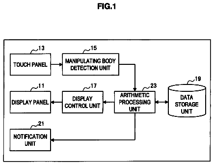
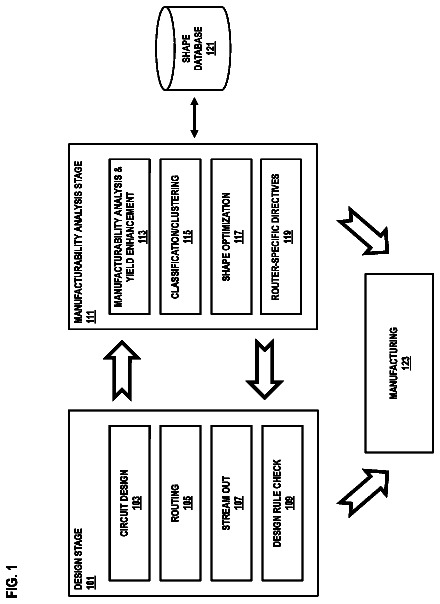
Sheet 1 of 31 from the published document. All sheets in the USPTO PDF
A graphical user interface has a back surface disposed from viewing surface to define a depth, and one or more one or more side surfaces extend from the back surface to the viewing surface. An icon receptacle is disposed on one or more of the side surfaces, and one or more icons are disposed within the icon receptacle. The one or more icons correspond to one or more desktop items.
A graphical user interface allows a large number of graphical objects or items to be displayed on a display screen at the same time. Leading personal computer operating systems, such as the Apple Mac OS.RTM., provide user interfaces in which a number of visualizations of system objects can be displayed according to the needs of the user. Example system objects include system functions, alerts, windows, peripherals, files, and applications. Taskbars, menus, virtual buttons, a mouse, a keyboard, and other user interface elements provide mechanisms for accessing and/or activating the system objects corresponding to the displayed representations. The graphical objects and access to the corresponding system objects and related functions, however, should be presented in a manner that facilitates an intuitive user experience. The use of metaphors that represent concrete, familiar ideas facilita
1 of 31 drawing sheets so far from the published document, cropped to the drawing. Every sheet is in the USPTO PDF.
What the patent claimed, word for word. All of it is now free to use.
A graphical user interface allows a large number of graphical objects or items to be displayed on a display screen at the same time. Leading personal computer operating systems, such as the Apple Mac OS.RTM., provide user interfaces in which a number of visualizations of system objects can be displayed according to the needs of the user. Example system objects include system functions, alerts, windows, peripherals, files, and applications. Taskbars, menus, virtual buttons, a mouse, a keyboard, and other user interface elements provide mechanisms for accessing and/or activating the system objects corresponding to the displayed representations.
The graphical objects and access to the corresponding system objects and related functions, however, should be presented in a manner that facilitates an intuitive user experience. The use of metaphors that represent concrete, familiar ideas facilitate such an intuitive user experience. For example, the metaphor of file folders can be used for storing documents; the metaphor of a file cabinet can be used for storing information on a hard disk; and the metaphor of the desktop can be used for an operating system interface.
As the capabilities of processing devices progress, however, so do the demands on the graphical user interface to convey information to the users in an intuitive manner.
Disclosed herein are systems, apparatus and methods, including a multidimensional desktop graphical user interface. In one implementation, a graphical user interface includes a back surface that is axially disposed from a viewing surface, and one or more side surfaces that are extended from the back surface to the viewing surface. A visualization object receptacle, e.g., icon receptacle, is displayed on one or more of the side surfaces, and one or more visualization objects, e.g., icons corresponding to one or more system objects can be displayed within the icon receptacle.
In another implementation, a two-dimensional, desktop can be depth-transitioned from a viewing surface to a back surface, and one or more side surfaces can be extended from the back surface to the viewing surface. A visualization object receptacle, e.g., icon receptacle on the one or more side surfaces can be generated. One or more visualization objects, e.g., icons corresponding to the desktop items can likewise be generated within the icon receptacle.
In another implementation, a graphical user interface includes a viewing surface and a back surface axially disposed from the viewing surface to define a depth. One or more side surfaces can extend from the back surface to the viewing surface, and a visualization object receptacle can be disposed on one or more of the side surfaces. One or more visualization objects corresponding to the desktop items can likewise be disposed within the icon receptacle.
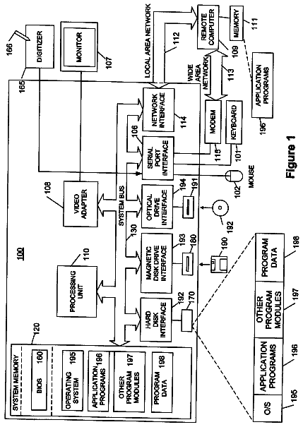
FIG. 1 is a block diagram of an example system that can be utilized to implement the systems and methods described herein.
FIG. 2 is a block diagram of an example user interface architecture.
FIG. 3 is an image of an example visualization object receptacle.
FIG. 4 is an image of an example stack item.
FIG. 5 is a block diagram of an example user interface engine architecture.
FIG. 6 is a block diagram of an example system layer structure that can be utilized to implement the systems and methods described herein.
FIG. 7 is a block diagram of an example multidimensional desktop environment.
FIG. 8 is another block diagram of the example multidimensional desktop environment.
FIG. 9 is another block diagram of the example multidimensional desktop environment.
FIG. 10 is another block diagram of the example multidimensional desktop environment.
FIG. 11 is a block diagram of another example multidimensional desktop environment.
FIG. 12 is a block; diagram of another example multidimensional desktop environment.
FIG. 13 is a block diagram of another example multidimensional desktop environment.
FIG. 14 is a block diagram of another example multidimensional desktop environment.
FIG. 15 is a block diagram of another example multidimensional desktop environment.
FIGS. 16A-D are block diagrams of other example multidimensional desktop environments.
FIG. 17 is a block diagram of an example desktop transition.
FIGS. 18A-18D are block diagrams of example visualization object receptacle indicators.
FIGS. 19A and 19B are block diagrams of an example contextual menu for a visualization object receptacle.
FIG. 20 is a block diagram of an example visualization object receptacle including type-ahead indications.
FIGS. 21A and 21B are block diagrams of example selection indicators for a visualization model.
FIG. 22 is a block diagram of another example multidimensional desktop environment.
FIG. 23 is a block diagram of another example visualization object receptacle.
FIG. 24 is a block diagram of an example stack item.
FIG. 25 is a block diagram of another example stack item.
FIG. 26 is a block diagram of another example stack item.
FIG. 27 is a block diagram of another example stack item.
FIGS. 28A and 28B are block diagrams of example stack items that are color-coded.
FIG. 29 is a block diagram illustrating an example contextual control scheme applied to an example stack item.
FIG. 30 is a block diagram illustrating the application of an example visualization model to an example stack item.
FIGS. 31A and 31B are block diagrams illustrating the application of another example visualization model to an example stack item.
FIG. 32 is a block diagram illustrating the application of another example visualization model to an example stack item.
FIG. 33A is a block diagram of an example group association of an example stack item.
FIG. 33B is a block diagram of an example group association of system objects.
FIG. 34 is a flow diagram of an example process for transitioning a desktop.
FIG. 35 is a flow diagram of another example process for transitioning between desktop types.
FIG. 36 is a flow diagram of an example process for generating a multidimensional desktop environment.
FIG. 37 is a flow diagram of an example process for rendering a side surface in a multidimensional desktop environment.
FIG. 38 is a flow diagram of an example process for scrolling a side surface in a multidimensional desktop environment.
FIG. 39 is a flow diagram of an example process for generating a selection indicator.
FIG. 40 is a flow diagram of an example process for rendering desktop items.
FIG. 41 is a flow diagram of an example process for generating an example application environment in a multidimensional desktop environment.
FIG. 42 is a flow diagram of an example process for transitioning between application environments.
FIG. 43 is a flow diagram of an example process for generating a visualization object receptacle.
FIG. 44 is a flow diagram of an example process for color coding visualization objects.
FIG. 45 is a flow diagram of an example process for color coding visualization objects of related system objects.
FIG. 46 is a flow diagram of another example process for generating a visualization object receptacle.
FIG. 47 is a flow diagram of an example process for generating a stack item.
FIG. 48 is a flow diagram of an example process for displaying stack elements according to modal states.
FIG. 49 is a flow diagram of an example process for selecting interaction models and/or visualization models.
FIG. 50 is allow diagram of another example process for generating a stack item.
FIG. 51 is a flow diagram of an example process for displaying a stack item according to an execution context.
FIG. 52 is a flow diagram of an example process for generating and displaying a stack item.
FIG. 53 is a flow diagram of an example process for automatically selecting and applying an interaction model to a stack item.
FIG. 54 is a flow diagram of another example process for automatically selecting and applying an interaction model to a stack item.
FIG. 55 is a flow diagram of another example process for automatically selecting and applying an interaction model to a stack item.
FIG. 56 is a flow diagram of another example process for automatically selecting and applying an interaction model to a stack item.
FIG. 57 is a flow diagram of an example process for generating a divet.
FIG. 58 is a flow diagram of an example process for generating a divet contextual menu.
FIG. 1 is a block diagram of an example system 100 that can be utilized to implement the systems and methods described herein. The system 100 can, for example, be implemented in a computer device, such as any one of the personal computer devices available from Apple Inc., or other electronic devices. Other example implementations can also include video processing devices, multimedia processing devices, portable computing devices, portable communication devices, set top boxes, and other electronic devices.
The example system 100 includes a processing device 102, a first data store 104, a second data store 106, a graphics device 108, input devices 110, output devices 112, and a network device 114. A bus system 116, such as a data bus and a motherboard, can be used to establish and control data communication between the components 102, 104, 106, 108, 110, 112 and 114. Other example system architectures, however, can also be used.
The processing device 102 can, for example, include one or more microprocessors. The first data store 104 can, for example, include a random access memory storage device, such as a dynamic random access memory, or other types of computer-readable medium memory devices. The second data store 106 can, for example, include one or more hard drives, a flash memory, and/or a read only memory, or other types of computer-readable medium memory devices.
The graphics device 108 can, for example, include a video card, a graphics accelerator card, or a display adapter, and is configured to generate and output images to a display device. In one implementation, the graphics device 108 can be realized in a dedicated hardware card connected to the bus system 116. In another implementation, the graphics device 108 can be realized in a graphics controller integrated into a chipset of the bus system 116. Other implementations can also be used.
Example input devices 110 can include a keyboard, a mouse, a stylus, a video camera, a multi-touch surface, etc., and example output devices 112 can include a display device, an audio device, etc.
The network interface 114 can, for example, include a wired or wireless network device operable to communicate data to and from a network 118. The network 118 can include one or more local area networks (LANs) or a wide area network (WAN), such as the Internet.
In an implementation, the system 100 includes instructions defining an operating system stored in the first data store 104 and/or the second data store 106. Example operating systems can include the MAC OS.RTM. X series operating system, the WINDOWS.RTM. based operating system, or other operating systems. Upon execution of the operating system instructions, access to various system objects is enabled. Example system objects include data files, applications, functions, windows, etc. To facilitate an intuitive user experience, the system 100 includes a graphical user interface that provides the user access to the various system objects and conveys information about the system 100 to the user in an intuitive manner.
FIG. 2 is a block diagram of an example user interface architecture 200. The user interface architecture 200 includes a user interface (UI) engine 202 that provides the user access to the various system objects 204 and conveys information about the system 100 to the user.
Upon execution, the UI engine 202 can cause the graphics device 108 to generate a graphical user interlace on an output device 112, such as a display device. In one implementation, the graphical user interface can include a multidimensional desktop 210 and a multidimensional application environment 212. In an implementation, the multidimensional desktop 210 and the multidimensional application environment 212 include x-, y- and z-axis aspects, e.g., a height, width and depth aspect. The x-, y- and z-axis aspects may define a three-dimensional environment, e.g., a "3D" or "2.5D" environment that includes a z-axis, e.g., depth, aspect.
In an implementation, the multidimensional desktop 210 can include use interface elements, such as visualization objects 220, a visualization object receptacle 222, and stack items 224. In some implementations, the visualization objects 220, the visualization object receptacle 222 and the stack items 224 can be presented in a pseudo-three dimensional (i.e., "2.5D") or a three-dimensional environment as graphical objects having a depth aspect.
A visualization object 220 can, for example, be a visual representation of a system object. In some implementations, the visualization objects 220 are icons. Other visualization objects can also be used, e.g., alert notification windows, menu command bars, windows, or other visual representations of system objects.
In an implementation, the multidimensional application environment 212 can include an application environment distributed along a depth aspect. For example, a content frame, e.g., an application window, can be presented on a first surface, and control elements, e.g., toolbar commands, can be presented on a second surface.
FIG. 3 is an image of an example visualization object receptacle 300. In one implementation, the visualization object receptacle 300 can include x-, y- and z-axis aspects, e.g., a height, width and depth. In another implementation, the visualization object receptacle 300 can have only a y- and z-axis aspect, e.g., a width and depth. In another implementation, the visualization object receptacle 300 can have only an x- and y-axis aspect, e.g., a height and a width. An example, implementation of a visualization object receptacle 300 is the "Dock" user interface in the MAC OS.RTM. X Leopard operating system. Other implementations can also be used.
In some implementations, or more visualization, objects, e.g., icons 304, 306, 308 and 310 can be disposed within the visualization object receptacle 300, e.g., an icon receptacle 300. In one implementation, a lighting arid shading effect is applied to emphasize the depth aspect of the visualization object receptacle 300, as illustrated by the corresponding shadows 305, 307, 309 and 311 and reflections 312, 314, 316 and 318 beneath each of the icons 304, 306, 308 and 310.
In some implementations, the visualization object receptacle 300 can include front surface 319 to generate a height aspect. In some implementations, a notch 320 can be included in the visualization object receptacle 300. The notch 320 can, for example, be utilized to arrange visualization objects related to particular programs or functions, e.g., files and folders can be disposed on a first side of the notch 320 and applications can be disposed on a second side of the notch 320; or a user may define arrangements according to the notch 320, etc.
In some implementations, the visualization object receptacle 300 can include status indicators, e.g., 330 and 332, disposed on the front surface 319. The status indicators 330 and 332 can, for example, appear as illuminations to indicate a status of a system object or function associated with a corresponding visualization object. In some implementations, the status indicators can be color coded based on an identified status. For example, the status indicator 330 may be illuminate in a yellow color to indicate that the folder 304 is receiving a file download, and the status indicator 332 may be illuminate in a green color to indicate that a program associated with the visualization object 308 is running.
In some implementations, the visualization object receptacle 300 may only define a depth aspect, e.g., the visualization object receptacle 300 may not include a front surface 319. In some implementations, the top surface of the visualization object receptacle 300 can be modeled as a liquid for addition and removal of visualization objects. For example, when a visualization object is added to the visualization object receptacle 300, the adjacent visualization objects may move apart to define an open space, and the added visualization object may emerge from the surface into the open space. Surface perturbations, e.g., ripples, can be generated to enhance the visual effect of the addition of the visualization object. Visualization objects can be removed by a substantially reversed visual effect.
In another implementation, when a visualization object is added to the visualization object receptacle 300, the adjacent visualization objects may move apart to define an open space, and the added visualization object may fall onto the surface into the open space. Surface perturbations, e.g., ripples and splashes, can be generated to enhance the visual effect of the addition of the visualization object. Visualization objects can be removed by a substantially reversed visual effect. Additional features of visualization object receptacles and visualization objects disposed therein are described in more detail below.
FIG. 4 is an image of an example stack item 400. In one implementation, the stack item 400 is a system object that includes a plurality of stack elements, e.g., stack elements 402, 404, 406 and 408, such as icons corresponding to system objects, or other visualizations of system objects. The stack item 400 is associated with the stack elements 402, 404, 406 and 408 so that selection of the stack item can provide access to any of the stack elements 402, 404, 406 and 408. In one implementation, a stack element can, for example, be realized by a corresponding visualization object of a system object. In another implementation, a stack element can, for example, be realized, by a corresponding thumbnail icon of a system object. In another implementation, a stack element can, for example, be realized by a different corresponding icon of a system object. In another implementation, a stack element can, for example, be realized by a common stack element icon. Other stack element realizations with icons and/or other visualization objects can also be used.
In one implementation, a stack item identifier 410 can be displayed on the top stack element, e.g., stack element 402. In one implementation, the stack item identifier 410 can, for example, comprise a title describing a stack type, e.g., "images" or "documents." In another implementation, the stack item identifier 410 can, for example, comprise a visual indicator indicating an aspect of the stack, e.g., a dollar sign $ can be displayed for a stack item including system objects related to a financial analysis tool; or a representation of a coin can be displayed as a surface beneath the stack item, etc. The stack item identifier 410 can, for example, be automatically generated, or can be generated by the user. Other stack item identifiers can also be used.
In one implementation, the stack elements 402, 404, 406 and 408 are aggregated in an overlapping arrangement as shown in FIG. 4. Other stack arrangements can also be used. In one implementation, each stack element 402, 404, 406 and 408 displays a corresponding unique indicium 412, 414, 416 and 418, e.g., a thumbnail preview of an image associated with the stack element or the first page of a document associated with the stack element. Other unique indicium or unique indicia can also be used. For example, stack elements corresponding to images can be of the same aspect of the image, e.g., a 4.times.5 aspect, and 9.times.12 aspect, etc. Likewise, stack items corresponding to documents can be of the same aspect of a paper selection, e.g., an 8.5.times.11 aspect, an A4 aspect, etc. Other unique indicium or indicia can also be used, e.g., a document size and/or a document date can be displayed in each stack element, etc.
In some implementations, the stack elements 402, 404, 406 and 408 can be normalized to or in a similar display aspect. For example, stack elements corresponding to images of different aspects, e.g., a 4.times.5 aspect, and 9.times.12 aspect, etc., can be of the same display aspect by the addition of borders surrounding a thumbnail of the thumbnail image. Such normalization can facilitate a consistent presentation of system objects having inconsistent characteristics, e.g., different formatting sizes.
The stack item 400 can include visualization objects related to different types of system objects. For example, a stack item can include stack elements related to peripheral devices, e.g., hard drives, universal serial bus devices, etc., or can include stack elements related to application windows; or can include stack elements related to system functions, e.g., menus, a shutdown function, a sleep function, a backup function, etc.; or can includes stack elements related to recent system alerts: or other system objects.
In some implementations, a stack item 400 can include visualization objects related to different system views. For example, the stack element 402 can correspond to a work environment; the stack element 404 can correspond to a gaming environment; the stack element 406 can correspond to a music environment; and the stack element 408 can correspond to a movie environment. Selection of any of the corresponding elements 402-408 can cause the user interface to transition to the corresponding environment.
In some implementations, a stack item 400 can include visualization objects related to multiple monitors. For example, if a monitor in a dual monitor user environment is disabled, the corresponding visualization objects displayed on the disabled monitor can collapse into a monitor stack on the remaining monitor.
Additional features of the stack items and corresponding stack elements are described in more detail below.
FIG. 5 is a block diagram of an example user interface engine architecture 500. The UI engine 202 can, for example, include an interaction and visualization model engine 502, a physics engine 504, and a context engine 506. Other engines can also be included.
In one implementation, the interaction and visualization model engine 502 can identify an association characteristic of associated visualization objects, e.g., icons. The associated graphical elements can be collectively displayed, e.g., in an object stack, or can be distributed in a desktop/folder hierarchy in which only one icon is displayed. Based on the identified characteristic, the interaction and visualization model engine 502 can automatically select an interaction model and/or visualization mode that defines how the user may interact with and view the associated graphical elements. For example, if an identified association characteristic is the quantity of associated icons, an interaction model and/or visualization model for browsing the documents related to the icons can be selected based on the quantity. For example, if the quantity of associated icons is less than a first threshold, e.g., four, a mouse-over of any one of the four associated icons can present the associated icons in juxtaposition. Likewise, if the quantity of associated icons is greater than the first threshold and less than a second threshold, e.g., 16, a mouse-over of any one of the associated icons can present the associated icons in an overlapping display in which the icons cycle from back to front. Additionally, if the quantity of associated icons is greater than the second threshold, then a mouse-over of any one of the associated icons can present a scrollable list of associated documents.
Other interaction models and visualization model selection schemes can also be implemented. For example, the interaction and visualization model engine 502 can cause related visualization objects to move across a user interface when a particular visualization object type is selected, e.g., selection of a word processing program icon may cause word processing document icons to move toward the word processing program icons. In another implementation, selection of a visualization object can cause unrelated visualization objects to be de-emphasize (e.g., reduce in size), and/or related visualization objects to be emphasized (e.g., increase in size). In another implementation, selection of a visualization object can cause related visualization objects to become illuminated.
In one implementation, the physics engine 504 can apply a physics aspect, such as Newtonian physics models based on mass, velocity, etc., to the visual representations of system objects, such as icons. In an implementation, the icons can be modeled as rigid bodies or non-rigid bodies. For example, placing an icon on a surface next to adjacent icons can cause the adjacent icons to shift positions in response to a simulated disturbance from the icon placement. In one implementation, icon magnetism can be selectively enabled or disabled by the user. In one implementation, icons return to their initial positions upon a disabling of the magnetism aspect. In another implementation, a magnet icon can have a magnetism aspect selected by the user, e.g., a magnetism with respect to a word processing application, or a magnetism with respect to two or more applications, or a magnetism with respect to the last time a document was accessed, e.g., within the last two days, etc.
Other physics models can also be applied. For example, an application icon can include a magnetism aspect, and placing the magnetic application icon on the desktop can cause icons related to the application icon, e.g., icons representing application document files, to be attracted to the magnetic icon and move towards the magnetic icon. Likewise, icons for unrelated system objects, e.g., other application icons and other document icons, can be modeled as having an opposite magnetic polarity from the selected magnetic icon, and thus will be repulsed and shift away from the selected magnetic icon.
The context engine 506 can, for example, provide contextual control of a stack item based on a context. For example, stack items, such as the stack item 400, can be defined according to a protection context. Accordingly, system objects corresponding to stack elements within the stack item cannot be deleted until dissociated from the stack item. In some implementations, a stack item 400 can have a locked context, and access to the stack item 400 can be password protected. Other contextual control can also be provided, such as contextual control based on a temporal context, e.g., a new object stack of recently added system objects; a download context, such as a download stack for recently downloaded files; or an execution context, or other context types.
FIG. 6 is block diagram of example system layers 600 that can be utilized to implement the systems and methods described herein. Other system layer implementations, however, can also be used.
In an implementation, a user interface engine, such as the UI engine 202, or another UI engine capable of generating a three-dimensional user interface environment, operates at an application level 602 and implements graphical functions and features available through an application program interface (API) layer 604. Example graphical functions and features include graphical processing, supported, by a graphics API, image processing, support by an imaging API, and video processing, supported by a video API.
The API layer 604, in turn, interfaces with a graphics library layer 606. The graphics library layer 604 can, for example, be implemented as a software interface to graphics hardware, such as an implementation of the OpenGL specification. A driver/hardware layer 608 includes drivers and associated graphics hardware, such as a graphics card and associated drivers.
FIG. 7 is a block diagram 700 of an example multidimensional desktop environment. In the example implementation, the multidimensional desktop environment 700 includes a back surface 702 axially disposed, e.g., along the z-axis, from a viewing surface 704. In one implementation, the back surface 702 can, for example, be a two-dimensional desktop environment, including one or more menus 701 and 703. In one implementation, the viewing surface 704 can be defined by the entire image on a display device, e.g., a "front pane." One or more side surfaces, such as side surfaces 706, 708, 710 and 712, are extended from the back surface 702 to the viewing surface 704. A visualization object receptacle, e.g., an icon 714 is generated on one or more of the side surfaces, such as side surface 706. Although only one visualization object receptacle is shown, addition icon receptacles can also be displayed, e.g., along the side surface 708.
In one implementation, a reflection region 716 can be generated on the side surface 706, e.g., the "floor." In an implementation, a reflection of the back surface 702 and of graphical items placed on the reflection region 716 can be generated, e.g., shapes 760 and 762 generate reflections 761 and 763 in the reflection region 716.
In an implementation, the visualization object receptacle 714 is positioned at a forward terminus 718 of the reflection region 716. In one implementation, the forward terminus 718 can be offset by an axial distance d from the viewing surface 704. In another implementation, the forward terminus 718 can terminate at the plane defined by the viewing surface 704.
In an implementation, the side surfaces 706, 708, 710 and 712 can intersect at intersections 707, 709, 711 and 713, respectively. Although four side surfaces are shown in FIG. 7, fewer or greater numbers of side surfaces can be defined; for example, in an implementation, only side surfaces 706, 708 and 712 are defined, and there is an absence of a "top" side surface 710.
In an implementation, the intersections 707, 709, 711 and 713 of the side surfaces 706, 708, 710 and 712 can occur at different locations. For example, the multidimensional desktop environment can include intersections 707a, 709a, 711a and 713a that are horizontally disposed; or intersections 707b, 709b, 711b and 713b that are vertically disposed, or combinations of vertical, angled, and horizontal intersections.
In an implementation, the side surfaces 706, 708, 710 and 712 are colored to emphasize the back surface 702 and reflection region 716. For example, the side surfaces 706, 708, 710 and 712 can be black in color, or respective patterns or colors can be rendered on each side surface. Other differentiation schemes including color schemes and image schemes can also be applied.
The visualization object receptacle 714 can include a plurality of visualization objects, e.g., icons 720, 722, 724, 726, 728, 730, 732, 734, 736, 738, 740 and 742. The icons 720, 722, 724, 726, 728, 730, 732, 734, 736, 738, 740 and 742 can, for example, corresponding to one or more system objects, such as applications, documents, and functions. The visualization object receptacle 714 and icons 720, 722, 724, 726, 728, 730, 732, 734, 736, 738, 740 and 742 can include features as described with respect to the visualization object receptacle 300 of FIG. 3, and as described in more detail below.
In an implementation, stack items 750, 752, 754, 756 and 758 are interposed between the visualization object receptacle 714 and the back surface 702. The stack items 750, 752, 754, 756 and 758 can include features as described with respect to FIG. 4 above, and as described in more detail below. In the implementation of FIG. 7, the stack items 750, 752, 754, 756 and 758 define type associations, e.g., images, movies, documents, presentations, and downloads, respectively. Other associations can also be used. The stack items 750, 752, 754, 756 and 758 can generate reflections 751, 753, 755, 757, and 759 in the reflection region 716.
Selection of a particular stack element in a stack item can, for example, launch an associated application if the stack element represents an application document; or perform a system function if the stack element represents a system function; or can instantiate some other system process.
In an implementation, a stack item can be placed on the visualization object receptacle 714. In another implementation, behavior of a stack item when in the visualization object receptacle 714 is similar to the behavior of the stack item when placed on the reflection region 716.
In an implementation, representations of system objects, e.g., icons, stack items, etc., can be disposed on the side surfaces 708, 710 and 712. For example, a window displayed on the back surface 702 can be selected and dragged to one of the side surfaces 708, 710, or 712. Likewise, a stack item, such as stack item 750, can be dragged and disposed on one of the side surfaces 708, 710, or 712.
In one implementation, a stack item is created when a representation of a system object, e.g., an icon, is placed on the surface of the reflection region 716. For example, an icon related to a document can be displayed on the surface 712; upon a selection, dragging and placement of the icon on the reflection region 716, a stack item is created with at least the icon as a stack element. In an implementation, a stack item can also be created by a keyboard input; for example, a user can create a stack item for open windows by a Ctrl-W input, or create a stack item for peripherals by a Ctrl-P input, etc. Other processes to create stack items can also be used.
In one implementation, existing stack items are displaced to provide space for a newly created stack item. In one implementation, the reflection region 716 can be defined by a surface aspect, such as an equable texture, and the stack items 750, 752, 754, 756 and 758 are displaced according to a physics model, e.g., a rigid-body Newtonian physics model. In another implementation, the reflection region 716 can be defined by a grid aspect, and the stack items 750, 752, 754, 756 and 758 are displaced according to a grid snap.
Other textures and surface behaviors can also be used. In one implementation, a motion model is dependent on a selected surface aspect. For example, an equable texture, such as an image of a hardwood floor or a polished metallic surface, can be associated with a rigid-body Newtonian physics model; conversely, a visible grid aspect, or a raised texture, such as an image of a carpet, pebbles, etc., can be associated with a grid snap. In another implementation, the motion mode and textures can be selected independently.
In one implementation, a maximum number of stack items can be displayed in the reflection region 716. Upon the insertion or creation of a new stack item, one or more existing stack items are removed from the reflection region 716. In one implementation, a consolidated stack item can be created. The consolidated stack item can, for example, be a collection of stack items with each stack item being represented by a corresponding stack element. Selection of a corresponding stack element in a consolidated stack item will cause the corresponding stack item to be positioned on the reflection region, and will likewise cause another stack item to be positioned in the consolidated stack item.
In another implementation, one or more existing stack items can be removed from the reflection region 716 by transitioning to an edge of the reflection region 716 and fading from view, e.g., the stack item 750 may shift towards the intersection 707 and fade by an atomizing effect, by a failing effect, or by some other effect. In another implementation, one or more existing stack items are removed from the reflection region 716 by transitioning to an edge of the reflection region 716 and moving onto one of the side surfaces, e.g., the stack item 750 may shift towards the intersection 707 and move up the side surface 708.
FIG. 8 is another block diagram 800 of the example multidimensional desktop environment. In the block diagram of FIG. 8, the visualization object receptacle 714 has been adjustably disposed along a depth axis, e.g., a z-axis, such that the visualization object receptacle 714 is disposed on the back surface 702. In one implementation, the visualization object receptacle 714 can, for example, be preeminently displayed. The visualization object receptacle 714 can, for example, be preeminently displayed by rendering the visualization object receptacle 714 in front of other graphical objects. For example, the icon 742 in the visualization object receptacle 716 is displayed in front of the stack item 750. Other methods can be used to preeminently display the visualization object receptacle 714, such as rendering graphical objects displayed in front of the visualization object receptacle as translucent objects.
FIG. 9 is another block diagram 900 of the example multidimensional desktop environment. The system implementing the multidimensional desktop environment graphical user interface, such as the system 100 of FIG. 1, has received a selection command for the stack item 750. A selection command for a stack item can be generated by, for example, a mouse-over, a mouse click, a keyboard input, or by some other input
In the implementation shown in FIG. 9, a visualization model that causes the stack elements 772, 774, 776 and 778 to be arranged in an overlapping fan is applied to the stack item 750. Thus, in response to a user input, e.g., a selection or a mouse over, the first stack item 750 enters a second modal state from a first, modal state and the forward most stack element 772 fans upward, followed by the stack items 774 and 776. While the stack item 750 is selected, a user can, for example, select and open a document related to one of the stack elements 772, 774, 776 and 778 by positioning a cursor on one of the stack elements 772, 774, 776 and 778 and selecting the element (e.g., clicking on the element with a mouse cursor). Deselection of the stack item 750, e.g., ceasing the mouse over, causes the stack elements 772, 774, 776 and 778 to collapse back into the stack item 750, and the stack item returns to the first modal state. Other selection processes can also be used.
In one implementation, the stack elements 772, 774, 776 and 778 fan according to a fixed fanning path 780. In another implementation, the stack elements 772, 774, 776 and 778 can fan according to a path defined by a mouse input received from a user. In another implementation, a fanning can define a path toward a central region, and thus the stack elements of each stack may fan according to respective fanning paths 780, 782, 784, 786, and 788.
In one implementation, one of several interaction and/or visualization models can be automatically selected for application to a stack item, such as the stack item 750. The selection can, for example, be based on a characteristic of the stack item 750, e.g., the number of stack elements 772, 774, 776 and 778, the type of the stack elements 772, 774, 776 and 778, or some other characteristic. For example, if an identified association characteristic is the quantity of associated icons, a visualization and/or interaction model for browsing and interacting with the documents related to the icons can be selected based on the quantity. If the quantity of associated icons is greater than, a first threshold, e.g., three, a mouse-over of any one of the stack elements 772, 774, 776 and 778 can present the stack elements 772, 774, 776 and 778 in the fanning arrangement as shown in FIG. 9.
Other interaction and/or visualization model selection criterion or criteria can also be used. For example, stack elements related to documents in the stack item 754 can be displayed in an overlapping leafing mode in which the document titles appear, as the user is more likely to discern the relevance of a document from the title than a thumbnail image of a first page of a document.
The description continues in the full USPTO document.
About 6,451 words. The USPTO PDF has it with every drawing.
Fees are due 3.5, 7.5 and 11.5 years after grant. This patent expired on June 3, 2026, so the fee marked "not paid" was the one that went unpaid.
Multi-Dimensional Desktop
Filed Jun 2007 · published Dec 2008Multi-dimensional desktop
Filed Jun 2007 · granted Jun 2014Earlier publications, parents and continuations. None of them can still be enforced, or this patent would not be listed.
Prior art cited by the examiner or applicant. Useful when you check your own idea for novelty.
Everything on this page comes from the documents linked above.