Technical field
The present invention relates to a medical device, system and method for applying energy, particularly radio frequency electrical energy, to a patient's body.
Background of the art
The human intervertebral junction is characterized principally by an intervertebral disc interposed between adjacent vertebral surfaces. The size and configuration of discs vary between the six discs of the cervical region, the twelve discs of the thoracic region, six of the lumbar region and one disc between the sacrum and coccyx.
Intervertebral discs are neither homogeneous nor static. Changes to a disc can affect the vertebral column activity significantly. The intervertebral disc is a complex structure where its dynamic properties result from the interaction of a central, gelatinous nucleus pulposus encircled by a tough, fibrous, semielastic annulus fibrosus. Further, thin cartilage endplates and vertebral body ring apophyseal attachments of the annulus fibrosus join the disc to the vertebrae craniad and caudad to the disc. Although the nucleus pulposus is gelatinous and somewhat fluid while the annulus fibrosus comprises circularly arranged fibers, the border between these components is not distinct in a healthy adult disc. Any distinction is less apparent in a damaged disc where tissues are intermingled in a gradual transition layer.
The annulus fibrosus is composed of concentric layers of fibrocartilage, in which collagen fibers are arranged in parallel strands running obliquely between vertebral bodies. The inclination is reversed in alternate layers thereby crossing over each other obliquely. In children and adolescents, the nucleus pulposus is an amorphous colloidal mass of gelatinous material containing glycosaminoglycans, collagen fibrils, mineral salt, water and cellular elements. The nucleus pulposus has an important function in nutrition of the disc and contributes to the mechanical ability of the disc to act as a shock absorber and allow flexibility. The nucleus pulposus is normally under pressure and is contained within an ovoid cavity formed laterally by the annulus fibrosus and bounded by thin plates of hyaline cartilage endplates covering the adjacent vertebrae.
The intervertebral discs form about one-quarter the length of the vertebral column in a healthy adult human. Discs are thickest in the cervical and lumbar regions, where the movements of the vertebral column are greatest. The vertebral column, including the intervertebral discs, undergo various morphological and biochemical changes over time, such as dehydration of the discs and concaving vertebral bodies. As a result, the size and configuration of the disc components vary considerably from person to person.
Lower back injuries and chronic back pain are a major health problem resulting not only in a debilitating condition for the patient, but also in the consumption of a large proportion of funds allocated for health care, social assistance and disability programs. Disc abnormalities and pain may result from trauma, repetitive use in the workplace, metabolic disorders, inherited proclivity or aging. The existence of adjacent nerve structures and innervation of the disc are very important issues in respect to patient treatment for back pain.
Common disorders of the intervertebral disc include localized tears or fissures in the annulus fibrosus; disc herniations with contained or escaped extrusions of the nucleus pulposus; and chronic circumferential bulging of discs. For most patients, however, a well-defined abnormality cannot be found to solely explain the cause of the low back pain, making treatment and pain management very difficult. Since isolating a specific anatomic disorder as the sole cause of pain is rare, most patients are merely treated symptomatically to reduce pain, rather than receiving treatment to eliminate the cause of the condition.
One course of pain may be attributed to the structure of the annulus fibrosus. The annulus fibrosus is thinner nearer to the posterior than to the anterior margin of the disc, and many disc ruptures occur in the posterior region thereby exerting pressure on the adjacent nerve fibers causing pain. The pain experienced by the disc exerting pressure on the adjacent nerves is characterized by referred pain, or pain felt predominantly elsewhere in the body where the affected nerve travels. A common example of this is sciatica where an intervertebral disc exerts pressure on the sciatic nerve.
Another cause of pain resulting from disc pathology is chemically-induced pain. The nucleus pulposus contains chemicals that may induce pain if contact is made with certain nerve structures. If an intervertebral disc is herniated severely enough that a portion of the nucleus pulposus is extruded from the disc, and the portion comes in contact with an adjacent nerve, chemically-induced pain can be felt. This is also a cause of sciatica.
Increasingly, evidence suggests that the source of back pain in many patients is a result of nerves within the degenerated disc itself or nerves that have grown into the disc in concordance with disc injury. For example, as documented by Jonathan C. Houpt, B A, Edison S. Conner, M D, and Eric W. McFarland in "Experimental Study of Temperature Distributions and Thermal Transport During Radio frequency Current Therapy of the Intervertebral Disc", Spine. 1996; 21(15), 1808-1813, afferent innervation of the outer half of the annulus fibrosus has been established whereas the nucleus pulposus contains no nerves or blood vessels. Pain response has been widely reported in response to specific stimulation of the outer layers of the annulus fibrosus. In another study documented by A. J. Freemont, "Nerve ingrowth into diseased intervertebral disc in chronic back pain", The Lancet. 1997; 350, 178-181, nociceptive nerves were found ingrown deeper into the disc, as far as the nucleus pulposus, in association with disc degeneration. The pain experienced from nerves in a damaged intervertebral disc is more localized to the spine. The stimulation can be both mechanical and chemical. Some patients may feel a combination of back pain and referred pain indicating that pain is being transmitted both from nerves in the disc and from impinged nerves adjacent to the disc. It appears that the disc is devoid of temperature-sensing neurological structures, possibly due to the fact that the disc is at core body temperature, and only mechanical and chemical stimulus-sensing nociceptors exist in the disc.
Where patients are diagnosed with clear chronic discogenic pain (i.e. pain originating from a disc), complete surgical removal of the intervertebral disc (called discectomy) and fusion of the adjacent vertebrae is often carried out with success rates over 80% in measurable pain reduction after surgery. Such major surgical procedures are highly invasive, expensive and involve significant risk. Furthermore motion is impeded once the vertebrae are fused and there may be adverse mechanical effects on the adjacent remaining discs.
To alleviate some of the disadvantages of open-surgery discectomy, percutaneous methods of removing the disc or part of the disc have been practiced. Methods that remove part of the nucleus pulposus are designed to decrease the volume in order to reduce internal disc pressure thus reducing external pressure exerted on adjacent nerves. Examples of such methods that include mechanical means can be found in, for example, U.S. Pat. No. 4,369,788 to Goald that describes the use of a mechanical device for use in microlumbar discectomy, and in U.S. Pat. No. 5,201,729 to Hertzmann et al. that describes a percutaneous method of discectomy using a laser. Other methods of removing the disc or part of the disc include chemically dissolving the nucleus pulposus using the enzyme Chymopapain. U.S. Pat. No. 6,264,650 to Hovda et al. describes a method of vaporizing a portion of the nucleus pulposus using radio frequency electrical current. These prior art methods have shown variable success and there are several advantages of percutaneous procedures over open surgical discectomy and vertebral fusion including less trauma to the patient, preserved spinal movement, less disruptive effect on adjacent discs, less risk of infection and less risk of accidental injury. However, these methods involve removing a portion of the nucleus pulposus, which is essential to the maintenance of the disc. Further, the damaged annulus fibrosus is not treated.
Due to the pain reduction success of surgical discectomy, less drastic means of denervating rather than surgically removing the disc are of significant interest. To denervate is to intervene with the transmission of a sensory signal in a nerve. A denervated disc does not cause discogenic pain and the disc is left intact to preserve its mechanical function. Denervating the disc especially by using percutaneous probes is much less invasive, less costly and less risky. The procedure is also simpler to administer and does not require the fusing of adjacent vertebrae thereby better preserving the patient's freedom of movement.
A minimally invasive technique of delivering high-frequency electrical current has been shown to relieve localized pain in many patients. Generally, the high-frequency current used for such procedures is in the radio frequency (RF) range, i.e. between 100 kHz and 1 GHz and more specifically between 300-600 kHz. The RF electrical current is typically delivered from a generator via connected electrodes that are placed in a patient's body, in a region of tissue that contains a neural structure suspected of transmitting pain signals to the brain. The electrodes generally include an insulated shaft with an exposed conductive tip to deliver the radio frequency electrical current. Tissue resistance to the current causes heating of tissue adjacent resulting in the coagulation of cells (at a temperature of approximately 45 .degree. C. for small unmyelinated nerve structures) and the formation of a lesion that effectively denervates the neural structure in question. Denervation refers to a procedure whereby the ability of a neural structure to transmit signals is affected in some way and usually results in the complete inability of a neural structure to transmit signals, thus removing the pain sensations. This procedure may be done in a monopolar mode where a second dispersive electrode with a large surface area is placed on the surface of a patient's body to complete the circuit, or in a bipolar mode where a second radio frequency electrode is placed at the treatment site. In a bipolar procedure, the current is preferentially concentrated between the two electrodes.
In order to extend the size of a lesion, radio frequency treatment may be applied in conjunction with a cooling mechanism, whereby a cooling means is used to reduce the temperature of the tissue in the vicinity of an energy delivery device, allowing a higher voltage to be applied without causing an unwanted increase in local tissue temperature. The application of a higher voltage allows regions of tissue further away from the energy delivery device to reach a temperature at which a lesion can form, thus increasing the size/volume of the lesion.
U.S. Pat. No. 6,379,348, issued on Apr. 30, 2002 to Onik, describes a combined electrosurgical-cryosurgical instrument for tissue ablation. The instrument and method of use described therein does not utilize a cooling fluid to allow a higher radio frequency voltage to be applied, but rather utilizes a cryogenic coolant to generate a lesion, i.e. the cooling itself causes a change in tissue characteristics. U.S. Pat. No. 5,603,221, issued on Feb. 18, 1997 to Maytal, describes a system including a plurality of cryogenic probes. Maytal's probes use cryogenic gases to cool a body tissue sufficiently to form a lesion within the body tissue.
The treatment of pain using high-frequency electrical current has been applied successfully to various regions of patients' bodies suspected of contributing to chronic pain sensations. For example, with respect to back pain, which affects millions of individuals every year, high-frequency electrical treatment has been applied to several tissues, including intervertebral discs, facet joints, sacroiliac joints as well as the vertebrae themselves (in a process known as intraosseous denervation). In addition to creating lesions in neural structures, application of RF energy has also been used to treat tumors throughout the body.
In an effort to reduce back pain through early intervention techniques, some investigators have focused upon nerves contained within the vertebral bodies which are adjacent to the intervertebral discs. For example, in PCT Patent Publication No. WO 01/0157655, Heggeness discloses ablating nerves contained within the vertebral body (intraosseous nerves) by first boring into the vertebral body with a nerve ablation device, placing the tip of the device in close proximity to the nerve, and then ablating the nerve using the tip. However, previous techniques fail to describe how to effectively carry out nerve ablation when the precise location of the intraosseous nerve is unknown, or when the electrode tip cannot be maneuvered relatively close to the intraosseous nerve.
With respect to the intervertebral disc itself, U.S. Pat. No. 5,433,739 to Sluijter et al. describes a method of relieving back pain through percutaneous insertion of a needle or electrode into the center of the intervertebral disc within the nucleus pulposus under fluoroscopy or other imaging control. The U.S. Pat. No. 5,433,739 describes the heating of the outer layers of the annulus fibrosus to a temperature that is lethal to the nerve structures thereby denervating the disc to relieve discogenic pain. The temperature of the tissue is increased by applying high frequency electric current through the tissue.
It is well known to those skilled in the art that percutaneous access to an intervertebral lumbar disc involves either a posterolateral approach or an anterior approach. The anterior approach is more invasive than the posterolateral approach because of the organs in the abdominal and pelvic cavities. The most common percutaneous approach to the lumbar disc, to those skilled in the art, is to insert a needle or tube posterolateral to the disc, just lateral of the zygapophyseal joint, inferior to the spinal nerve and into the posterolateral region of the annulus fibrosus.
In accordance with U.S. Pat. Nos. 5,980,504; 6,007,570; 6,073,051; 6,095,149; 6,099,514; 6,122,549; 6,126,682; 6,258,086 B1; 6,261,311 B1; 6,283,960 B1; and 6,290,715 B1 ("the Sharkey et al. patents") to Sharkey et al. to permit percutaneous access to the posterior half of the nucleus or to the posterior inner wall of the disc, a flexible heating element may be inserted into the nucleus pulposus through a hollow tube that has been inserted through the annulus fibrosus. The flexible heating element has sufficient rigidity to be advanced longitudinally under force through the nucleus pulposus while having sufficient flexibility to be compliant to the inner wall of the annulus fibrosus. The heating element is guided by sliding contact with the inner wall and ideally should not puncture or damage the annulus fibrosus during positioning. Another embodiment disclosed in U.S. Pat. No. 6,258,086 B1 is a flexible probe that contains an activation element on the distal portion that changes the shape of the probe once it is in the nucleus pulposus. According to the Sharkey et al. patents, the flexible heating elements operate to denervate the outer layers of the annulus fibrosus as well as modulate the collagen in the annulus fibrosus by applying heat. Raising the temperature above about 60 .degree. C. will break structural bonds of collagen fibers causing them to contract and tighten. This collagen-tightening effect is lost once the temperature of the collagen is raised above about 75 .degree. C. where the fibers loosen, resulting in zero net volume change.
There is interest among researchers that the application of high frequency current without a rise in temperature alters nerve function to relieve pain. Use of high frequency current without heating to relieve pain by modifying neural tissue is described in U.S. Pat. Nos. 5,983,141; 6,161,048; 6,246,912; and 6,259,952 ("the Sluijter et al. patents") to Sluijter et al. These patents describe the use of a modified signal wave that includes rest periods to allow heat to dissipate. The modified high frequency signal is applied to the patient using a single active electrode and a ground electrode attached to the skin of the patient. These disclosures (the Sluijter et al. patents) do not discuss using high frequency current to increase collagen production nor do they discuss this application in the intervertebral disc. The disclosures that are specifically designed for treatment of intervertebral discs (the Sharkey et al. patents; U.S. Pat. No. 5,433,739 of Sluijter et al.; and Finch PCT publication number WO 01/45579) do not discuss the application of high frequency current without a rise in temperature to alter nerve function to relieve pain or to cause collagen production to increase. The advantages of non-thermal application of high frequency electrical current to treat intervertebral discs include reduced risk of thermal damage, increased production of collagen to strengthen the annulus fibrosus, and reduced discogenic pain while stimulating the healing processes.
The above referenced publications describe the use of monopolar devices for treatment procedures and are therefore restricted by the limitations of using a monopolar probe. For example, since energy is primarily concentrated around the lone electrode in a monopolar device, precise knowledge of the location of the tissue to be treated is required. In contrast, in a bipolar procedure, the energy is concentrated between two electrodes allowing a tissue to be affected by the treatment procedure provided it is located substantially between the electrodes. The use of two electrodes in a bipolar configuration also allows for the creation of a more uniform lesion than with a single electrode where the energy is concentrated at the surface of the electrode.
Thus, it would be beneficial to have a device and a system that overcomes some or all of the limitations of the prior art.
Summary of the invention
There is a continued need for improvement in systems used for RF treatment of bodily tissue. Specifically, it would be beneficial to incorporate cooled probes and temperature and impedance monitoring concepts into an RF treatment system. In addition, the system should be capable of providing newer treatment modalities, such as bipolar RF. Finally, the probes used in the system should be relatively compact while still providing the benefits and advantages mentioned herein. Thus, the present invention attempts to overcome some or all of the deficiencies in the prior art.
In accordance with a first aspect of the present invention, a method of treating spinal tissue of a patient's body is provided. The method uses a system comprising an energy source and first and second internally-cooled probe assemblies, wherein each of the probe assemblies comprises an electrically conductive energy delivery device electrically coupled to the energy source, and the method optionally comprises the following steps: inserting the energy delivery devices of the first and second internally-cooled probe assemblies into spaced-apart treatment sites for the spinal tissue; delivering energy from the energy source to the spinal tissue through the energy delivery devices; delivering a cooling fluid to the energy delivery devices; and controlling the delivery of energy and the delivery of the cooling fluid to the energy delivery devices such that the lesion extends between the energy delivery devices.
The spinal tissue being treated may be selected from the group consisting of an intervertebral disc, spinal neural tissue and a vertebra or portions thereof. Furthermore, the energy source may be a radio-frequency generator and the step of delivering energy may comprise delivering electrical current in a radio-frequency range. Additionally, the energy delivery devices may be operated in a bipolar mode, whereby delivered energy is preferentially concentrated between the energy delivery devices.
As a feature of this aspect, the spinal tissue may comprise a vertebra and the lesion may be created in order to denervate a neural structure within the vertebra or in order to treat a tumor within the vertebra.
As a further feature of this aspect, the spinal tissue may comprise an intervertebral disc and the energy delivery device of one of the first and second probe assemblies may placed within a nucleus pulposus of the intervertebral disc and the energy delivery device of the other of the first and second probe assemblies may be placed within an annulus fibrosus of the intervertebral disc. As an additional feature, the energy delivery devices of each of the first and second probe assemblies may be located partially within a nucleus pulposus of the intervertebral disc and partially within an annulus fibrosus of the intervertebral disc, such that at least an equal amount of energy is delivered to the nucleus pulposus as to the annulus fibrosus. As a further feature, the energy delivery device of one of the first and second probe assemblies may be placed within an anterior portion of the intervertebral disc and the energy delivery device of the other of the first and second probe assemblies may be placed within a posterior portion of the intervertebral disc.
As an additional feature of this aspect, the delivery of energy and the delivery of the cooling fluid may be controlled based on a distance between the energy delivery devices.
According to another aspect, a method is disclosed of treating spinal tissue of a patient's body using a system comprising an energy source and first and second internally-cooled probe assemblies, wherein each of the probe assemblies comprises an electrically conductive energy delivery device electrically coupled to the energy source. The method may include inserting the energy delivery devices of the first and second internally-cooled probe assemblies into spaced-apart treatment sites for the spinal tissue; delivering energy from the energy source to the spinal tissue through the energy delivery devices in a bipolar mode that concentrates delivered energy between the energy delivery devices to create a lesion within the spinal tissue; cooling the energy delivery devices; and controlling the delivery of energy to and the cooling of the energy delivery devices at least in part based on a distance between the energy delivery devices such that the lesion extends between the energy delivery devices.
According to another aspect, a method is disclosed of treating spinal tissue of a patient's body using a system comprising an energy source and first and second internally-cooled probe assemblies, wherein each of the probe assemblies comprises an electrically conductive energy delivery device electrically coupled to the energy source. The method may include inserting the energy delivery devices of the first and second internally-cooled probe assemblies into spaced-apart treatment sites for the spinal tissue; delivering energy from the energy source to the spinal tissue through the energy delivery devices in a bipolar mode that concentrates delivered energy between the energy delivery devices to create a lesion within the spinal tissue; cooling the energy delivery devices using at least one electrothermal device; and controlling the delivery of energy to and the cooling of the energy delivery devices such that the lesion extends between the energy delivery devices.
According to another aspect, a device for treating spinal tissue of a patient's body may include an energy source and first and second probe assemblies. Each of the probe assemblies may have an electrically conductive energy delivery device electrically coupled to the energy source, and may also have an electrothermal device for cooling the probe assembly. The device is configured so that the energy source delivers energy to the spinal tissue through the energy delivery devices in a bipolar mode that concentrates delivered energy between the energy delivery devices to create a lesion within the spinal tissue while the electrothermal devices cool the probe assemblies.
These features and others will become apparent in the detailed description that follows.
Brief description of the drawings
In order that the invention may be readily understood, embodiments of the invention are illustrated by way of examples in the accompanying drawings, in which:
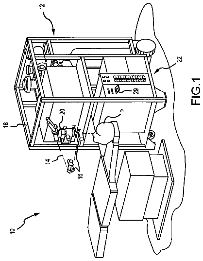
FIG. 1 is an illustration of a portion of a first embodiment of a system of the present invention;
FIGS. 2A to 2F depict side views of alternate embodiments of a distal tip region of a probe assembly;
FIG. 3A is an isometric view of one embodiment of the handle of the probe assembly of the present invention.
FIG. 3B is a longitudinal cross-section of one embodiment of a handle of the probe assembly of the present invention;
FIG. 4 is a perspective cut-away view of one embodiment of a distal tip region of a probe assembly of the present invention;
FIG. 5A is an axial cross-section through the distal tip region of the probe assembly shown in FIG. 4;
FIG. 5B is an axial cross-section through a more proximal portion of the distal tip region of the probe assembly shown in FIG. 4;
FIGS. 6A-6C are sectional views of various embodiments of a liquid-cooled distal tip region of a probe assembly;
FIG. 7 is a sectional view of an embodiment of a liquid-cooled distal tip region comprising an impedance monitoring tip;
FIG. 8 shows two probes placed within an intervertebral disc;
FIGS. 9A and 9B are sectional views of alternate embodiments of a liquid-cooled distal tip region illustrating various embodiments of a temperature sensing element;
FIG. 10 is a lateral view of a portion of a human spine;
FIGS. 11A and 11B show possible placements of two probe assemblies in an intervertebral disc;
FIG. 12A is a graph of temperature in a uniform tissue vs. relative distance using cooled and non-cooled probe assemblies; and
FIG. 12B is a graph of energy in a uniform tissue vs. relative distance using cooled and non-cooled probe assemblies.
Detailed description of the invention
With specific reference now to the drawings in detail, it is stressed that the particulars shown are by way of example and for purposes of illustrative discussion of some embodiments of the present invention only, and are presented in the cause of providing what is believed to be the most useful and readily understood description of the principles and conceptual aspects of the invention. In this regard, no attempt is made to show structural details of the invention in more detail than is necessary for a fundamental understanding of the invention, the description taken with the drawings making apparent to those skilled in the art how the several forms of the invention may be embodied in practice.
Before explaining at least one embodiment of the invention in detail, it is to be understood that the invention is not limited in its application to the details of construction and the arrangement of the components set forth in the following description or illustrated in the drawings. The invention is capable of other embodiments or of being practiced or carried out in various ways. Also, it is to be understood that the phraseology and terminology employed herein is for the purpose of description and should not be regarded as limiting.
For the purposes of this invention, a lesion refers to any effect achieved through the application of energy to a tissue in a patient's body, and the invention is not intended to be limited in this regard. Furthermore, for the purposes of this description, proximal generally indicates that portion of a device or system next to or nearer to a user (when the device is in use), while the term distal generally indicates a portion further away from the user (when the device is in use).
With reference to FIG. 1, a first embodiment of a system 100 of the present invention is shown. System 100 comprises a generator 102, a cable 104, first and second probe assemblies 106 (only one probe assembly is shown), one or more cooling devices 108, a pump cable 110, one or more proximal cooling supply tubes 112 and one or more proximal cooling return tubes 114. In this embodiment, generator 102 is a radio frequency (RF) generator, but may optionally be any energy source that may deliver other forms of energy, including but not limited to microwave energy, thermal energy, ultrasound and optical energy. Generator 102 may comprise a display means incorporated into said generator. Said display means may be operable to display various aspects of a treatment procedure, including but not limited to any parameters that are relevant to a treatment procedure, such as temperature, impedance, etc. and errors or warnings related to a treatment procedure. If no display means is incorporated into generator 102, generator 102 may comprise a means of transmitting a signal to an external display. In the first embodiment, generator 102 is operable to communicate with one more devices, for example with one or more of first and second probe assemblies 106 and the one or more cooling devices 108. Such communication may be unidirectional or bidirectional depending on the devices used and the procedure performed. An example of an RF generator that fulfills the above criteria is the Pain Management Generator (PMG) of Baylis Medical Company Inc. (Montreal, QC, Canada).
As illustrated in FIG. 1, in this first embodiment of a system of the present invention, a distal region 124 of cable 104 comprises a splitter 130 that divides cable 104 into two distal ends 136 as illustrated in FIG. 1 such that two probe assemblies 106 can be connected to cable 104. A proximal end 128 of cable 104 is connected to generator 102. This connection can be permanent, whereby, for example, the proximal end 128 of cable 104 is embedded within generator 102, or temporary, whereby, for example, the proximal end 128 of cable 104 is connected to generator 102 via an electrical connector. The two distal ends 136 of cable 104 terminate in connectors 140 operable to couple to probe assemblies 106 and establish an electrical connection between probe assemblies 106 and generator 102. In alternate embodiments (not shown), system 100 may comprise a separate cable for each probe assembly 106 being used to couple probe assemblies 106 to generator 102. Alternatively, splitter 130 may comprise more than two distal ends. Such a connector would be useful in embodiments where it would be desirable to connect more than two devices to generator 102, for example, if more than two probe assemblies are being used or if separate temperature sensors (i.e. not attached to the probe assemblies) are to be placed in a patient's body.
One or more cooling devices 108 may comprise any means of reducing a temperature of material located at and proximate to one or more of probe assemblies 106. In the first embodiment, one or more cooling devices 108 comprises two peristaltic pumps operable to circulate a fluid from the one or more cooling devices 108 through one or more proximal cooling supply tubes 112, probe assemblies 106, one or more proximal cooling return tubes 114 and back to the one or more cooling devices 108. The fluid may be water or any other suitable fluid. In alternate embodiments, one or more cooling devices 108 may comprise only one peristaltic pump or one or more electrothermal cooling devices or any other cooling means.
In the first embodiment, system 100 comprises a means of facilitating communication between the one or more cooling devices 108 and generator 102, and one or more cooling devices 108 is operable to communicate at least uni-directionally and optionally bi-directionally, with generator 102. In this way, feedback control is established between the one or more cooling devices 108 and the generator 102. The feedback control of the first embodiment of the present invention involves generator 102, first and second probe assemblies 106 and the one or more cooling devices 108, although any feedback between any two devices is within the scope of the present invention. The feedback control may be implemented, for example, in a controller or control module which may be a component of generator 102. In this embodiment, generator 102 is operable to communicate bi-directionally with first and second probe assemblies 106 as well as with the one or more cooling devices 108. In the context of this invention, bi-directional communication refers to the capability of a device to both receive a signal from and send a signal to another device.
As an example of feedback control in system 100 of the present invention, generator 102 may receive temperature measurements from one or both of first and second probe assemblies 106. Based on the temperature measurements, generator 102 may perform some action, such as modulating the power that is sent to first and/or second probe assemblies 106. Thus, both probe assemblies 106 may be individually controlled based on their respective temperature measurements. For example, power to each of the probe assemblies could be increased when a temperature measurement is low or decreased when a measurement is high. This variation of power may be different for each probe assembly. In some cases, generator 102 may terminate power to one or more probe assemblies 106. Thus, generator 102 may receive a signal (e.g. temperature measurement) from one or both of first and second probe assemblies 106, determine the appropriate action, and send a signal (e.g. decreased or increased power) back to one or both of first and second probe assemblies 106. Alternatively, generator 102 may send a signal to the one or more cooling devices 108 to either increase or decrease the flow rate or degree of cooling being supplied to one or both of first and second probe assemblies 106.
Alternatively, if one or more cooling devices 108 comprises one or more peristaltic pumps, the one or more pumps may communicate a fluid flow rate to generator 102 and may receive communications from generator 102 instructing the pumps to modulate this flow rate. In some instances, the one or more peristaltic pumps may respond to generator 102 by changing the flow rate or turning off for a period of time. With cooling devices 108 turned off, any temperature sensing elements associated with probe assemblies 106 would not be affected by the cooling fluid allowing a more precise determination of the surrounding tissue temperature to be made. In addition, when using more than one probe assembly 106, the average temperature or a maximum temperature in the temperature sensing elements associated with probe assemblies 106 may be used to modulate cooling.
In other embodiments, the one or more cooling devices 108 may reduce the rate of cooling or disengage depending on the distance between the probe assemblies 106. For example, when the distance is small enough such that a sufficient current density exists in the region to achieve a desired temperature, little or no cooling may be required. In such an embodiment, energy is preferentially concentrated between first and second energy delivery devices 192 through a region of tissue to be treated, thereby creating a strip lesion. A strip lesion is characterized by an oblong volume of heated tissue that is formed when an active electrode is in close proximity to a return electrode of similar dimensions. This occurs because at a given power, the current density is preferentially concentrated between the electrodes and a rise in temperature results from current density.
One or more cooling devices 108 may also communicate with generator 102 in order to alert generator 102 to one or more possible errors and/or anomalies associated with one or more cooling devices 108. For example, if cooling flow is impeded or if a lid of the one or more cooling devices 108 is opened. Generator 102 may then act on the error signal by at least one of alerting a user, aborting the procedure, and modifying an action.
In still other embodiments, generator 102 may communicate with only one of the one or more cooling devices 108 or communication between devices may be unidirectional. For example, the one or more cooling devices 108 may be operable to receive incoming signals from generator 102 but not to send signals back to generator 102. In addition to the aforementioned feedback systems, generator 102 may respond to Somatosensory evoked potentials (SSEP)/Electromyogram (EMG) measurements or some other measure of patient response to a treatment procedure. Many variations in feedback control may exist in a system of the present invention, and the invention is not limited in this regard.
As illustrated in FIG. 1, the means of facilitating communication between the one or more cooling devices 108 and generator 102 may take the form of a pump cable 110 electrically connecting generator 102 to the one or more cooling devices 108. In other embodiments, generator 102 and the one or more cooling devices 108 may be connected with an RS-232 cable, a fiber optic cable, a USB cable, a Firewire.TM. (ieee 1394) cable or other means of electrical coupling. In yet further embodiments, communication between generator 102 and the one or more cooling devices 108 may be achieved using some other communication protocol including but not limited to infrared, wireless, Bluetooth.TM. and others and the invention is not limited in this regard.
In the first embodiment of a system of the invention as illustrated in FIG. 1, the one or more proximal cooling supply tubes 112 comprise proximal supply tube connectors 116 at the distal ends of the one or more proximal cooling supply tubes 112. Additionally, the one or more proximal cooling return tubes 114 comprise proximal return tube connectors 118 at the distal ends of the one or more proximal cooling return tubes 114. In the first embodiment, proximal supply tube connectors 116 are female luer-lock type connectors and proximal return tube connectors 118 are male luer-lock type connectors although other connector types are intended to be within the scope of the present invention.
In the first embodiment of a system of the present invention and referring still to FIG. 1, probe assembly 106 comprises a proximal region 160, a handle 180, a hollow elongate shaft 184 and a distal tip region 190 comprising one or more energy delivery devices 192. Proximal region 160 comprises distal cooling supply tube 162, distal supply tube connector 166, distal cooling return tube 164, distal return tube connector 168, probe assembly cable 170 and probe cable connector 172. In this embodiment, distal cooling supply tube 162 and distal cooling return tube 164 are flexible to allow for greater maneuverability of probe assemblies 106, but alternate embodiments with rigid tubes are possible.
The description continues in the full USPTO document.
 Lapsed, fee not paid12 drawings