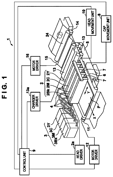
Lapsed, fee not paid17 drawings
Industrial Equipment · US 8,740,323 B2
Viscosity modulated dual feed continuous liquid ejector
A continuous liquid ejector includes a structure including a wall.
US 8,740,336 B2 · Assignee: Canon Kabushiki Kaisha · Inventors: Fujimoto; Yasunori et al.
Sheet 1 of 18 from the published document. All sheets in the USPTO PDF
An ink jet printing apparatus and an ink jet printing method, whereby high-permeation ink and low-permeation ink are employed to prevent a reduction in optical density is provided. The ink jet printing apparatus controls ejection of ink from print heads, so that only low-permeation ink is ejected onto the edge area of a print medium that is adjacent to a non-printing area, and this time, high-permeation ink is not employed. Further, the ink jet printing apparatus controls ejection of ink from the print heads, so that both low-permeation ink and high-permeation ink are employed for the non-edge area that is adjacent to the edge area, and to perform printing, the low-permeation ink is ejected onto the non-edge area prior to the high-permeation ink.
At present, printing apparatuses that eject ink droplets from a print head to perform printing has been widely employed as output apparatuses. In a printing apparatus that employs this system, there is a printing apparatus that ejects ink droplets from ejection ports that are formed in a print head, and forms dots on a print medium to print an image. For substantially filling a specific predetermined area of a print medium with a single color, ink dots are formed in that area by ejecting ink droplets at a high dot print density. However, in a case wherein too many ink droplets are ejected into the print area of predetermined size, ink bleeding occurs both inside and outside the print area, so that a clean outline of a printed image can not be obtained. To resolve this problem, in Japanese Patent Laid-Open No. 2002-113850 an ink jet printing apparatus is disclosed for which a print area i
1 of 18 drawing sheets so far from the published document, cropped to the drawing. Every sheet is in the USPTO PDF.
What the patent claimed, word for word. All of it is now free to use.
The present invention relates to an ink jet printing apparatus and an inkjet printing method employed for printing images by ejecting ink onto a print medium.
At present, printing apparatuses that eject ink droplets from a print head to perform printing has been widely employed as output apparatuses. In a printing apparatus that employs this system, there is a printing apparatus that ejects ink droplets from ejection ports that are formed in a print head, and forms dots on a print medium to print an image. For substantially filling a specific predetermined area of a print medium with a single color, ink dots are formed in that area by ejecting ink droplets at a high dot print density. However, in a case wherein too many ink droplets are ejected into the print area of predetermined size, ink bleeding occurs both inside and outside the print area, so that a clean outline of a printed image can not be obtained.
To resolve this problem, in Japanese Patent Laid-Open No. 2002-113850 an ink jet printing apparatus is disclosed for which a print area is divided into an outer area and an inner area, and the ink employed for printing each of the printing areas differs, depending on which area is to be printed. According to the printing apparatus disclosed in Japanese Patent Laid-Open No. 2002-113850, for the outer area, ink having a relatively low permeation rate (ink that relatively slowly permeates a print medium; hereinafter referred to as low-permeation ink) is employed to form dots, while for the inner area, ink having a relatively high permeation rate (ink that relatively rapidly permeates a print medium; hereinafter referred to as high-permeation ink) and the low-permeation ink are employed for form dots. Since the two types of ink, which have different permeation rates, are employed for printing the inner area, the period required for a print medium to dry can be reduced, compared with when only low-permeation ink having a low permeation rate is employed for printing, and as a result, the printing speed can be increased. Furthermore, compared with when only high-permeation ink is employed for printing the inner area, ink bleed can be reduced, and degradation of the quality of a printed image can be avoided.
When the printing apparatus disclosed in Japanese Patent Laid-Open No. 2002-113850 is used for printing, two types of ink dots having different permeation rates are alternately formed, in a staggered pattern, into the inner area. That is, in the inner area, dots of high-permeation ink and dots of low-permeation ink coexist. However, in Japanese Patent Laid-Open No. 2002-113850, it states simply that dots of the two types of ink, which have different permeation rates, are alternately formed in the inner area of an image being printed by the printing apparatus, and the order in which these two types of ink are ejected to form dots on a print medium is not specified. Therefore, it may logically be inferred that low-permeation ink droplets will be ejected into the print area after high-permeation ink droplets have been ejected. In such a case, the color component, such as a dye or a pigment, of the high-permeation ink deposited on the print medium may be drawn deep into the print medium, and the density of a dot could thereby be decreased. Therefore, the density of a part of a printed image may be insufficient, and the quality of the printed image degraded. This problem occurs when a dye is employed as the color material for an ink, but occurs more frequently when a pigment is employed as the color material.
While taking the above described problem into account, one objective of the present invention is to provide an ink jet printing apparatus, and an ink jet printing method, for performing printing using both high-permeation ink and low-permeation ink while a reduction in optical density is prevented.
According to an aspect of the present invention, there is provided an inkjet printing apparatus comprising: a print head being able to eject first ink and second ink, the color of which is similar to the color of the first ink and having higher permeation than the first ink, and used for printing an image to the print medium; and a printing controller for controlling ejection of the first ink and the second ink from the print heads, so that only the first ink is ejected and the second ink is not employed for printing in an edge area, that is adjacent to an area where the first ink and the second ink is not ejected, of a printing area corresponding to an area to be printed by at least one of the first ink or the second ink on the print medium, and both the first ink and the second ink are employed, and the first ink is ejected prior to the second ink for printing in a non-edge area that is adjacent to the edge area, of the printing area.
According to an aspect of the present invention, there is provided an ink jet printing method, whereby a print head being able to eject first ink and second ink, the color of which is similar to the color of the first ink and having higher permeation than the first ink, and used for printing an image to the print medium, the ink jet printing method comprising: a printing control step for controlling ejection of the first ink and the second ink from the print heads, so that only the first ink is ejected and the second ink is not employed for printing in an edge area that is adjacent to an area where the first ink and the second ink is not ejected, of a printing area corresponding to an area to be printed by at least one of the first ink or the second ink on the print medium, and both the first ink and the second ink are employed, and the first ink is ejected prior to the second ink for printing in a non-edge area that is adjacent to the edge area of the printing area.
Since the ink jet printing apparatus and the ink jet printing method of this invention can prevent a reduction in optical density, degradation in the quality of a printed image can be avoided.
Further features of the present invention will become apparent from the following description of exemplary embodiments (with reference to the attached drawings).
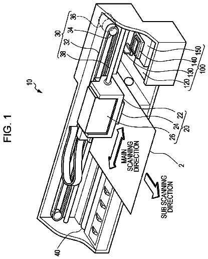
FIG. 1 is a schematic perspective view of an inkjet printing apparatus according to a first embodiment of the present invention;
FIG. 2A is a schematic plan view of print heads employed for the ink jet printing apparatus in FIG. 1;
FIGS. 2B and 2C are diagrams for explaining the order in which ink droplets are ejected by the print heads in FIG. 2A;
FIG. 3 is a schematic block diagram illustrating the arrangement of a control system for printing performed by the ink jet printing apparatus in FIG. 1;
FIG. 4 is a functional block diagram illustrating a schematic arrangement for data transmission during the image data processing performed by an image processing system, which includes the ink jet printing apparatus in FIG. 1 and a host PC;
FIG. 5 is a detailed block diagram illustrating a schematic arrangement for transmission of data used to explain the edge processing performed in the block diagram in FIG. 4;
FIGS. 6A to 6L are explanatory diagrams for explaining a data distribution process for allocating, for the individual print areas, data that are to be printed by corresponding print heads in the first embodiment;
FIG. 7 is a diagram showing the relationship between FIGS. 7A and 7B;
FIGS. 7A and 7B are block diagrams illustrating a schematic arrangement for transmission of data used to explain the edge processing performed, during a printing operation, by an ink jet printing apparatus according to a second embodiment of the present invention;
FIGS. 8A to 8L are explanatory diagrams for explaining a data distribution process for allocating, for the individual print areas, data that are to be printed in the second embodiment;
FIGS. 9A to 9L are explanatory diagrams for explaining a data distribution process for allocating, for the individual print areas, print data that are to be printed in a third embodiment of the present invention;
FIG. 10A is a schematic plan view of print heads employed for an ink jet printing apparatus according to a fourth embodiment of the present invention;
FIGS. 10B and 10C are explanatory diagrams for explaining the order in which ink is ejected by the print heads in FIG. 10A;
FIG. 11 is an explanatory diagram illustrating a relationship between the positions of the print heads and the position of the targeted print area of a print medium when printing is to be performed using the print heads in FIGS. 10A to 10C;
FIG. 12 is a diagram showing the relationship between FIGS. 12A and 12B;
FIGS. 12A and 12B are block diagrams illustrating a schematic arrangement for the transmission of data to explain the edge processing performed during the printing operation of the ink jet printing apparatus according to the fourth embodiment;
FIGS. 13A to 13O are explanatory diagrams for explaining a data distribution process for allocating, for the individual print areas, data that are to be printed in the fourth embodiment;
FIGS. 14A and 14B are explanatory diagrams for explaining the order in which ink is ejected by print heads that are employed for printing in the fourth embodiment;
FIGS. 15A to 15L are explanatory diagrams for explaining a data distribution process for allocating, for the individual print areas, data that are to be printed according to a fifth embodiment of the present invention;
FIG. 16A is a schematic plan view of print heads employed for an ink jet printing apparatus according to a sixth embodiment of the present invention; and
FIGS. 16B and 16C are explanatory diagrams for explaining the order in which ink is ejected by the print heads in FIG. 16A.
An ink jet printing apparatus according to the present invention will now be described while referring to the accompanying drawings.
First Embodiment
FIG. 1 is a schematic perspective view of the arrangement of a color inkjet printing apparatus according to a first embodiment of the present invention. The ink jet printing apparatus stores six ink fluids (black (low-permeation ink), black (high-permeation ink), black (low-permeation ink), cyan, magenta and yellow: Ke, Km, Ke, C, M and Y) in ink tanks 207 to 212 so as to supply these ink fluids from these six ink tanks 207 to 212 to print heads 201 to 206. The print heads 201 to 206 are provided in correlation with the six ink fluids to eject ink supplied from the ink tanks 207 to 212. Of the six print heads 201 to 206, the print heads 201, 202 and 203 are employed to eject black ink. Further, in this embodiment, of these print heads that eject black ink, the print heads 201 and 203 eject ink that relatively slowly permeates a print medium (hereinafter referred to as a low-permeation ink), and the print head 202 ejects ink that relatively rapidly permeates (hereinafter referred to as high-permeation ink).
During a printing operation, conveying rollers 103 and auxiliary rollers 104, which are rotated together, sandwich and convey a print medium (a print sheet) 107. Further, the conveying rollers 103 and the auxiliary rollers 104 also hold the print medium 107. Concurrently, a carriage 106, on which the ink tanks 207 to 212 and the print heads 201 to 206 can be mounted, reciprocates in a direction X. Then, while the carriage 106 reciprocates, ink is ejected by the print heads and an image or images are printed on the print medium 107. During a non-printing operation, such as a recovery operation for the print heads 201 to 206, the carriage 106 is moved to and remains at a home position h, described by broken lines in FIG. 1.
When a printing start instruction is entered, the carriage 106, waiting at the home position h in FIG. 1, is moved away from the position h and begins to reciprocate, carrying the print heads 201 to 206 in the direction X. Furthermore, while the carriage 106 is reciprocating, the print heads 201 to 206 eject ink onto the print medium 107 to print an image or images. When the print heads 201 to 206 have completed one pass (one scan), printing have been performed for a portion for which the width is equivalent to the range wherein the ejection ports of the print heads 201 to 206 are arranged.
When printing has been performed in conjunction with scanning performed by the carriage 106 in the main scan direction (positive X direction), the carriage 106 moves in the main scan direction (negative X direction) toward the home position h. During this movement, the print heads 201 to 206 are again moved while ejecting ink onto the print medium 107. During a period extending from the end of a preceding scan to the start of a succeeding scan, the conveying rollers 103 are rotated and convey the print medium 107 in a sub-scan direction (direction Y) that crosses the main scan direction. When the scanning performed by the print heads 201 to 206 and the conveying of the print medium 107 are repeatedly performed, in the described manner, printing of an image on the print medium 107 is completed. This printing operation, performed by ejecting ink from the print heads 201 to 206 is performed by control means that will be described later.
In the above example arrangement, the ink tanks 207 to 212 and the print heads 201 to 206 are mounted as separate units on the carriage 106. However, an arrangement may be employed wherein an integrated cartridge that includes the ink tanks 207 to 212 and the print heads 201 to 206 is mounted on the carriage 106. Further, an arrangement may also be employed wherein a multi-color integrated print head that can eject multiple colors of ink is mounted on a carriage.
A data generation method employed for the ink jet printing apparatus will now be described. FIG. 3 is a schematic block diagram illustrating the arrangement of a printing control system for the ink jet printing apparatus in FIG. 1. An ink jet printing apparatus 600 is connected via an interface 400 to a data supply apparatus, such as a host computer (hereinafter referred to as a host PC) 1200. Various data and control signals associated with printing, transmitted from the data supply apparatus, are supplied to a printing controller 500 of the ink jet printing apparatus 600. The printing controller 500 controls motor drivers 403 and 404 and head drivers 405, which will be described later, based on control signals entered via the interface 400. Furthermore, the printing controller 500 processes input image data and a signal received from a head type signal generation circuit 406, which will be described later. A conveying motor 401 is used to rotate the conveying rollers 103, which convey the print medium 107. A carriage motor 402 reciprocally moves the carriage 106 on which the print heads 201 to 206 are mounted. The motor drives 403 and 404 drive the conveying motor 401 and the carriage motor 402, respectively, and the print heads 201 to 206 are driven by head drivers 405, the number of which is equivalent to that of the print heads 201 to 206. Furthermore, the head type signal generation circuit 406 transmits to the printing controller 500 a signal indicating the type and number of the print heads 201 to 206 that are mounted on the carriage 106.
FIG. 4 is a functional block diagram illustrating a schematic arrangement for image data processing performed by an image processing system that includes the ink jet printing apparatus and the host PC. The printing controller 500 of the ink jet printing apparatus 600 processes data that are transmitted, via the interface 400, by the host PC 1200, wherein a printer driver is installed.
The host PC 1200 receives input image data 1000 from an application program, and performs for the input image data 1000 a rendering process 1001 at a resolution of 1200 dpi (dots/inch). And as a result, multi-valued print RGB data 1002 are generated. In this embodiment, the multi-valued print RGB data 1002 is 256 valued data, and the obtained multi-valued print RGB data 1002 is transmitted to the printing controller 500 of the ink jet printing apparatus 600. The printing controller 500 performs a color conversion process 1007 to convert the multi-valued print RGB data 1002 into multi-valued (256 valued) KCMY data 1008. Then, a quantization process 1009 (e.g., error diffusion) is performed to quantize (binarize) the multi-valued (256 valued) KCMY data 1008, and as a result, the binary KCMY data are obtained. In this embodiment, binary KCMY data are generated that have a resolution of 1200 dpi.
Edge processing is performed for black data in the binary data. FIG. 5 is a diagram showing the edge processing. First, a non-edge detection process 2001 is performed. Of the binary black data, data for a non-edge portion, i.e., non-edge area data 2003, are generated. The binary black data that is not pertinent to non-edge area data is regarded as edge area data 2103. The edge portion is the edge area adjacent to a non-print area where printing is not to be performed, and the non-edge area surrounded by the edge area is a non-edge portion. In this embodiment, of the binary black data, one pixel (one dot) is selected from the outermost portion (external edge) of the targeted print area, and is defined as an edge pixel that is to be printed to form the edge portion. The other data is employed for non-edge area data.
When the edge area data and the non-edge area data are generated, ink is ejected for printing based on the edge area data and non-edge area data. The order in which ink is ejected onto a print medium will now be described while referring to FIGS. 2A to 2C.
Of the print heads 201 to 206 in FIG. 1, the print heads 201 to 203 that eject black ink are shown in FIG. 2A. Ink to be ejected from the print heads 201, 203 is low-permeation ink (ink that is relatively slow to permeate a print medium; hereinafter referred to as low-permeation ink) (first ink). Ink to be ejected from the print head 202 is high-permeation ink (ink that is relatively fast to permeate a print medium; hereinafter referred to as high-permeation ink) (second ink). The low-permeation ink and the high-permeation ink are visually identified as the same color when these inks are printed on a print medium. The ink jet printing apparatus of this embodiment prepares the print head 201 for ejecting low-permeation ink (first print head), the print head 202 for ejecting high-permeation ink (second print head) and the print head 203 for ejecting low-permeation ink (third print head). That is, in this embodiment, ejection port arrays that are to eject low-permeation ink (first and third ejection port arrays) and an ejection port array that is to eject high-permeation ink (second ejection port array) are provided as ejection port arrays. In this embodiment, a resolution of the ejection ports in an ejection port array arranging direction of the print head is 1200 dpi.
As shown in FIG. 2B, when the print heads are moved in the direction -X, droplets of low-permeation ink (211 in FIG. 2B) are ejected, by the print head 201, onto both the non-edge area (non-edge portion) and the edge area (edge portion). Thereafter, droplets of high-permeation ink (212 in FIG. 2B) are ejected, by the print head 202, onto the non-edge area (non-edge portion). Sequentially, then, droplets of low-permeation ink (213 in FIG. 2B) are ejected, by the print head 203, onto the edge area (edge portion). Then, while moving the print heads in the direction X, as shown in FIG. 2C, droplets of low-permeation ink (223 in FIG. 2C) are ejected, by the print head 203, onto both the non-edge area (the non-edge portion) and the edge area (the edge portion). Then, droplets of high-permeation ink (222 in FIG. 2C) are ejected, by the print head 202, onto the non-edge area (the non-edge portion). Thereafter, droplets of low-permeation ink (221 in FIG. 2C) are ejected, by the print head 201, onto the edge area (the edge portion).
In the printing process for the non-edge area, droplets of the high-permeation ink 212, ejected by the print head 202 during the movement in the direction -X, landed so they overlapped dots of the low-permeation ink 211 that were formed previously. Further, droplets of the high-permeation ink 222, ejected by the print head 202 during movement in the direction X, landed so they overlapped dots of the low-permeation ink 223 that were formed previously. Since the low-permeation inks 211 and 223 are slow to permeate, i.e., the permeation rate for these inks is low, and the dots of the low-permeation inks 211 and 223 remain on the surface of the print medium until droplets of the high-permeation inks 212 and 222 have landed on the print medium. Then, when the low-permeation ink 211 and 223 and the high-permeation inks 212 and 222 on the surface of the print medium blend, the permeation rates of the two inks are averaged. At this time, the permeation rate is increased, and exceeds the permeation rate for the portion that was printed using only the low-permeation ink. Specifically, when the non-edge area of an image is printed first using low-permeation ink having a low permeation rate, and is then printed using a high-permeation ink having a high permeation rate, color materials permeate the print medium better than when printing is performed using only the low-permeation ink, and rub resistance and bleed fastness are improved.
As described above, for printing the non-edge area of a printing image, the ejection of low-permeation ink is performed prior to the ejection of high-permeation ink (non-edge area printing sequence), so that the low-permeation ink and the high-permeation ink on the print medium at least contact each other.
For printing the edge area, ejection of ink is performed by the print heads 201 and 203 that eject low-permeation ink (edge area printing sequence).
In a case wherein an ink color material in an ink being used to print an image is raised too much on the surface of a print medium, and something, such as a finger, inadvertently touches the excessively raised portion formed by the color material on the print medium, there is a possibility that the color material will be smudged and the quality of the image debased. Further, if an ink color material in an ink being used to print images is raised too much on the surface of a print medium, and the characters are subsequently traced using a marker pen, a possibility is that the marker pen will cause the color material at the raised portions to bleed, and the quality of the printed images degraded. However, when the color material or materials appropriately permeate the print medium, the excessive raising of ink on the surface of the print medium does not occur, and when the print medium is touched by a finger or printed images are traced using a marker pen, the printed image or images will not be smudged, and a high image quality can be maintained for the image or images.
Further, when printing is performed for the non-edge area according to the order in which low-permeation ink and high-permeation ink are ejected, a greater optical density for a printed image is provided than when high-permeation ink ejection is performed before the slow-drying, or when only the ejection of high-permeation ink is performed.
Printing for the non-edge area data 2003 is performed using both the print heads that eject low-permeation ink and the print heads that eject high-permeation ink. As for the ejection of low-permeation ink, the print heads employed for printing are changed, depending the direction in which scanning is performed by the entire print head unit and the carriage. When the print head unit moves in the direction X, the print head 203 ejects the low-permeation ink 223, as shown in FIG. 2C, or when the print head unit moves in the direction -X, the print head 201 ejects the low-permeation ink 211, as shown in FIG. 2B. In this manner, printing is performed by allocating the ejection of the low-permeation ink to two print heads. As a result, as shown in FIG. 2A, regardless of the scan direction for the print head unit, either the print head 201 or 203, which ejects low-permeation ink, is positioned, in the scan direction, in front of the print head 202 that ejects high-permeation ink. Therefore, the ink jet printing apparatus performs printing by first ejecting ink from the print head 201 or the print head 203, and then from the print head 202. That is, regardless of the scan direction for the print heads, printing is initiated using low-permeation ink, and is continued, using high-permeation ink thereafter. As described above, when the print head 201 is located forward in the scan direction, the printing sequence (first printing sequence) is employed for ejecting ink from the print heads 201 and 202, and for printing the non-edge area. And when the print head 203 is located forward in the scan direction, the printing sequence (second printing sequence) for ejecting ink from the print heads 202 and 203 is employed for printing the non-edge area.
In this embodiment, two print heads, both of which eject low-permeation ink, are employed for printing the non-edge area data 2003; however, only one print head may be so employed. For example, when the print heads are moved in the direction X, only the print head 201 may eject ink to print the non-edge area data 2003. Furthermore, when the print heads are moved in the direction -X, only the print head 203 may eject ink for printing the non-edge area data 2003. As obtained effects, bleeding of the non-edge area where high-permeation ink droplets first landed is not actually visible.
The data distribution process performed by allocating data to the print heads 201, 202 and 203 for the individual areas will now be described while referring to FIGS. 6A to 6L. One cell in an area indicates one pixel for print data, and one ink dot is ejected for one pixel. FIGS. 6A to 6L are explanatory diagrams for the process for allocating data to the print heads 201 to 203, which will be described later, and FIGS. 6C, 6G and 6J correspond to images printed by the print head 201. Similarly, FIGS. 6D, 6H and 6K correspond to images printed by the print head 202, and FIGS. 6E, 6I and 6L correspond to images printed by the print head 203. FIG. 6A is a diagram showing the entire print data for the targeted print area employed in this embodiment. The targeted print area in FIG. 6A represents an image that includes the edge area, which is an area inward from the outer edge a distance equivalent to a predetermined number of pixels, and the non-edge area that is located inside the edge area. Broken lines laterally shown in the center in FIGS. 6A to 6L indicate the boundary between areas where the scan direction of the print heads differs. The portions above the broken lines are pixels printed when the scan direction of the print heads is the direction X (right in FIGS. 6A to 6L), and the portions below the broken lines are pixels printed when the scan direction of the print heads is the direction -X (left in FIGS. 6A to 6L). When the non-edge detection process 2001 is performed, binary print data are employed to generate the non-edge area data 2003, which are employed for forming pixels in FIG. 6F, and the edge area data 2103, which are employed for forming pixels in FIG. 6B.
The process for printing the edge area data 2103 image shown in FIGS. 6B to 6E will now be described. Printing for the edge area data 2103 shown in FIG. 6B is performed while employing the print heads 201 and 203 that eject low-permeation ink. When the print head unit is moved in the direction X, the print head 203 is located in front of the print head 201, in the scan direction. Therefore, during one scan performed for the printing of the targeted print area, the upper half of an image shown in FIG. 6E is printed, by the print head 203, on a predetermined area, and sequentially thereafter, the upper half of the image shown in FIG. 6C is printed on the same area by the print head 201. When the scanning in the direction X has been completed, the scan direction is reversed, and the print head unit begins to move in the direction -X. Then, as the print heads are moved in the direction -X, the print head 201 is located in front of the print head 203, in the scan direction. Therefore, the lower half of the image shown in FIG. 6C is printed on a predetermined area by the print head 201, and sequentially following, the lower half of the image in FIG. 6E is printed on the same area by the print head 203.
The process for printing the non-edge area data 2003 in FIGS. 6F to 6I will now be described. The non-edge area data 2003 shown in FIG. 6F are image print data for an area obtained by excluding, from the print data for an image shown in FIG. 6A, the portion for the edge area data 2103.
Thus, the non-edge area data 2003 image in FIG. 6F is printed by employing both the print head 201, 203, which ejects low-permeation ink, and the print head 202, which ejects high-permeation ink. During this printing process, according to the established printing order for the ejection of ink onto the individual print areas for the non-edge area data 2003, printing performed using the high-permeation ink sequentially follows printing performed using the low-permeation ink.
When the print heads are moved in the direction X, printing is performed for the upper half of the area in FIGS. 6F to 6I. During this time, the print head 203 ejects low-permeation ink, and the print head 202 ejects high-permeation ink. At this time, in the scan direction, the print head 203 is located in front of the print head 201. Therefore, during a single scan, performed for the printing of the targeted print area, low-permeation ink is ejected onto a predetermined area by the print head 203, and sequentially thereafter, high-permeation ink is ejected onto the same area by the print head 202.
When scanning in the direction X has been completed, the scan direction is reversed and the print heads begin to move in the direction -X. While the print heads are being moved in the direction -X, printing is performed using the print head 201, which ejects low-permeation ink, and the print head 202, which ejects high-permeation ink. At this time, in the scan direction, the print head 201 is located in front of the print head 202. Therefore, during a single scan performed in the direction -X, for printing the targeted print area, low-permeation ink is ejected, by the print head 201, onto a predetermined area, and sequentially thereafter, high-permeation ink is ejected, by the print head 202, onto the same area. As described above, of the non-edge area data 2003 shown in FIG. 6F, data for the upper half portion that is to be printed during the X-directional scan is allocated to the print head 202, which ejects high-permeation ink, and the print head 203, which ejects low-permeation ink. The data allocated to the print head 202 is print data for the upper half portion of an image shown in FIG. 6H, whereas the data allocated to the print head 203 is print data for the upper half image shown in FIG. 6I. Further, of the non-edge area data 2003, data for the lower half portion that is to be printed during the -X directional scanning is allocated to the print head 201, which ejects low-permeation ink, and the print head 202, which ejects high-permeation ink. Furthermore, the data allocated to the print head 201 is print data for the lower half image shown in FIG. 6G, whereas the data allocated to the print head 202 is print data for the lower half portion of the image shown in FIG. 6H.
As a result, data to be printed by the individual print heads are as follows. Data printed by the print head 201 is the logical sum (FIG. 6J) of the edge area data in FIG. 6C and the non-edge area data in FIG. 6G. Data printed by the print head 202 is the logical sum (FIG. 6K) of the edge area data in FIG. 6D and the non-edge area data in FIG. 6H. And data printed by the print head 203 is the logical sum (FIG. 6L) of the edge area data in FIG. 6E and the non-edge area data in FIG. 6I.
The present invention also includes a program that employs the above described ink jet printing method, to control an ink jet printing apparatus, and permits the ink jet printing apparatus to eject ink onto a targeted print area on a print medium and to perform printing.
The following ink compositions are employed for this embodiment. The ratios of the individual components are represented using parts by mass (the total for all the components is 100 parts by mass).
(High-Permeation Ink)
TABLE-US-00001 Pigment dispersion 50 parts by mass Glycerine 10 parts by mass Polyethylene glycol 1000 1 part by mass Acetylenol E100 (trademark by Kawaken 1 part by mass Fine Chemicals Co., Ltd.) Water Remaining parts
(Low-Permeation Ink)
TABLE-US-00002 Pigment dispersion 50 parts by mass Glycerine 10 parts by mass Polyethylene glycol 1000 1 part by mass Acetylenol E100 (trademark by Kawaken Fine 0.03 parts by mass Chemicals Co., Ltd.) Water Remaining parts
The pigment dispersion described above was obtained through the following process.
[Pigment Dispersion]
Carbon black of 10 g, for which the surface area is 230 m.sup.2/g and the DBP absorption is 70 ml/100 g, and p-aminobenzoic acid of 3.41 g were properly mixed in water of 72 g, and thereafter, nitric acid of 1.62 g was dripped into the obtained mixture, which was then stirred at a temperature of 70.degree. C. After several minutes had elapsed, a solution wherein sodium nitrite of 1.07 g was dissolved in water of 5 g was added to the mixture, and the resultant mixture was stirred for one hour. The obtained slurry was filtered through qualitative Toyo Roshi filter paper No. 2 (produced by Advantis), and pigment particles were rinsed sufficiently and dried in an oven at a temperature of 90.degree. C., and thereafter, water was added to the pigment. As a result, an aqueous pigment solution having a pigment density of 10 parts by mass was prepared. When the above described method was employed, a pigment dispersion was obtained that contained anionically charged, self-dispersible carbon black, wherein a hydrophilic group was coupled to the surface via a phenyl group.
The ink composition employed for this embodiment is merely an example for which the present invention can be applied, and two types of ink that have similar colors and have different permeation rates may be employed.
The color material employed for this embodiment is called a self-dispersible pigment that includes a hydrophilic group attached to pigment particles. There is another type of color material, called a resin dispersed pigment, where a resin is attached to pigment particles and the hydrophilic group of the resin exhibits a water-soluble property. According to the study of the present inventors, the self-dispersible pigment is more appropriate for the present invention, but the effects of the present invention were also obtained using the resin dispersed pigment.
A difference in permeation between high-permeation ink and low-permeation ink is defined depending on the surface tension. The effects of the present invention could be obtained when the surface tension of high-permeation ink was smaller than the surface tension of low-permeation ink, and when the surface tension of high-permeation ink was between equal to or greater than 20 mN/m and equal to or smaller than 40 mN/m, and the surface tension of low-permeation ink was between equal to or greater than 40 mN/m and equal or smaller than 60 mN/m. In this embodiment, surfactant Acetylenol E100 (ethylene oxide-2, 4, 7, 9-tetramethyl-5-decyne-4, 7-diol)) (product name by Kawaken Fine Chemicals Co., Ltd.) was employed to control the surface tension. The permeation rates of high-permeation ink and the permeation of low-permeation ink are relatively changed using the surfactant; however, another solvent may be employed.
As described above, since the edge area (edge portion) is printed using low-permeation ink, bleeding of a printed image can be reduced, and the density of the image can be increased while degrading of the image quality is avoided. Furthermore, the non-edge area (non-edge portion) is printed by ejecting first low-permeation ink and then high-permeation ink, the permeation rate of the high-permeation ink in the print medium can be suppressed. Therefore, a large amount of the ink color material can be retained on the surface of the print medium, and the optical density of the non-edge area can be increased. Compared with when printing is performed only by using low-permeation ink, a probability that the ink color material is raised and maintained on the surface of the print medium is reduced. Therefore, a damage on a printed image and degrading of the image quality, which will occur when the hand of a user, or the other thing, touches the color material of ink that remains on the surface of the print medium, are also reduced. When the amount of ink that rises on the surface of the print medium is reduced, rub fastness and bleed fastness for a printed image can be improved.
Second Embodiment
The printing processing performed by an ink jet printing apparatus according to a second embodiment of the present invention will now be described. As for portions that correspond to those in the first embodiment, the same reference numerals used for the first embodiment are also provided to omit a description for these portions, and only different portions will be described below.
In the printing processing for the first embodiment, low-permeation ink is ejected to the edge portion, while as for the non-edge portion, low-permeation ink is ejected first on to the entire area, and then high-permeation ink is ejected on the same area to superimpose ink. In contrast, according to the second embodiment, the printing processing is performed by thinning out data partially for the edge portion and the non-edge portion in order to increase throughput. Sequentially, at the non-edge portion, dots of low-permeation ink and dots of high-permeation ink are superimposed and become complementary to each other, so that the overall printed image is obtained. In this embodiment, printing is so performed that the area printed using low-permeation ink and the area printed using high-permeation ink are adjacent to each other, at the non-edge portion.
For sequential ink ejection from individual ejection ports, a predetermined time interval is required for application of energy to the print heads for the ejection of ink. Further, after ink has been ejected, an ink refilling period is required for supplying ink to the individual nozzles. Furthermore, at each elapse of a predetermined time period, a period for transmitting a predetermined amount of print data to a storage area is required. The number of dots (hereinafter also referred to as a scanning resolution) one print head can print during one scan strongly depends on the structure of a print head. When an increase in the scanning resolution of a print head by changing of the structure of the print head is desired, the structure of the print head must be greatly changed, and the manufacturing cost of the ink jet printing apparatus raised accordingly.
The description continues in the full USPTO document.
About 6,746 words. The USPTO PDF has it with every drawing.
Fees are due 3.5, 7.5 and 11.5 years after grant. This patent expired on June 3, 2026, so the fee marked "not paid" was the one that went unpaid.
INK JET PRINTING APPARATUS AND INK JET PRINTING METHOD
Filed Jul 2011 · published Jan 2012Ink jet printing apparatus and ink jet printing method
Filed Jul 2011 · granted Jun 2014Earlier publications, parents and continuations. None of them can still be enforced, or this patent would not be listed.
Prior art cited by the examiner or applicant. Useful when you check your own idea for novelty.
Everything on this page comes from the documents linked above.