Lapsed, fee not paid12 drawings
Vehicles & Drones · US 8,740,228 B2
Dolly with wheel acceptance area
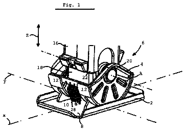
A dolly includes a deck having a support surface and a plurality of casters below the deck.
US 8,740,238 B2 · Assignee: SRAM, LLC · Inventors: Mickelson; Craig S.
Sheet 1 of 3 from the published document. All sheets in the USPTO PDF
A handlebar-steered suspension fork that includes an outer tube and an inner tube reciprocally slidable within the outer tube. The outer tube includes at least one radial load region and at least one transition region. A fiber-reinforced material is wrapped about at least one of the outer tube radial load regions and not wrapped about at least one of the outer tube transitions regions.
The present invention relates to handlebar-steered suspension forks, and more particularly, to a handlebar-steered suspension fork that includes a fiber-reinforced material wrapped about radial load regions of an outer tube of the fork and not wrapped about transition regions of the outer tube.
1 of 3 drawing sheets so far from the published document, cropped to the drawing. Every sheet is in the USPTO PDF.
What the patent claimed, word for word. All of it is now free to use.
The present invention relates to handlebar-steered suspension forks, and more particularly, to a handlebar-steered suspension fork that includes a fiber-reinforced material wrapped about radial load regions of an outer tube of the fork and not wrapped about transition regions of the outer tube.
The strength of a handlebar-steered suspension fork may be increased by selectively wrapping the fork with a fiber-reinforced material according to one embodiment of the present invention. The handlebar-steered suspension fork includes an outer tube and an inner tube reciprocally slidable within the outer tube. The outer tube includes at least one radial load region and at least one transition region. A fiber-reinforced material is wrapped about at least one of the outer tube radial load regions and not wrapped about at least one of the outer tube transition regions.
In one embodiment of the present invention, the fork includes a bushing disposed between the outer and inner tubes. The bushing is configured to transmit radial load from the inner tube to the radial load region of the outer tube. In another embodiment of the present invention, each of the outer tube radial regions is wrapped with the fiber-reinforced material.
These and other features and advantages of the present invention will be more fully understood from the following description of one or more embodiments of the invention, taken together with the accompanying drawings.
In the drawings:
FIG. 1 is perspective view of a suspension fork according to one embodiment of the present invention;
FIG. 2 is a partial cross-sectional view of a leg of the suspension fork of the FIG. 1;
FIG. 3 is an enlarged view of a portion of the leg of FIG. 2; and
FIG. 4 is a perspective of view of a suspension fork according to another embodiment of the present invention.
FIGS. 1-3 illustrate a suspension fork 10 that includes fiber-reinforced material selectively wrapped about the fork 10 according to one embodiment of the present invention. Looking to FIG. 1, the suspension fork 10 includes an upper housing 12 and a lower housing 14. The upper housing 12 includes a crown 16 connected to a steerer tube 18 and inner tubes 20, 22. The lower housing 14 includes outer tubes 24, 26, an arch 28 and dropouts 30, 32. The arch 28 connects the outer tubes 24, 26 for increased rigidity of the lower housing 14. In this embodiment, the outer tubes 24, 26 and the arch 28 embody a single piece, however, the tubes 24, 26 and the arch 28 may be separate pieces fastened together. The dropouts 30, 32 connect the fork 10 to a wheel axle (not shown). The inner tubes 20, 22 are reciprocally slidable within the outer tubes 24, 26, respectively, each inner and outer tube pairing forming a leg 25, 27 of the suspension fork 10. The legs 25, 27 of the fork 10 may include a damping system 34 and a spring system 35. The outer tubes 24, 26 include radial load regions 37 and transition regions 39.
Looking to FIGS. 2 and 3, the leg 27 includes a first bushing 68 and a second bushing 70 positioned between the inner and outer tubes 24, 26. The bushings 68, 70 are configured to transmit radial load from the inner tube 24 to the radial load regions 37 of the outer tube 26. As the inner and outer tubes are loaded laterally with respect to the direction of suspension travel, the inner tube applies a radial or prying load to the outer tube, the outer tube resisting deflection under hoop and bending stress. To further resist the prying loads of the inner tube, without adding extraneous weight, a fiber-reinforced material 72 is selectively wrapped about the outer tube 26 at the radial load regions 37 of the outer tube 26 and not wrapped about the transition regions 39 of the outer tube 26. Further, the bushings 68, 70 inhibit wear of the inner and outer tubes 24, 26 by preventing direct contact therebetween. The bushings 68, 70 are typically fixed to the outer tube 26, but may alternatively be fixed to the inner tube 24.
In another embodiment of the present invention, typically in suspension forks with shorter travel, the fiber-reinforced material 72 may extend continuously between proximate or overlapping radial load regions 37 of the outer tube 26 (see FIG. 4). In similar embodiments, a single bushing may be used instead of paired bushings 68, 70.
The fiber-reinforced material 72 increases the hoop strength of the outer tube 26 in these radial load regions, resulting in greater stiffness and load capacity. Further, the fiber-reinforced material 72 supports the outer tube 26 during installation and sizing of the bushings 68, 70, thereby preventing splitting of the outer tube 26 and resulting in more stable bushing performance. The fiber-reinforced material may include various layers of materials. The inner-most layer may be an adhesive that bonds the wrap to the outer leg. The next layer may be a glass, insulative layer preventing galvanic corrosion with additional layers of unidirectional and/or weave materials for structural strength. Lastly, an outer-most layer may provide a cosmetic finished look. The structural layers may be carbon, glass, Kevlar or of a similar fibrous material.
While this invention has been described by reference to one or more embodiments, it should be understood that numerous changes could be made within the spirit and scope of the inventive concepts described. Accordingly, it is intended that the invention not be limited to the disclosed embodiment, but that it have the full scope permitted by the language of the following claims.
About 948 words. The USPTO PDF has it with every drawing.
Fees are due 3.5, 7.5 and 11.5 years after grant. This patent expired on June 3, 2026, so the fee marked "not paid" was the one that went unpaid.
Fiber-Reinforced Wrapped Handlebar-Steered Suspension Fork
Filed Aug 2007 · published Mar 2009Fiber-reinforced wrapped handlebar-steered suspension fork
Filed Aug 2007 · granted Jun 2014Earlier publications, parents and continuations. None of them can still be enforced, or this patent would not be listed.
Prior art cited by the examiner or applicant. Useful when you check your own idea for novelty.
Everything on this page comes from the documents linked above.