Lapsed, fee not paid7 drawings
Telecom & Networks · US 8,737,273 B1
Systems and methods for collaborative communication
Systems and methods for dynamically configuring and optimizing a multimedia conference session.
US 8,737,286 B2 · Assignee: Panasonic Corporation · Inventors: Golitschek Edler Von Elbwart; Alexander et al.
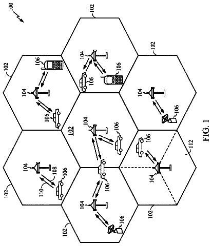
Sheet 1 of 21 from the published document. All sheets in the USPTO PDF
The invention relates to the definition of a structure of a sub-frame for transmission from a Node B to at least one relay node in a communication system. Furthermore, the invention is also related to the operation of Node B and relay node regarding the generation, transmission and reception of such special sub-frame format. The invention is inter alia applicable to a 3GPP LTE-A system as standardized by the 3rd Generation Partnership Project (3GPP). The invention suggests a new structure for a sub-frame that is capable of conveying control information and/or data for a relay node to the relay node essentially independent from propagation delays. The structure of the sub-frame takes into account propagation delays of the radio signal from Node B to relay node, in that control information and/or data for a relay node is transmitted from the Node B on OFDM symbols that can be expected to be received by the relay node.
3GPP Long Term Evolution (3GPP LTE) Third-generation mobile systems (3G) based on WCDMA radio-access technology, such as UMTS (Universal Mobile Communications System), are currently deployed on a broad scale all around the world. A first step in enhancing or evolving this technology entails introducing High-Speed Downlink Packet Access (HSDPA) and an enhanced uplink, also referred to as High Speed Uplink Packet Access (HSUPA), giving a radio-access technology that is highly competitive. In order to be prepared for further increasing user demands and to be competitive against new radio access technologies 3GPP introduced a new mobile communication system which is called Long Term Evolution (LTE). LTE is designed to meet the carrier needs for high speed data and media transport as well as high capacity voice support to the next decade. The ability to provide high bit rates is a key measure
1 of 21 drawing sheets so far from the published document, cropped to the drawing. Every sheet is in the USPTO PDF.
What the patent claimed, word for word. All of it is now free to use.
The invention relates to the definition of a structure of a sub-frame for transmission from a Node B to at least one relay node in a communication system. Furthermore, the invention is also related to the operation of Node B and relay node regarding the generation, transmission and reception of such special sub-frame format. The invention is inter alia applicable to a 3GPP LTE-A system as standardized by the 3.sup.rd Generation Partnership Project (3GPP).
3GPP Long Term Evolution (3GPP LTE)
Third-generation mobile systems (3G) based on WCDMA radio-access technology, such as UMTS (Universal Mobile Communications System), are currently deployed on a broad scale all around the world. A first step in enhancing or evolving this technology entails introducing High-Speed Downlink Packet Access (HSDPA) and an enhanced uplink, also referred to as High Speed Uplink Packet Access (HSUPA), giving a radio-access technology that is highly competitive.
In order to be prepared for further increasing user demands and to be competitive against new radio access technologies 3GPP introduced a new mobile communication system which is called Long Term Evolution (LTE). LTE is designed to meet the carrier needs for high speed data and media transport as well as high capacity voice support to the next decade. The ability to provide high bit rates is a key measure for LTE. The work item (WI) specification on LTE called Evolved UMTS Terrestrial Radio Access (UTRA) and UMTS Terrestrial Radio Access Network (UTRAN) is to be finalized as Release 8 (LTE Rel. 8). The LTE system represents efficient packet-based radio access and radio access networks that provide full IP-based functionalities with low latency and low cost. The detailed system requirements are given in 3GPP TR 25.913, "Requirements for Evolved UTRA (E-UTRA) and Evolved UTRAN (E-UTRAN)," version 8.0.0, January 2009 (available at http://www.3gpp.org and incorporated herein by reference).
In LTE, scalable multiple transmission bandwidths are specified such as 1.4, 3.0, 5.0, 10.0, 15.0, and 20.0 MHz, in order to achieve flexible system deployment using a given spectrum. In the downlink, Orthogonal Frequency Division Multiplexing (OFDM) based radio access was adopted because of its inherent immunity to multipath interference (MPI) due to a low symbol rate, the use of a cyclic prefix (CP), and its affinity to different transmission bandwidth arrangements. Single-carrier frequency division multiple access (SC-FDMA) based radio access was adopted in the uplink, since provisioning of wide area coverage was prioritized over improvement in the peak data rate considering the restricted transmission power of the user equipment (user equipment). Many key packet radio access techniques are employed including multiple-input multiple-output (MIMO) channel transmission techniques, and a highly efficient control signaling structure is achieved in LTE Rel. 8.
Packet-Scheduling and Shared Channel Transmission
In modern wireless communication systems employing packet-scheduling, at least part of the air-interface resources are assigned dynamically to different receivers. In a communication system, typically the packet-scheduling is done by a network node (typically the Node B or base station), and the receivers are usually terminals or user equipments (UE). In advanced communication systems, it is also possible to employ so-called "Relay Nodes" (RN) or "relays" that act as an intermediate transceiving node between the Node B and the user equipment. Since the relay node is connected to the Node B in the same way as a user equipment, the Node B has to allocate resources to the user equipments as well as to the relay nodes within its reach.
From the perspective of making the resource allocation known within the communication system, the Node B (sometimes also called eNB or eNode B) can be seen as a transmitter, while relay node and user equipment act as receivers. Depending on whether the resource allocation actually assigns transmissions or receptions, any of the Node B, relay node, or user equipment can act as either a transmitter or receiver, as will be appreciated by those skilled in the art. In the following, the role of "transmitter" and "receiver" is assumed to be with respect to the described scenario for making the resource allocation known. In short, this is achieved by the Node B transmitting a control channel, that carries the resource allocation information, and which is received by relay node and user equipment.
The dynamically allocated resources are usually mapped onto at least one SDCH (Shared Data CHannel), where a SDCH corresponds to e.g. the following configurations: One or multiple codes in a CDM(A) (Code Division Multiple Access) system are dynamically shared between multiple MS. One or multiple subcarriers (subbands) in an OFDM(A) system are dynamically shared between multiple MS. Combinations of the above in an OFCDM(A) (Orthogonal Frequency Code Division Multiplex Access) or a MC-CDM(A) (Multi Carrier-Code Division Multiple Access) system are dynamically shared between multiple MS.
FIG. 1 shows a packet-scheduling system on a shared channel for systems with a single SDCH. A sub-frame reflects the smallest interval at which the scheduler (PHY/MAC Scheduler) performs the DRA (Dynamic Resource Allocation). Further, typically the smallest unit, which can be allocated, is defined by one sub-frame in time domain and by one code/subcarrier/subband in code/frequency domain. In the following, this unit is denoted as PRB (Physical Resource Block). Note that the DRA is performed in time domain and in code/frequency domain.
The main benefits of packet-scheduling are as follows: Multireceiver diversity gain by TDS (Time Domain Scheduling): Assuming that the channel conditions of at least some receivers change over time due to fast (and slow) fading, at a given time instant the scheduler can assign available resources (codes in case of CDM, subcarriers/subbands in case of OFDM) to receivers having good channel conditions Dynamic receiver rate adaptation: Assuming that the required data rates by the receivers (services a receiver is running) changes dynamically over time, the scheduler can dynamically change the amount of allocated resources per receiver.
L1/L2 Control Signaling
In order to inform the receivers about their resource allocation, assigned transmission transport format and other data related information (e.g. HARQ), L1/L2 control signaling needs to be transmitted to the receivers. The control signaling needs to be multiplexed with data in a sub-frame (assuming that the allocation can change from sub-frame to sub-frame). Here, it should be noted, that the allocation might also be performed on a TTI (Transmission Time Interval) basis, where the TTI length is a multiple of the sub-frames. The TTI length may be fixed in a service area for all receivers, may be different for different receivers, or may even by dynamic for each receiver. Generally, then the L1/2 control signaling needs only be transmitted once per TTI, however, in some cases it may make sense to repeat the L1/2 control signaling within a TTI in order to increase the reliability. The following description focuses on a constant TTI length of one sub-frame, however, it is equally applicable to the various TTI configurations described above.
In 3GPP LTE Release 8, the L1/L2 control signaling is multiplexed with SDCH in a TDM fashion, such that the L1/L2 control signaling is transmitted in an early part of a sub-frame, while the SDCH is transmitted in the (remaining) late part of a sub-frame.
L1/L2 Control Channel Transmission in 3GPP LTE Release 8
The PDCCH carries one or more messages known as Downlink Control Information (DCI), where each DCI is equivalent to a L1/L2 Control Channel message. It should be noted that the terminology "downlink control information" relates only that control information is sent on the downlink. However, the message it contains can represent either a downlink or an uplink resource assignment/allocation and/or other content.
Each PDCCH is transmitted using one or more so-called Control Channel Elements (CCEs), where each CCE corresponds to nine sets of four physical resource elements known as Resource Element Groups (REGs). The CCEs are all transmitted within the Control Channel (CCH) Region as shown for example in FIG. 8.
The number of CCEs used for a particular PDCCH is determined according to the channel conditions. Generally each receiver has to check the whole control channel region to identify if any DCI is addressed (i.e. directed) towards it.
TD Relay
For the relay functionality, it is first assumed a layout as exemplary shown in FIG. 2. The Node B transmits L1/L2 control and data to a so-called macro-user equipment (UE1) and also to a relay (relay node), and the relay node transmits L1/L2 control and data to a so-called relay-user equipment (UE2).
Further assuming that the relay node operates in a time-duplexing mode, i.e. transmission and reception operation are not performed at the same time, we arrive at a non-exhaustive entity behavior over time as shown in FIG. 3. Whenever the relay node is in "transmit" mode, UE2 needs to receive the L1/L2 control channel and SDCH, while when the relay node is in "receive" mode, i.e. it is receiving L1/L2 control channel and SDCH from the Node B, it cannot transmit to UE2 and therefore UE2 cannot receive any information from the relay node in such a sub-frame.
The situation becomes somewhat trickier in case that the UE2 is not aware that it is attached to a relay node. As will be understood by those skilled in the art, in a communication system without relay node any user equipment can always assume that at least the L1/L2 control signal is present in every sub-frame.
In order to support such a user equipment in operation beneath a relay node, the relay node should therefore pretend such an expected behavior in all sub-frames. This leads to a behavior as shown in FIG. 4. The relay node has to transmit the L1/L2 control channel in each sub-frame (here assumed to be in the early part of each sub-frame), before it can switch to reception mode. Additionally shown is a "Gap" which is required to tune the relay node hardware and software from "transmit" to "receive" mode and vice versa, which is typically a fraction of a sub-frame. What can be seen is that effectively the time that is available for transmission from a Node B to a relay node is actually only a fraction of a sub-frame, as indicated in the figure by the dashed box. In 3GPP Release 8, the UE2 behavior shown for sub-frame 2, i.e. to receive only the first part identical to the L1/L2 control signaling, can be achieved by configuring that sub-frame as an "MBSFN sub-frame". Since this is done mainly to tell the UE2 to not process or expect the remainder of that sub-frame, it is also sometimes called a "fake MBSFN sub-frame". In LTE, a node transmitting such "fake MBSFN" sub-frames is required to transmit the first two OFDM symbols of such a sub-frame before it can switch to reception.
Propagation Delay Between Node B and Relay Node
As shown in FIG. 5, we can usually assume that more than a single relay node is deployed and connected to a Node B. In addition, it is possible that the relay node is not stationary, but can be mobile as a user equipment. For example, a relay node can be installed in a public transportation vehicle such as a bus, train, or tramway. In any case, the distance between Node B and at least one relay node is variable, so that different propagation delay for the signal from Node B to relay nodes will occur.
Using the exemplary deployment of FIG. 5, FIG. 6 illustrates the situation assuming that the relay nodes' transmission is synchronized to the Node B's transmission, as it is for example beneficial for the case that a user equipment should easily hand over between the Node B and a relay node or for simultaneous multipoint transmission purposes. For the first two OFDM symbols of the fake MBSFN sub-frame, Node B, RN1, and RN2 transmit simultaneously. Then for the relay nodes the first gap is required to switch to reception mode, followed by reception of the Node B transmission signal until just before the end of the sub-frame, where the second gap is required by the relay nodes to switch back again to transmission mode before the beginning of the next sub-frame.
As can be seen, depending on the length of the gaps and propagation delay for the signal between Node B and RN1 and between Node B and RN2; a relay node will be able to see only a limited and at least partially different set of OFDM symbols transmitted by the Node B. For RN1, the reception of OFDM symbol #1 overlaps with the gap, as does the reception of OFDM symbol #12. For RN2, the reception of OFDM symbol #2 overlaps with the gap, as does the reception of OFDM symbol #13. While RN1 can see OFDM symbols #2 to #11 completely, RN2 can see OFDM symbols #3 to #12 completely. Assuming a simple and cost-effective receiver at the relay node, partially invisible OFDM symbols cannot be used since they would contain a lot of interference and should therefore be considered as corrupt.
As seen from FIG. 4, the relay node is not able to detect the early part of a sub-frame transmitted by a Node B, which usually carries L1/L2 control information. Therefore a new method must be devised how to convey L1/L2 control signaling from Node B to relay node. In addition, different relay node nodes will be able to see different OFDM symbols from the Node B, such that provision should be taken that the L1/L2 control information is transmitted such that all relay nodes attached to a Node B are able to detect and receive that information.
One object of the invention is to suggest a new structure for a sub-frame that is capable of conveying control information and data for a relay node (relay control information or relay data) to the relay node essentially independent from propagation delays. Another object of the invention is to suggest a scheduling and sub-frame generation procedure for such sub-frame and the processing of received sub-frames in a relay node.
The object is solved by the subject matter of the independent claims. Advantageous embodiments of the invention are subject matters of the dependent claims.
According to one aspect, the structure of the sub-frame (i.e. its content within the individual OFDM symbols forming the sub-frame) is taking into account propagation delays of the radio signal from Node B to relay node, in that control information for a relay node (relay control information) is transmitted from the Node B on OFDM symbols that can be expected to be received by the relay node. As the Node B may be unaware of the propagation delay of the radio signal (which may be for example subject to change, e.g. if the relay node is moving) it ensures that all relay control information can be received by transmitting copies of at least one part of the relay control information on two OFDM symbols in the sub-frame. This concept can also be applied to the transmission of data to the relay node (relay data) or the transmission of reference symbols to the relay node.
What part of the relay control information (or relay data) is included twice in the OFDM symbols of the sub-frame is depending on the multiplexing strategy for mapping the relay control information (or relay data) and other information to the individual OFDM symbols of the sub-frame. If for example a time division multiplex is used, all relay control information (or relay data) for the relay nodes may be for example comprised within a single OFDM symbol. In this example identical copies of the relay control information is transmitted within two OFDM symbols of the sub-frame. If a FDM approach is used, the relay control information (or relay data) may be included in multiple OFDM symbols, but in a limited number of frequency resources such as individual subcarriers of the OFDM symbols. In this case, at least a portion of the relay control information (or relay data) is comprised within two OFDM symbols.
The OFDM symbols where the copies of the (portion of) relay control information (or relay data) is comprised is preferably chosen such that each relay node can receive the at least one of the two OFDM symbols comprising the copies of the (portion of) relay control information (or relay data). Hence, although the propagation delay may be unknown to the Node B, it may still ensure that all relay control information (or relay data) required by a respective relay node to receive data within the sub-frame can be read by the respective relay node.
In cases where the Node B is aware of the propagation delay of the radio signal, i.e. in cases where the Node B is aware of which subset of the OFDM symbols within the sub-frame a relay node can receive, the Node B may take into account this knowledge to map control information (and data) for the relay node to the appropriate OFDM symbols in the sub-frame receivable by the relay node.
In one exemplary embodiment, a sub-frame for transmission from a Node B to at least one relay node is defined. The sub-frame can be assumed to consist of an integer number of OFDM symbols 1 to n. The sub-frame conveys data and control information to user equipments communicating with the Node B via a direct air interface and/or via at least one relay node. The sub-frame further conveys relay control information and/or data to at least one relay node (i.e. one or more relay nodes). Identical relay control information for the at least one relay node is transmitted within at least two OFDM symbols j and k out of the n OFDM symbols. Note that identical relay control information means identical with respect to the meaning of the control information, i.e. it is possible that the identical relay control information are subject to different coding, modulation, and/or physical resource mapping, etc.
This configuration should ensure that the relay node is receiving either OFDM symbol j or OFDM symbol k of the sub-frame transmitted by the Node B. Formulated differently, only a subset of OFDM symbols out of the OFDM symbols 1 to n can be received by the at least one relay node, and a respective relay node is required to receive at least OFDM symbol j or k. The actual subset of OFDM symbols that can be received by a respective relay node may for example depend on the signal propagation delay experienced when transmitting the individual OFDM symbols from the Node B to the respective relay node and the switching of a relay node between transmission mode and reception mode within the period of time in which the sub-frame is transmitted by a Node B. Especially, when the relay node is switching between transmission mode and reception mode within the sub-frame the necessary hardware/software delay imposed thereby may lead to the relay node not being able to receive one or more OFDM symbols.
In one example, it may be assumed for exemplary purposes that the subset of OFDM symbols that can be received by the relay nodes are OFDM symbols j (j>1) to k (k<n), and OFDM symbols j and k convey said relay control information for the at least one relay node (Please note that this range of symbols OFDM symbols j to k is the maximum range of OFDM symbols that can be received, individual relay nodes may only receive a sub-range thereof, i.e. either OFDM symbols j or k).
In one further exemplary embodiment, each OFDM symbol consists of plural modulation symbols modulated on different subcarriers of the available bandwidth (here, available bandwidth means the bandwidth of the subcarriers in the system that carry information which is not necessarily equivalent to the subcarriers existing in the system). In this example a TDM approach is assumed so that the relay control information for a respective relay node is modulated to at least a subset of the modulation symbols of OFDM symbols j and k, respectively. Furthermore, in this example the subset of the modulation symbols within each OFDM symbol j and k to which relay control information for a respective relay node is modulated may be for example corresponding to an integer number of control channel elements.
In another exemplary embodiment, the subset of OFDM symbols that can be received by the at least one relay node are again OFDM symbols j (j>1) to k (k<n) and the OFDM symbols j and k convey copies of a portion of said relay control information for the at least one relay node, while the remaining portion of said relay control information for the at least one relay node is modulated to at least one other OFDM symbol of said subset of OFDM symbols j to k. In this FDM approach for multiplexing the relay control information, each OFDM symbol may for example consist of plural modulation symbols modulated on different subcarriers of the available bandwidth, and the relay control information for a respective relay node is mapped to plural modulation symbols within OFDM symbols j to k.
In another embodiment of the invention, the first m OFDM symbols 1 to m (m<n) of OFDM symbols 1 to n forming the sub-frame convey control information for user equipments communicating with the Node B via a direct air interface.
Another aspect of the invention is the operation of a relay node to receive sub-frames from a Node B. Accordingly, another embodiment of the invention is providing a method for operating a relay node within a temporal duration of a sub-frame. The sub-frame is divided into a plural OFDM symbols. The method comprises the relay node switching between a transmission mode and a reception mode within said duration of the sub-frame. Further, the relay mode, when being in the transmission mode, is transmitting within a first subset of OFDM symbols within the sub-frame control information for receivers connected to the relay node via a direct air interface, and when being in the receiving mode, the relay node is a second subset of OFDM symbols within the sub-frame from a Node B, wherein said second subset of OFDM symbols comprises at least one of two OFDM symbols (denoted j and k) containing identical relay control information for the relay node.
In a further embodiment of the invention, the sub-frame is constructed according to one of the various embodiments presented herein.
In a further embodiment of the invention, the relay node is extracting relay control information from at least one of the two OFDM symbols carrying same, i.e. from j symbols and/or k. The relay node is using the extracted relay control information to decode/extract the data transmitted from the Node B to the relay node within said second subset of OFDM symbols.
In one example, the second subset of OFDM symbols is either OFDM symbols j to k-1 or OFDM symbols j+1 to k, and the relay node is extracting the relay control information from OFDM symbols j to k-1 or OFDM symbols j+1 to k of said sub-frame to use them for decoding/extracting the (user) data transmitted to the relay node by the Node B.
In some embodiments, the transmission timing of sub-frames is synchronized between the Node B and the relay node. Alternatively, if the transmission of sub-frames is not synchronized, it is advantageous if the Node B is aware of the time shift in the transmission timing of sub-frames sent by Node B and relay node.
A further aspect of the invention is the operation of a Node B transmitting sub-frames on the downlink. According to another embodiment of the invention a method for use in a Node B and for transmitting n OFDM symbols forming a sub-frame is provided. According to this method, the Node B schedules user equipments and relay nodes, thereby deciding on a per-sub-frame basis on the user equipments and relay nodes to be allocated on the OFDM symbols forming a sub-frame. The Node B further generates the n OFDM symbols forming the sub-frame obeying the rule of transmitting identical relay control information for the relay nodes scheduled within at least two OFDM symbols (denoted j and k) out of the n OFDM symbols of the sub-frame. The sub-frame is then transmitted by the Node B.
In another embodiment of the invention, in generating the sub-frame, the further rule of the relay control information and data destined to a relay node being mapped on OFDM symbols of the sub-frame that can be received by the respective relay node is obeyed by the Node B.
In a further embodiment of the invention, when generating the sub-frame, the Node B obeys the following further rules: control information related to data destined to user equipments communicating with the Node B via a direct air interface is mapped to the first m OFDM symbols of a sub-frame, and data destined to user equipments is mapped on OFDM symbols of a sub-frame other than the first m OFDM symbols.
In another embodiment of the invention the Node B generates a sub-frame according to one the various embodiments described herein.
In a further embodiment of the invention, the Node B--when generating the sub-frame for transmission--decides whether to include relay control information for a respective relay node to be allocated in OFDM symbol j or k of the sub-frame depending on a known or estimated signal propagation delay between the Node B and the respective relay node. Hence, in this embodiment the Node B is assumed to have information available that allows the estimation of the signal propagation delay which is considered by the Node B in mapping the relay control information (and user data) for a relay node to certain OFDM symbols within the sub-frame.
In another embodiment of the invention, when generating the sub-frame for transmission comprises the Node B is deciding whether to include relay control information for a respective relay node to be allocated in OFDM symbols j to k-1 or in OFDM symbols j+1 to k of the sub-frame depending on a known or estimated signal propagation delay between the Node B and the respective relay node.
A further embodiment of the invention is providing a relay node for transmitting and receiving data in a communication system within a sub-fame. This relay node is comprising a processing unit for switching between a transmission mode and a reception mode within said duration of the sub-frame, a transmitter for transmitting in said transmission mode and within a first subset of OFDM symbols within the sub-frame control information for receivers connected to the relay node via a direct air interface, and a receiver for receiving in said receiving mode a second subset of OFDM symbols within the sub-frame from a Node B, wherein said second subset of OFDM symbols comprises at least one of two OFDM symbols (j and k) containing identical relay control information for the relay node.
The relay node according to another embodiment of the invention, further comprising means adapted to perform the method for operating a relay node according one of the various embodiments discussed herein.
A further embodiment of the invention is providing a Node B for transmitting an n OFDM symbols forming a sub-frame. The Node B comprises a scheduler for scheduling user equipments and relay nodes by the Node B, thereby deciding on a per-sub-frame basis on the user equipments and relay nodes to be allocated on the OFDM symbols forming a sub-frame, and a processing unit for generating the n OFDM symbols forming the sub-frame such that the rule of identical relay control information for the relay nodes scheduled being transmitted within at least two OFDM symbols (j and k) out of the n OFDM symbols of the sub-frame is obeyed. Furthermore, the Node B comprises a transmitter for transmitting the sub-frame by the Node B.
The Node B according to another embodiment of the invention further comprises means adapted to perform the steps of the method for transmitting n OFDM symbols by a Node B according to one of the various embodiments described herein.
Another aspect of the invention is the implementation of the various methods in software. According to a further embodiment, the invention is providing a computer readable medium storing instructions that, when executed by a processor of a relay node, cause the relay node to switch between a transmission mode and a reception mode within said duration of the sub-frame, and to transmit in said transmission mode and within a first subset of OFDM symbols within the sub-frame control information for receivers connected to the relay node via a direct air interface. Furthermore, the instructions cause the relay node to receive in said receiving mode receiving a second subset of OFDM symbols within the sub-frame from a Node B, wherein said second subset of OFDM symbols comprises at least one of two OFDM symbols (j and k) containing identical relay control information for the relay node.
The computer readable medium according to another embodiment of the invention stores instructions that, when executed by the processor of the relay node, cause the relay node to perform the steps of the method for operating a relay node according to one of the various embodiments discussed herein.
Another exemplary embodiment of the invention is related to a computer readable mediums storing instructions that, when executed by a processor of a Node B, cause the Node B to transmit n OFDM symbols forming a sub-frame by a Node B. The instructions cause the Node B to schedule user equipments and relay nodes by the Node B, thereby deciding on a per-sub-frame basis on the user equipments and relay nodes to be allocated on the OFDM symbols forming a sub-frame, and to generate the n OFDM symbols forming the sub-frame obeying the rule of transmitting identical relay control information for the relay nodes scheduled within at least two OFDM symbols (j and k) out of the n OFDM symbols of the sub-frame. Furthermore, the instructions stored on the computer readable medium--when executed by the Node B's processor, further cause the Node B to transmit the sub-frame.
The computer readable medium according a further embodiment of the invention stores instructions that, when executed by the processor of the Node B, cause the Node B to perform the steps of the method for transmitting n OFDM symbols by a Node B according to one of the various embodiments described herein.
In the following, the invention is described in more detail in reference to the attached figures and drawings. Similar or corresponding details in the figures are marked with the same reference numerals.
FIG. 1 shows an exemplary packet scheduling for four receivers on Shared Data CHannel (SDCH) of a LTE Rel. 8 system,
FIG. 2 shows an exemplary network configuration of a Node B (eNB), a relay node (RN) and two user equipments (UE1 and UE2),
FIG. 3 shows an exemplary behavior of the entities in FIG. 2 with respect to their operation in transmission mode and reception mode,
FIG. 4 shows an exemplary backward-compatible behavior of the entities in FIG. 2 with respect to their operation in transmission mode and reception mode in an enhanced communication system,
FIG. 5 shows another exemplary network configuration of a Node B (eNB), multiple relay nodes (RN1 and RN2) and multiple user equipments based on which the concepts of this invention are exemplified,
FIG. 6 exemplary illustrates the reception of a sub-frame from a Node B at different relay nodes and the transmission windows and reception windows of the relay nodes, taking into account the variable propagation delay of transmission signals between the Node B (eNB) and relay nodes (RN1 and RN2) and a switching between transmission mode and reception mode within the sub-frame at the relay nodes,
FIGS. 7 & 8 show an exemplary sub-frame for transmission by a Node B to the relay nodes assuming the variable propagation delay of transmission signals and switching of the relay nodes' operation mode as shown in FIG. 6,
FIGS. 9 to 12 show different exemplary sub-frames according to different embodiments of the invention for transmission by a Node B to the relay nodes assuming the variable propagation delay of transmission signals and switching of the relay nodes' operation mode as shown in FIG. 6,
FIG. 13 exemplary illustrates the reception of a sub-frame from a Node B at different relay nodes and the transmission windows and reception windows of the relay nodes, taking into account the variable propagation delay of transmission signals between the Node B (eNB) and relay nodes (RN1 and RN2) and a switching between transmission mode and reception mode within the sub-frame at the relay nodes, whereby relay node RN1 is located far away from the Node B,
FIG. 14 shows an exemplary sub-frame according to an embodiment of the invention for transmission by a Node B to the relay nodes assuming the variable propagation delay of transmission signals and switching of the relay nodes' operation mode as shown in FIG. 13,
FIGS. 15 to 19 show further different exemplary sub-frame according to different embodiments of the invention for transmission by a Node B to the relay nodes assuming the variable propagation delay of transmission signals and switching of the relay nodes' operation mode as shown in FIG. 6,
FIG. 20 shows another exemplary sub-frame for an advanced 3GPP LTE system according to another embodiment of the invention for transmission by a Node B to the relay nodes assuming the variable propagation delay of transmission signals and switching of the relay nodes' operation mode as shown in FIG. 6,
FIG. 21 exemplary illustrates the reception of a sub-frame from a Node B at different relay nodes and the transmission windows and reception windows of the relay nodes, taking into account the variable propagation delay of transmission signals between the Node B (eNB) and relay nodes (RN1 and RN2) and a switching between transmission mode and reception mode within the sub-frame at the relay nodes, whereby the transmission timing of downlink sub-frames is not synchronized between Node B and relay nodes, and
FIG. 22 shows an exemplary sub-frame according to another embodiment of the invention for transmission by a Node B to the relay nodes assuming the variable propagation delay of transmission signals and switching of the relay nodes' operation mode as shown in FIG. 21, and
FIGS. 23 & 24 show further different exemplary sub-frame according to different embodiments of the invention for transmission by a Node B to the relay nodes assuming the variable propagation delay of transmission signals and switching of the relay nodes' operation mode as shown in FIG. 6.
The following paragraphs will describe various embodiments of the invention. For exemplary purposes only, most of the embodiments are outlined in relation to an (evolved) communication system according to LTE and its currently developed advancements discussed in the Technical Background section above.
One possible solution to the problem of defining a sub-frame format suitable for transmission to relay nodes in view of propagation delays and switching between transmission mode and reception mode at the relay node during transmission of the sub-frame is exemplary shown in FIG. 6. FIG. 6 shows a sub-frame (in the time-frequency domain), which is consisting of n=14 OFDM symbols. L1/L2 control information (also referred to as PDCCHs) directed to receiving nodes (i.e. user equipments) that are directly connected to the Node B is included in the first m=2 OFDM symbols #0 and #1. The region where both relay nodes RN1 and RN2 (compare FIG. 5) are able to receive data from the Node B ranges from OFDM symbols #3 to #11.
Therefore, in order to ensure that both relay nodes are capable of receiving the control signaling directed to them it, the relay control information region, i.e. where the L1/L2 control information directed to the relay nodes is transmitted, should be located well inside that range of OFDM symbols #3 to #11 that can be received by both relay nodes. It would be further beneficial to map the relay control information to a relay control channel region of the sub-frame that is on or near those OFDM symbols where reference symbols are transmitted, so as to improve the accuracy of the channel estimation for demodulation of the relay control channel.
For example, in the LTE structure of a sub-frame where a sub-frame consists of 14 OFDM symbols at least OFDM symbol #7 comprises reference symbols. Hence, in the example shown in FIG. 7 the Relay Control Channel (RCC)--conveying the L1/L2 control information to the relay nodes--is transmitted within OFDM symbol #7, together with reference symbols (which are not shown for simplicity). OFDM symbols #0 and #1 carry the L1/L2 control channels (CCH) directed towards LTE user equipments (also commonly referred to as Physical Downlink Control Channels (PDCCHs) to the user equipments). Generally symbols #2 to #13 carry the Shared Data CHannel, i.e. the (user) data (please note that user data signaled to the user equipments is not shown for simplicity). However, symbols #2, #12, and #13 should be not used at all or at least no information for the relay nodes should be scheduled and transmitted on these OFDM symbols. As outlined previously, OFDM symbols #2, #12, and #13 may not be inside every relay nodes' reception window. Consequently only OFDM symbols #3 to #6 and #8 to #11 should carry a relay data channel (RDC). An alternative representation of the same figure which is slightly more abstract version is shown in FIG. 8 assuming a time multiplex of the relay control information (RCC region). As can be seen from FIG. 7 and FIG. 8, using this solution three out of n=14 OFDM symbols of the sub-frame cannot be used for conveying information to the relay nodes.
In order to further increase the capacity for the transmission of (user) data to the relay nodes, one aspect of the invention proposes an enhanced sub-frame structure. According to this aspect of the invention, the relay control information (or data transmitted to the relay node(s)) is transmitted in multiple OFDM symbols (n OFDM symbols), such that each relay node is able to detect at least one of those OFDM symbols. The content of the relay control channel (respectively, the relay data channel) in those symbols is preferably identical.
For example for LTE-based mobile communication systems, the proposed solution may reduce the complexity of the control channel (or data channel) layout algorithm since it does not need to take the reception windows of the individual receivers into account when performing resource planning (scheduling) and mapping of control channel information to the physical channel resources, i.e. to the resource element groups or control channel elements (CCE)--see 3GPP TS 36.211, "Evolved Universal Terrestrial Radio Access (E-UTRA); Physical Channels and Modulation (Release 8)", version 8.6.0, section 6.8, available at http://www.3gpp.org and incorporated herein by reference.
FIG. 9 and FIG. 10 show an exemplary sub-frame structured according to this aspect of the invention. Again the sub-frame is assumed to consist of n=14 OFDM symbols, of which the first m=2 OFDM symbols with indices #0 and #1 are used for the L1/L2 control channels (PDCCHs) for the user equipments. Of course parameters n and m are only chosen for exemplary purposes and may vary. Similarly, it is also possible to include control channels for the user equipments in different locations than the beginning of the sub-frame, which may however be more difficult to handle when performing resource planning (scheduling) and mapping of control channel information, but is nevertheless is possible.
The description continues in the full USPTO document.
About 6,587 words. The USPTO PDF has it with every drawing.
Fees are due 3.5, 7.5 and 11.5 years after grant. This patent expired on May 27, 2026, so the fee marked "not paid" was the one that went unpaid.
SUB-FRAME STRUCTURE FOR USE IN ADVANCED COMMUNICATION SYSTEMS
Filed Apr 2010 · published Apr 2012Sub-frame structure for use in advanced communication systems
Filed Apr 2010 · granted May 2014Earlier publications, parents and continuations. None of them can still be enforced, or this patent would not be listed.
Prior art cited by the examiner or applicant. Useful when you check your own idea for novelty.
Everything on this page comes from the documents linked above.