Background of the invention
1. Field of the invention
The present invention relates generally to electrical wiring devices, and particularly to electrical wiring devices having safety features.
2. Technical Background
The AC power interface for the typical electrical distribution system is commonly known as the breaker panel. The size of the breaker panel may vary depending on whether it is disposed within a residence, commercial building or some other such facility. The breaker panel, of course, terminates the AC power service provided by the power utility and distributes AC power to one or more branch electric circuits installed in the structure. Branch electric circuits often include one or more electrical wiring devices, such as receptacle outlets, that accommodate electrical power plugs.
Electrical wiring devices are provided in electrically non-conductive housings. The housing includes electrical line terminals that are electrically insulated from electrical load terminals. The line terminals connect the wiring device to conductive wires from the breaker panel. Load terminals are connected to downstream wiring that is configured to propagate AC power to one or more downstream electrical loads. Those of ordinary skill in the pertinent art will understand that the term "load" refers to an appliance, a switch, or some other electrically powered device. The load terminals of an electrical wiring device are sometimes referred to as "feed-through" terminals. As alluded to above, the AC power propagating through a device may be accessed by the user by way of a power plug. As everyone knows, the power plug and cord assembly for a portable electrical device functions as a portable device's AC power interface. A receptacle outlet provide power to portable "user-accessible loads" when the plug is inserted into a receptacle outlet. Certain types of faults are known to occur in branch electric circuits and electrical wiring systems. These faults represent serious safety issues that may result in fire, shock or electrocution if not addressed properly.
Accordingly, branch electric circuits typically employ one or more electric circuit protection devices. Protective devices employ a circuit interrupter disposed between the line terminals and the load terminals. The circuit interrupter provides power to the load terminals under normal conditions, but breaks electrical connectivity when the protective device detects a fault condition in the load circuit. There are several types of electric circuit protection devices including ground fault circuit interrupters (GFCIs), ground-fault equipment protectors (GFEPs), arc fault circuit interrupters (AFCIs), transient voltage surge suppressors (TVSSs), or surge protective devices (SPDs). This list includes representative examples and is not meant to be exhaustive. Some devices include both GFCIs and AFCIs. As their names suggest, arc fault circuit interrupters (AFCIs), ground-fault equipment protectors (GFEPs) ground fault circuit interrupters (GFCIs), transient voltage surge suppressors (TVSSs), or surge protective devices (SPD's) perform different functions. Electric circuit protective devices may be disposed within a circuit breaker that provides overcurrent protection, receptacle outlets, plugs, etc. Portable electrical wiring devices, e.g., hair dryers, etc., may also have a protective device disposed therein.
Another safety issue that is of great concern relates to the amount of ambient lighting in a given room or space. In a scenario that most people are familiar with, a person entering a darkened room will usually attempt to locate the wall switch and turn the wall switch to the ON position before entering. Sometimes the wall switch is not located near the door, i.e., at the point of entry, and the person will begin to search for the light switch. This person begins to "feel" her way around the darkened room in an attempt to navigate around objects such as tables and chairs. More often than not, the person successfully finds the wall switch and manages to turn the lights ON. On the other hand, the darkened room represents a safety issue. For example, if an object is disposed relatively low to the floor surface the person may trip over it and suffer an injury. This scenario applies to other types of spaces, such as corridors, theater aisles, stairways, patios, garages, ingress/egress areas, out-buildings, outdoor pathways and the like.
There are situations where a light switch is not available, or is not readily available. There are other situations where the person entering the darkened room is disinclined to turn the lights ON as a matter of courtesy. Several examples immediately come to mind A person entering a darkened theatre would expect to incur the wrath of his fellow patrons if he turned the theatre lights ON while finding a seat. In another situation, a person may desire to temporarily enter a room occupied by a person who is sleeping. For example, a parent may want to check on the condition of a sleeping infant, or tend to someone who is ill, without having to turn the lights ON.
In one approach that has been considered, a portable lighting device may be inserted into an electrical receptacle located in the room to function as a "night light." While this arrangement may provide a temporarily solution to the potentially unsafe condition described above, it has certain drawbacks associated with it. The most obvious drawback in getting the portable nightlight into a socket in a darkened room is finding the socket in the first place. While this problem may be eliminated with forethought, many people live busy lives and have other things on their minds On the other hand, once the night light is inserted into the receptacle, it may remain there day and night for an extended period of time and represent a waste of energy. After awhile, the resident may notice the problem and unplug the light during daylight hours if the space admits natural light. Unfortunately, the resident may forget to plug the light back into the socket until after night fall and finds himself revisiting the darkened room scenario. In addition, once a small night light is unplugged from the receptacle there is the possibility that it will become lost, misplaced, or damaged from excessive handling.
In another approach that has been considered, a light element may be disposed in a wiring device in combination with another functional element such as a receptacle or a light switch. The wiring device is subsequently installed in a wall box or mounted to a panel. While this approach obviates some of the drawbacks described above, there are other drawbacks that come into play. Conventional permanent lighting elements such as incandescent and neon lights have a relatively short life expectancy of only a few years and, therefore, require periodic servicing and/or replacement. This problem is exacerbated by the fact that the light is typically hard-wired to power contacts disposed in the wiring device. As such, the light element is permanently ON, further limiting the light elements life expectancy of the device.
In yet another approach that has been considered, the aforementioned drawbacks are addressed by providing a light sensor, and the associated circuitry, to control the light element. When the sensor detects the ambient light level falling past a certain point, the control circuit turns the light element ON. One design problem associated with using a light sensor to selectively actuate the light element relates to providing a proper degree of isolation between the light sensor and the light element. Conventional devices solve the problem by separating the light sensor and the light element by as great a distance as possible. As such, conventional devices are typically arranged such that the lens covering the light element is disposed in one portion of the wiring device cover and the sensor element is disposed in a second portion of the cover, with sufficient space therebetween. If the wiring device includes another functional element such as a receptacle, the sensor may be disposed between the receptacle and the light's lens cover. Because the light sensor must be disposed a sufficient distance away from the light element, it necessarily requires that the lighting assembly be reduced in size to fit the wiring device form factor. Accordingly, conventional devices of this type often fail to provide an adequate amount of illumination for the intended application and, therefore, do not address the safety concern in a satisfactory manner.
What is needed is an electrical wiring device that includes a light source that is both adapted to a wiring device form factor and configured to address the drawbacks and needs described above. A light emitting wiring device is needed that provides a sufficient amount of illumination when the ambient light in a given space falls below a safe level. The wiring device must maximize the effective area of illumination without sacrificing sensor isolation. What is also needed is a wiring device that addresses both safety issues, i.e., electrical fault conditions as well as ambient lighting issues.
Summary of the invention
The present invention addresses the needs described above by providing an electrical wiring device that includes a light source that is both adapted to a wiring device form factor and configured to address the drawbacks and needs described above. The wiring device of the present invention may be configured to address both safety issues, i.e., electrical fault conditions as well as ambient lighting issues.
One aspect of the present invention is directed to an electrical wiring device that includes a housing assembly having a plurality of line terminals and a plurality of feed-through load terminals accessible via an exterior portion thereof, and a plurality of receptacle terminals disposed therein. The housing assembly further includes a rear body member, a front cover assembly and at least one separator member, the front cover assembly including a central region and a plurality of receptacle openings in communication with the plurality of receptacle terminals adjacent to said central region. At least one frameless shutter assembly is disposed in the front cover portion or in the at least one separator member between the plurality of receptacle openings and the plurality of receptacle terminals. The at least one frameless shutter assembly comprises a first shutter member and a second shutter member configured to move from a closed position to an open position when the hot and neutral blades of a plug blade set are simultaneously inserted into the receptacle openings to engage a set of receptacle terminals and remain closed otherwise. The front cover member and/or the at least one separator includes a first stop member disposed proximate the first shutter member and a second stop member being disposed proximate the second shutter member. The first stop member and the second stop member are configured to prevent a foreign object from accessing one of the plurality of receptacle terminals after being inserted into a corresponding one of the receptacle openings. A fault detection assembly is coupled to the plurality of line terminals. The fault detection circuit is configured to generate a fault detection signal in response to detecting a fault condition or a simulated fault condition. A circuit interrupter assembly is coupled to the plurality of line terminals, the plurality of feed-through terminals and the plurality of receptacle terminals. The circuit interrupter assembly includes four sets of interrupting contacts configured to provide electrical continuity between the plurality of line terminals, the plurality of feed-through terminals and the plurality of receptacle terminals in a reset state, the electrical continuity being interrupted in a tripped state. The circuit interrupter assembly is configured to drive the four sets of interrupting contact from the reset state to the tripped state in response to the fault detection signal.
Another aspect of the invention is directed to an electrical wiring device that includes a housing assembly having a plurality of line terminals and a plurality of feed-through load terminals accessible via an exterior portion thereof, and a plurality of receptacle terminals disposed therein, the housing assembly further including a rear body member, a front cover assembly and at least one separator member, the front cover assembly including a central region and a plurality of receptacle openings in communication with the plurality of receptacle terminals adjacent to said central region. At least one frameless shutter assembly is disposed in the front cover portion or in the at least one separator member between the plurality of receptacle openings and the plurality of receptacle terminals, the at least one frameless shutter assembly comprising a first shutter member and a second shutter member configured to move from a closed position to an open position when the hot and neutral blades of a plug blade set are simultaneously inserted into the receptacle openings to engage a set of receptacle terminals and remain closed otherwise. The front cover member and/or the at least one separator includes a first stop member disposed proximate the first shutter member and a second stop member being disposed proximate the second shutter member. The first stop member and the second stop member are configured to prevent a foreign object from accessing one of the plurality of receptacle terminals after being inserted into a corresponding one of the receptacle openings. A circuit assembly is coupled to the plurality of line terminals, the plurality of feed-through terminals and the plurality of receptacle terminals. The circuit interrupter assembly includes four sets of interrupting contacts configured to provide electrical continuity between the plurality of line terminals, the plurality of feed-through terminals and the plurality of receptacle terminals in a reset state, the electrical continuity being interrupted in a tripped state. The circuit interrupter assembly is configured to drive the four sets of interrupting contact from the reset state to the tripped state in response to a predetermined condition.
Additional features and advantages of the invention will be set forth in the detailed description which follows, and in part will be readily apparent to those skilled in the art from that description or recognized by practicing the invention as described herein, including the detailed description which follows, the claims, as well as the appended drawings.
It is to be understood that both the foregoing general description and the following detailed description are merely exemplary of the invention, and are intended to provide an overview or framework for understanding the nature and character of the invention as it is claimed. The accompanying drawings are included to provide a further understanding of the invention, and are incorporated in and constitute a part of this specification. The drawings illustrate various embodiments of the invention, and together with the description serve to explain the principles and operation of the invention.
Brief description of the drawings
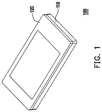
FIG. 1 is a schematic of the electrical wiring device in accordance with a first embodiment of the present invention;
FIG. 2 is an exploded view of the device shown in FIG. 1;
FIG. 3 is a perspective view of the device shown in FIG. 1 without the cover assembly or back body;
FIG. 4 is a perspective view of the shutter assembly optionally employed in conjunction with the present invention;
FIG. 5 is a perspective view of the device shown in FIG. 1 without the center night light lens;
FIG. 6 is a perspective view of the fully assembled device shown in FIG. 1;
FIG. 7 is a schematic of the electrical wiring device in accordance with a second embodiment of the present invention;
FIG. 8 is a schematic of the center night light assembly in accordance with the second embodiment of the present invention;
FIG. 9 is an exploded view of the device shown in FIG. 7;
FIG. 10 is a schematic of the electrical wiring device in accordance with a third embodiment of the present invention;
FIG. 11 is an exploded view of the device shown in FIG. 11;
FIG. 12 is a perspective view of the center night light assembly in accordance with the third embodiment of the present invention;
FIG. 13 is a schematic of the center night light assembly in accordance with the third embodiment of the present invention;
FIG. 14 is a schematic of an alternate center night light circuit in accordance with the present invention;
FIG. 15 is a schematic of yet another alternate center night light assembly in accordance with the present invention; and
FIG. 16 is a perspective view of the fully assembled device in accordance with the third embodiment of the present invention.
Detailed description
Reference will now be made in detail to the present exemplary embodiments of the invention, examples of which are illustrated in the accompanying drawings. Wherever possible, the same reference numbers will be used throughout the drawings to refer to the same or like parts. An exemplary embodiment of the electrical wiring device of the present invention is shown in FIG. 2, and is designated generally throughout by reference numeral 10.
As embodied herein, and depicted in FIG. 1, a schematic 100 of an electrical wiring device 10 in accordance with an embodiment of the present invention is disclosed. In this example, the schematic shows a protective device that includes ground fault interrupter circuitry. Device 10 includes line terminals (2, 4), load terminals (6, 8), and receptacle terminals (300, 320). Again, the load terminals 6, 8 may also be referred to herein as feed-through terminals. As noted above, these terminals may be connected to wiring configured to provide power to downstream receptacles or switches. Receptacle load terminals 300, 320 are configured to mate with an electrical plug to provide power to an appliance or other such user attachable loads. The line terminals 2, 4 are electrically connected to both load terminals 6, 8 and receptacle terminals 300, 320 when device 10 is reset. When in the tripped state, the circuit interrupter 120 disconnects the load terminals from the line terminals. In addition, the circuit interrupter may disconnect at least one feed-through terminal from a corresponding receptacle terminal.
The ground fault circuitry includes a differential transformer 102 which is configured to sense load-side ground faults. Transformer 104 is configured as a grounded neutral transmitter and is employed to sense grounded-neutral fault conditions. Both differential transformer 102 and grounded-neutral transformer 104 are coupled to detector circuit 106. Power supply 112 provides power for GFI detector circuit 106. Note that in this embodiment, the lighting assembly 200 is disposed in series with power supply 112. The light assembly 200 will be described in greater detail below. Referring back to the operation of the detection circuit, detector 106 provides an output signal on output pin 7 based on the transformer outputs. The detector output signal is filtered by circuit 108. Filter circuit 108 filters out noise to thereby substantially reduce the possibility of false tripping. The filtered output signal is provided to the control input of SCR 110. When SCR 110 is turned ON, solenoid 116 is energized. Solenoid 116 actuates the trip mechanism to thereby trip circuit interrupter 120. The trip solenoid 116 is energized until the circuit interrupter trips to remove the fault condition. Accordingly, there is no signal at output pin 7 and SCR 110 is turned OFF. The time that the solenoid remains energized is less than about 25 milliseconds. After the fault condition has been eliminated, circuit interrupter 120 may be reset by way of reset button 260.
Although FIG. 1 has disclosed a ground fault circuit interrupter circuit, those of ordinary skill in the art will understand that the present invention should not be construed as being limited to GFCIs. The present invention is suitable for use in other types of protective devices such as AFCIs. For example, the sensor in an AFCI is similar to transformer 102 but is typically configured to sense load current by way of a toroidal transformer or a shunt and/or line voltage by way of a voltage divider. The detector in an AFCI is similar to detector 106 but is configured to detect an arc fault condition on the basis of frequency spectra or high frequency noise bursts. Once an arc fault condition is detected, a signal is sent in a similar manner to an SCR which in turn activates a trip mechanism to trip the circuit interrupter. The TVSS (SPD) is another example of a protective device. During a lightning storm, the TVSS (SPD) limits the voltages in the distribution system to a safe level. The TVSS includes a voltage surge suppressing structure between hot and neutral terminals such as spark gap 130. Surge suppressing devices may be disposed between hot and ground terminals or between neutral and ground terminals. The surge suppressing device(s) are selected from a family of devices that includes spark gaps, MOVs, varistors, capacitors, avalanche and devices. More than one surge suppressing component may be disposed between a pair of terminals. Thus the spirit of the invention disclosed herein applies to GFCIs and to protective devices in general.
The present invention addresses certain end of life conditions by denying power when the device is unable to function. One end of life condition may cause the solenoid to remain energized when a fault condition is not present or when the circuit interrupter is in a tripped state. The solenoid is susceptible to burn-out when SCR 110 is permanently ON. This typically happens when SCR 110 is permanently shorted out. Most solenoids are configured to be energized only momentarily. They tend to burn out if energized for more than about 1 second. Once the solenoid burns out, the circuit interrupter is incapable of being tripped. As a result, the load terminals are permanently connected to the line terminals even when there is a fault condition.
In this embodiment, solenoid burn-out is prevented by an auxiliary switch 114. Auxiliary switch 114 is configured to open when circuit interrupter 120 is in the tripped position. If SCR 110 is shorted, or is permanently ON, auxiliary switch 114 ensures that solenoid 116 is not permanently connected to a current source. Accordingly, if reset button 260 is activated, circuit interrupter 120 resets but immediately trips in response to the trip mechanism, which in turn moves auxiliary switch 114 to the open position before solenoid 116 is able to burn out.
The auxiliary switch 114 provides other benefits. Those of ordinary skill in the art will understand that a metal oxide varistor (MOV) is frequently employed in protective devices to protect the electrical circuit from voltage surges that sometimes occur in the electrical distribution system. The end-of-life failure mode of a MOV is typically an electrical short. The resulting current can be enough to thermally damage the enclosure of the protective device. In one embodiment of the present invention, MOV 118 is connected in series with auxiliary switch 114 and trip solenoid 116 to eliminate most over-current situations. Thus, when MOV 118 reaches end of life and shorts out, trip solenoid 116 is energized to open auxiliary switch 114 and the flow of short circuit current is terminated before any damage ensues.
As noted above, the light assembly 200 is disposed in series with power supply 112. The schematic shows that the light assembly 200 includes at least two light emitting diodes 202. As such, light emitting diodes 202 are energized when the circuit interrupter 120 is reset and deenergized when the device is tripped. Thus, the light assembly 200 functions as a reset indicator in this embodiment.
Referring to FIG. 2, an exploded view of the device 10 embodying the schematic provided in FIG. 1 is shown. The device housing includes a back body 12 and separator member 14. The electromechanical components forming GFCI 100 are disposed therebetween. The GFCI 100 is inserted into back body 12 such that the line terminals (2, 4) and the load terminals (6, 8) are accessible to the installer. The spark gap structure 130 is disposed between the line terminals (2, 4). The separator is a molded member configured to accommodate both the various GFCI structures disposed underneath it as well as the receptacle terminal structures (30, 32) disposed above.
The neutral receptacle terminal structure 30 includes neutral face receptacle terminals 300 and a fixed contact 302. The terminal structure 30 is disposed in alignment slots formed in the separator 14 such that fixed contact 302 extends through separator 14 in alignment with the cantilevered line and load contacts in GFCI 100. The cantilevered structure is shown in greater detail in FIG. 3. The hot receptacle structure 32 is the mirror image of the neutral receptacle structure, and therefore, includes hot face receptacle terminals 320 and hot fixed contact 322. The ground strap 16 is also mounted within separator 14. The ground strap 16 includes an offset feature 162. The amount of offset roughly corresponds to the thickness of the tamper-resistant shutter mechanism 18. The offset 162 accommodates the thickness of the shutter mechanism 18 such that the front surface of the cover assembly 20 is flush with the wall plate after the device 10 is installed.
In this embodiment, LEDs 202 are connected to the printed circuit board 101 via pigtail wires (not shown for clarity of illustration) that extend through the separator 14. The LEDs 202 are inserted into a reflector portion 204 formed within the front cover assembly. Reflector 204 is described in greater detail below.
The cover assembly 20 includes face receptacle openings 22 disposed at either end thereof. A test button opening 24, reset button opening 26, and night light opening 208 are disposed in the surface area between the receptacle openings 22. Obviously, the test button opening 24 accommodates the test button 240 and the reset opening 26 accommodates the reset button 260. The night light opening 208 extends across substantially the entire width of mesa 21, which is the raised portion of the cover member 20. The night light is configured to accommodate lens element 206. Of course, the reflector member 204 is coupled to the underside of the cover 20 within opening 208.
The reset button 260 includes a stem portion 262 and coil spring 264 that extend through strap 16 and into the latch block disposed in GFCI 100. Therefore, the reset button is disposed on the central longitudinal axis of the device alongside the night light opening 208. The test button 240 is disposed alongside the reset button 260 on one side of the central latitudinal axis opposite the night light opening 208, which is disposed on the other side of the axis The major axis of the user accessible surfaces of the test and reset buttons are substantially normal to each other.
Turning now to the structure of the lighting assembly 200, in one embodiment, the reflector is a molded portion of the front cover. Of course, those of ordinary skill in the art will understand that the reflector 204 may be formed separately and snapped into place within opening 208 of front cover 20. The interior surface of the reflector 204 may be imbued with its reflective quality using any suitable method. For example, the surface may be formed using a relatively shiny white plastic material that is naturally reflective. The surface may be polished like a mirror. A reflective surface may be disposed over a plastic surface by painting or plating techniques known to those of ordinary skill in the art. Of course, separator 14 includes apertures disposed therein (not shown) that accommodate the LEDs 202. Those of ordinary skill in the art will understand that there may be one or more LEDs 202 employed within the scope of the present invention. In one embodiment, the LEDs are implemented using white LEDs that have a minimum 100.degree. viewing angle. The amount of light emitted by each LED on its optical axis is greater than about 500 MCD (millicandelas). The reflector and lens are configured so that the intensity of the light emitted by LEDs 202 into a region of space surrounding device 10 is greater than about 20 millifootcandles. In another embodiment, the intensity of the emitted light is greater than about 50 millifootcandles.
Lens 206 is substantially flush with the front surface of the cover member 20. As noted previously, lens 206 extends across the full width of the front cover member 20. In one embodiment, the surface area of lens 206 measures 0.300 inches by 1.160 inches. Lens 206 is approximately 0.14 inches thick. If the separator is molded into the front cover 20, lens 206 snaps into opening 208 from the top. In an alternate embodiment (see FIG. 9), lens 206 has a "U-shaped" cross-section, having the same cross-sectional profile as "mesa" 21 formed in front cover 20. Lens 206 wraps around mesa 21 when it is inserted from above. Lens 206 may have lenticular lens elements formed on the interior surface disposed adjacent to the LEDs 202. As those of ordinary skill in the art will understand, lenticular lens elements diffuse incident light to thereby provide uniform illumination.
In yet another embodiment of the present invention, the combination of the LEDs 202, plug tail wires, separator 204, and lens 206 may be installed as a single unit that is snapped into the front cover.
Referring to FIG. 3, a perspective view of the GFCI 100 portion of device 10 is shown with the back body 12, separator 14, and cover member 20 not shown. Of particular note is the position of the receptacle terminal structures (30, 32) with respect to the line and load cantilevers. Neutral line terminal 4 includes a line terminal which extends into the interior of the GFCI device. The neutral line cantilever includes contact 122 disposed at the end thereof. Neutral load terminal 8 also includes a cantilever having dual contact 126 at the end thereof. Contacts 122 and 126 are vertically aligned with fixed contact 302. Only hot fixed contact 322 may be seen on the "hot side of the circuit interrupting structure. However, those of ordinary skill in the art will understand that the hot interrupting contacts (124, 128 322) and the neutral interrupting contacts (122, 126, 302) form the four-pole circuit interrupter 120 that is shown schematically in FIG. 1. The LEDs 202 (lighting assembly 200) appear to be suspended in space in FIG. 3. In actuality, the LEDs 202 are connected to printed circuit board 101 via pig tail wires that are not shown in this view for clarity of illustration.
As embodied herein and depicted in FIG. 4, a perspective view of the shutter assembly optionally employed in the first embodiment of the present invention is shown. Reference is made to U.S. patent application Ser. Nos. 10/729,685, 10/900,778, and 11/609,793, which are incorporated herein by reference as though fully set forth in its entirety, for a more detailed explanation of various embodiments of the protective shutter assembly 18. The shutter assembly may be optionally employed in any of the embodiments disclosed herein.
When assembled, the upper shutter 190 is inserted into lower shutter 170 until stop members 1920 extend beyond rail guides 1782 and snap into place. This position represents the closed position, wherein the upper transverse structure 196 covers neutral aperture 174 (not shown) and upper base 198 covers hot aperture 176 (not shown). The lower shutter member 170 and the upper shutter member 190 are movable relative to each other from the closed position to the open position in response to being simultaneously engaged by the hot plug blade and the neutral plug blade of an electrical plug. To facilitate this movement, shutter members (170,190) are made from a family of plastics having natural lubricity. These include nylon 6-6, Delrin, and Teflon. Shutter members (170,190) may be made from a substrate on which these materials are coated, the substrate having a differing flammability or flexural characteristic.
If a foreign object having a width substantially the same as a hot plug blade is inserted into the hot receptacle opening, the shutter assembly remains closed. The foreign object causes ramp 1784, and therefore, lower shutter 170, to move. However, this foreign object insertion does not cause upper shutter 190 to move relative to shutter 170. As a result, the foreign object inserted into the hot receptacle opening strikes base member 198 of the upper shutter. On the other hand, if a foreign object having a width substantially the same as a neutral plug blade is inserted into the neutral receptacle opening, transverse structure 196 will move upper shutter 190 but not move lower shutter 170. Accordingly, the lower base member 173 does not move and the neutral aperture 174 (not shown) is not exposed. Thus, the foreign object inserted into the neutral receptacle opening strikes lower base member 173.
Only when the hot plug blade and the neutral plug blade of an electrical plug simultaneously engage ramp 1784 and ramp 1962, respectively, will the lower shutter member 170 and the upper shutter member 190 move relative to each other from the closed position to the open position. In the open position, the lower hot aperture 176 is aligned with the upper hot contact aperture 194 and, the inward edge of the lower neutral contact aperture 174 is substantially aligned with the outer edge of ramp 1962. In this position, the lower shutter 170 and the upper shutter 190 allow the plug contact blades to pass through the protective shutter 18 and engage the receptacle terminals disposed in the interior of the electrical wiring device. On the other hand, a foreign object such as a hairpin is likely to slide off of either side of ramp 1784 or ramp 1962. Obviously, if the foreign object has slid off the ramp, force cannot be applied to the object to open the corresponding shutter.
In another embodiment, the predetermined electrical plug geometry that opens the shutters may include only some of the characteristics that have been described. The geometry may include just one or more of the following: two plug blades separated by a predetermined distance, plug blades contacting the two blade structures simultaneously, a neutral plug blade having a predetermined width, or a hot plug blade having a predetermined width. Plug blade width will not matter if ramps 284 and/or 462 approach the widths of their respective contact structures.
In another embodiment, shutters (170, 190) open in response to the insertion of two objects without particular heed given to their geometries. This may be accomplished by extending the widths of ramp 1784 and ramp 1962 so that regardless of the sizes of the objects, there is nowhere for either or both objects escaping the ramps as they are inserted into the device. As such, it is assured that the two shutters will open.
The movement of the upper shutter 190 and the lower shutter 170 is effected by spring member 180. The spring member 180 is configured to bias the frameless shutter sub-assembly, i.e., lower shutter 170 and upper shutter 190, in the closed position. Spring member 180 is compressed further in the open position and, therefore, opposes movement of the frameless shutter sub-assembly from the closed position to the open position. Accordingly when the electrical plug is removed, the spring moves the frameless shutter sub-assembly from the open position to the closed position. Stated differently, only a single spring is necessary to effect the closed position of the shutter assembly.
As alluded to above, the protective shutter assembly 18 includes a spring retainer mechanism. The spring retainer mechanism includes lower shutter retainer pocket 1780 and upper shutter retainer pocket 1960. The spring retainer mechanism is configured to retain the spring member 180 within the frameless shutter sub-assembly and substantially prevent the spring member from being separated from the frameless shutter sub-assembly. As those of ordinary skill in the art will appreciate, the protective shutter assembly 18 may be dropped and/or exposed to vibrational and/or mechanical forces during automated assembly. As shown in FIG. 4, retainer pockets (1780, 1960) are equipped with retainer lips that prevent the spring member from being jarred loose.
Referring to FIG. 5, a perspective view of device 10 without the center night light lens 206 is shown. This view clearly shows reflector member 204 disposed within the front cover member 20. In the embodiment shown, two LEDs 202 are disposed within the reflector member 204. The "bathtub" shape of the interior surface of the reflector is configured to redirect light emitted from the side portions of LEDs 202 out from opening 208. As noted above, the reset button 260 and test button 240 are disposed adjacent to the light assembly 200 in the manner previously described. FIG. 6 is a perspective view of the fully assembled device with lens element 206 in place. The lens element is substantially flush with respect to the front surface of cover member 20. Again, any of the shutter assemblies disclosed in U.S. patent application Ser. Nos. 10/729,685, 10/900,778, and 11/609,793 may be employed herein since these applications are incorporated by reference as though fully set forth in its entirety. As depicted in FIG. 6, the shutter assembly 18 is disposed within or under the front cover assembly 20 and prevents access to electrical power unless the hot and neutral blades of the plug blade set are simultaneously inserted into the receptacle openings. Stated differently, the shutter 18 will not open when an object is inserted into either the hot receptacle opening or the neutral receptacle opening. In reference to FIGS. 5-7 and 21 of U.S. patent application Ser. No. 11/609,793, the front cover member 50 or the front cover member 2150 in conjunction with a separator member 2110 are used in conjunction with the shutter assembly to prevent a foreign object or probe from being inserted at an angle in an attempt to by-pass the shutter. FIG. 5 of U.S. patent application Ser. No. 11/609,793 shows a registration feature 56 that includes a groove 560 that is configured to accept the snaps 220 (FIG. 3) such that the shutter assembly is fixed in position. This feature causes foreign objects to slide off the ramps and into the side registration wall 56 or an end wall, but not gain access to the region under the shutter 18. FIG. 21 of U.S. patent application Ser. No. 11/609,793 shows an electrical device 2100 that includes a front cover 2150 and a separator 2110. If, for example, a foreign probe (e.g., a screw driver tip) is directed into receptacle opening 2154 at an acute angle in an attempt to by-pass the shutter assembly, it will strike the separator end wall 2120 and/or the floor portion normal thereto, but in no event will it be able to enter the separator blade opening 2124 unless the shutter assembly is completely removed. Stated differently, the front cover and the separator include stop members proximate to the shutter ramps that prevent the shutter from being by-passed by a foreign object or probe.
The description continues in the full USPTO document.
 Lapsed, fee not paid7 drawings