Cross-reference to related patent applications
This application is an application claiming the benefit under 35 USC 119(e) U.S. Application 60/562,157, filed Apr. 14, 2004, incorporated herein by reference in its entirety.
Field of the invention
The present invention relates to improved electrochemical devices, such as batteries, capacitors, fuel cells, sensors or the like. More specifically this invention relates to improved housings for electrochemical devices that provide high specific power and energy outputs per weight and volume of the device.
Background of the invention
With the increasing pace of advances in electronics there has been a corresponding increase in the need for electrochemical devices that safely and efficiently provide sufficient energy density to power advanced electronic devices, especially portable electronic devices, while still being economically viable. Older battery configurations are often unsuitable to meet these increased demands. Out of environmental and efficiency concerns, the reach of electricity providing devices has been expanded to new areas including hybrid electric vehicles. Ideally, an electrochemical device will provide high current density, decrease the internal resistance of the battery, and effectively manage the thermal output of the electrochemical device to increase the longevity of the device. These features can be achieved by providing massive and/or large surface-area connections between electrodes and cell current collectors, and specifically between cells in a battery.
A second important feature of the high power device is internal heat removal. Thermal management is important to the long life of Li-ion batteries in retaining battery capacity particularly due to electrolyte degradation. High power to external circuitry generally generates a like amount of energy as heat over a short time duration and internal to the cell. Excessive temperatures will destroy (e.g. melt the microporous polymer separator or autoignite the flammable organic electrolyte) or significantly shorten the useful life of the Li-ion cell. Under high pulse power, heat is generated at the electrode/separator interface due to limited ionic conduction. For the conventional jelly-rolled cell, the most direct path for heat loss is across the layers of heat sensitive microporous polymer. Excessive temperature within the cell will locally shutdown the microporous polymer resulting in still higher temperatures possibly leading to the auto-ignition of the organic electrolyte.
An electrochemical device comprised of cathode and anode electrodes physically exposed to an electrolyte can generically be used to convert between chemical and electrical energies. A housing can enclose these electrode and electrolyte components, and can even seal them from the atmosphere. Batteries, fuel cells, and capacitors are but a few such specific electrochemical devices to which this invention relates.
As the electrical power in terms of voltage and/or amperage of each pair of cathode and anode electrodes (or cell) is generally small, many separate pairs of cathode and anode electrodes or cells can be used in a single housing. Current collectors are generally used to electrically interconnect the cells, in parallel and/or in series, to provide usable voltage and amperage outputs at exposed terminals on the electrochemical device.
The electrochemical device performs usable work when ions pass between the electrodes of each cell via the electrolyte, and when electrons concurrently pass through each cell via the electrodes. The generated voltage per cell is predetermined by the electrochemical reaction of the component materials used, and the generated amperage and/or power available is dependent on the configurations and masses of these active components.
The specific output energy of the device can be provided in terms of watts-hours per device weight, and the specific output power of the device can be provided in terms of watts per device weight. Output values of existing electrochemical devices are typically small fractions of theoretically possible output values because of internal resistances and other inefficiencies (hardware mass and volume).
The resistance to ion conduction between the electrode elements is one major source for internal power loss. Such resistance, R, can be theoretically determined with the expression R=.rho.I/A. where: ".rho." (rho) is the impedance value of the electrolyte; "1" is the thickness of the electrolyte; and "A" is the interfacial contact area between the electrode elements and electrolyte.
The ionic-impedance value, .rho., is not easily subject to modification and is not effective as a design parameter. Designers of electrochemical devices thus strive to reduce the electrolyte thickness "I", and to increase the interfacial contact area "A" between the electrode elements and the electrolyte.
Different configurations of the cathode and anode electrodes, of electrolyte separation, and of current collection have been proposed. For example, a cathode electrode band can be zig-zagged to define separate compartments for holding the electrolyte, and inserted with elongated rod-like anode electrodes into the electrolyte spaced from the cathode electrode. The interfacial contact area "A" effectively is less than the overall surface area of the anode rods, as some rods oppose one another rather than the cathode.
Also, a zig-zagged, folded separator band can define opposing compartments for holding and isolating plate-like cathode and anode electrodes, with electrolyte engulfing all of these components. In an alternative design, each cell can be formed with C-shaped electrodes and a Z-shaped separator sandwiched therebetween. Alternatively, a separator band having electrically conductive surfaces can be folded and sandwiched between separate sets of respective plate-like cathode and anode electrodes placed between the separate oppositely facing folds. A "jellyroll" cell can be formed by coiling a preformed assembly of cathode and anode electrodes and a separator on itself to yield a cylindrically shaped electrochemical device, wherein the face-to-face electrodes and sandwiched electrolyte and separator structures increase the interfacial contact area "A" between the electrodes. However, the very breadth of the facing electrodes and sandwiched electrolyte and separator raise another issue, namely the sufficiency of the structure in maintaining and in supporting the electrode elements physically separate during assembly and during operation. This includes withstanding thermal expansion and contraction forces of the cell components during operational temperature changes. Increasing the thickness of the sandwiched electrolyte and separator to provide needed strength and/or durability also increases the ion-conducting electrolyte thickness "I", offsetting benefits obtained by increased interfacial contact area "A".
Current collectors used in these cell arrangements add significant weight, and thus reduced specific cell energy and power outputs. For example, isolated conductors are generally connected to the electrodes and routed along extended paths independently of the electrodes to the external terminals. These conductors should carry the full cell current, and thus should be of sufficient mass and cross-section to keep internal resistance manageably low. For a typical battery design of connected terminals, electrode tab/current collector/cell terminal resistance/battery terminal resistance can account for a 50% reduction in battery power output from theoretical capability. Generally, massive connectors are used to avoid power loss for high powered batteries.
Additionally, these cell arrangements provide electrodes of limited size and/or thickness, limiting the quantities of usable electrode materials, and thus, limiting maximum cell storage energy and/or operating cycle-life, particularly for rechargeable cells.
The dilemma of these designs is that power gains obtained by increasing the interfacial electrode area "A" across the electrolyte generally are typically offset by increased electrolyte thickness "I" and that the weight and volume of the current collectors reduce specific energy and power outputs. Power can be increased, but only at the expense of reduced energy storage capacity per weight and volume and at increased cost due to needed additional hardware. High interfacial area "A" of the spirally wound "jellyroll" configuration merely trades off usable power against the energy density because a minimum separator thickness is needed for cell durability and cycle-life. Existing bipolar cell arrangements do not escape this power and energy trade off dilemma; nor do fuel cell electrochemical devices.
The rolled-ribbon cell technology disclosed in U.S. Pat. No. 5,219,673 has made great strides towards achieving enhanced power density for electrochemical devices. Specifically applied to Li/organic-based electrolyte chemistries, improved batteries are formed using stackable disk-shaped cells to realize near optimum power capability from the cells. Further objectives of batteries for high-pulse power requirements, such as for hybrid electric vehicles and for power tools, are to continue to reduce battery cost and to increase durability. These Li/organic-based electrolyte battery chemistries, although exhibiting quite high voltages (3-5 volts), have relatively low current density capabilities. One limiting factor is the attempted use of relatively-thin components, i.e. the electrode and separator layers. A practical device generally, requires a lot of active area. For example, with peak current density of 10 mA/cm.sup.2, it can require 1000 cm.sup.2 active area to achieve 10 A. For hybrid electric vehicles, the current is on the order of 100 A at 200-400 volts (equivalent to 20-40 kW).
Thus, a further dilemma is the large number of small cells that form such batteries. Internal heat generation resulting from the large numbers of small cells (e.g. 1 Ampere-hour (Ah) capacity uses 18,650 cells) is a major power loss source. More recently, larger cells (10 Ah) have used a prismatic configuration. These cells have broad electrodes with multiple tabs connected to a traditional terminal connection. These prismatic cells are hard-wired together (terminal-to-terminal) in a rectangular box. Nonetheless, this arrangement of substantially larger cells can still sacrifice 50% of the theoretical power of the cell chemistry. Thus, there is a continuing and persistent need for electrochemical devices which have high energy density, provide high power output, and approach the theoretical limit for electrical power output.
A Li/organic-based electrolyte battery for high power applications, such as for hybrid electric vehicles, should also incorporate features to enhance safety and battery longevity. Because there is internal gas pressure generated during battery operation and during battery degradation conditions, there needs to be non-catastrophic, cost effective means to relieve the gas pressure. The typical means is to include a rupture disc on the housing of the Li-ion cell. Rupture of a disc housing causes irreversible failure of that battery, and, if a disc ruptures, electrolyte may escape to further degrade the battery. Additionally, because the electrolyte batteries often operate in environments that cause both shock to and vibration of the battery, the battery should be durable.
Summary of the invention
An embodiment of the present invention provides a housing for an electrochemical device comprising a first cup, a second cup, a fastener, and a gasket. The first cup may include a first plate having a circumferential edge and a first wall, the first wall extending from the first plate along the circumferential edge. The second cup may include a second plate having a circumferential edge and a second wall, the second wall extending from the second plate along the circumferential edge, wherein the first cup fits together with the second cup thereby creating an enclosure. The fastener may include a threaded stem made of conducting material and extending from the center of the first plate in the same general direction as the first wall and a hollow tube made of insulating material and extending from the center of the second plate in the same general direction as the second wall, wherein the threaded stem fits inside the hollow tube and assists in holding the second cup together with the first cup. The gasket may be made of plastic material that fits over the first wall wherein the gasket electrically isolates the first cup from the second cup and seals the enclosure from the ambient atmosphere surrounding the housing.
Certain embodiments of the present invention are found in the following paragraphs:
The present invention provides a housing for an electrochemical device comprising a first cup, the first cup comprising a first plate having a circumferential edge; and a first wall, the first wall extending from the first plate along the circumferential edge; a second cup, the second cup comprising a second plate having a circumferential edge; and a second wall, the second wall extending from the second plate along the circumferential edge, wherein the first cup and the second cup are capable of fitting together thereby creating an enclosure; and a fastener, wherein the fastener attaches the first cup to the second cup.
In one embodiment of the previously described housing, the fastener comprises one or more stems; and one or more tubes, wherein the one or more stems fit inside one or more of the one or more tubes.
Also provided is the fastener of the previous paragraph, wherein one or more of the one or more tubes and the one or more stems at least partially comprises an insulating material.
The present invention also provides the fastener of the previous paragraph, wherein the insulating material comprises a plastic material.
Also provided is the fastener as previously described, wherein one or more of the one or more tubes and the one or more stems at least partially comprises a conducting material.
Further provided is the fastener of the previous paragraph, wherein the conducting material comprises a metal.
Also provided is a fastener in which one or more of the one or more stems and the one or more tubes is threaded.
In another embodiment of the housing as previously described, the fastener comprises a grommet; and a tube, wherein the tube fits inside the grommet and is attached thereto.
The invention also provides a fastener in which one or more of the grommet and the tube is at least partially comprised of an insulating material.
Further provided is a fastener of the previous paragraph, wherein the insulating material comprises a plastic material.
The invention also provides a fastener as described in the alternate embodiment in which one or more of the grommet and the tube is at least partially comprised of a conducting material.
Also provided is the fastener of the previous paragraph, wherein the conducting material comprises a metal.
The invention further provides the alternate embodiment of the fastener wherein the tube is hollow and includes a side channel to an interior of the electrochemical device, thereby allowing gases to escape.
The invention also provides an embodiment of the fastener in which one or more of the tube and the grommet is threaded.
In yet another embodiment, the housing further comprises a gasket wherein the gasket electrically isolates the upper cup from the lower cup.
Also provided is a gasket comprised of a plastic material.
Further provided is a gasket that fits over one or more of the wall of the first cup and the wall of the second cup.
The present invention also provides an embodiment of the housing in which the first cup and the second cup comprise the same material.
The present invention also provides a housing further comprising an electrode assembly comprising: a positive electrode layer wherein the positive electrode layer is electrically coupled to one of the first cup and the second cup; a negative electrode layer wherein the negative electrode layer is electrically coupled to the other of the first cup or the second cup; and a separation layer, wherein the positive electrode layer, the separation layer, and the negative electrode layer are wound around a central axis forming a coil of alternating electrode and separation layers such that the separation layer prevents direct contact between the positive electrode layer and the negative electrode layer; and an electrolyte adjacent to the electrode assembly and enclosed within the enclosure.
Other principal features and advantages of the invention will become apparent to those skilled in the art upon review of the following drawings, the detailed description, and the appended claims.
Brief description of the drawings
The exemplary embodiments will hereafter be described with reference to the accompanying drawings, wherein like numerals will denote like elements.
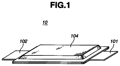
FIG. 1 is a cut-away perspective view of the electrode/separation layer configuration in the electrode assembly in accordance with an exemplary embodiment.
FIG. 2 is a right side facial view showing the electrode assembly of FIG. 1 coiled on itself to define a rolled-ribbon cell (laminate cell membrane) of the type suited for forming an electrochemical device in accordance with an exemplary embodiment.
FIG. 3 depicts the process for making the electrode/separator assembly in accordance with an exemplary embodiment.
FIG. 4 is a cross-sectional view of the cell preassembly taken along line 4-4 of the process of FIG. 3.
FIG. 5 is a cross-sectional view of the cell preassembly taken along line 5-5 of the process of FIG. 3.
FIG. 6 is a cross-sectional view of the cell preassembly taken along line 6-6 of the process of FIG. 3.
FIG. 7A depicts the housing for the electrochemical device in accordance with an exemplary embodiment; FIG. 7B depicts a cross-sectional view of the peripheral seal area of the housing for the electrochemical device including the `U` shaped polymeric gasket; FIG. 7C depicts the outer pan of the housing for the electrochemical device including the center fastener, polymeric tube; FIG. 7D depicts a cross-sectional view of the housing for the electrochemical device including the `U` shaped polymeric gasket and the threaded stem and plastic tube fastener.
FIG. 8 depicts a radial view of the housing for the electrochemical device including a fastener in accordance with an exemplary embodiment.
FIG. 9A depicts a radial view of the plastic tube portion of the fastener for the housing of the electrochemical device; FIG. 9B depicts a cross-sectional view of a washer for attaching the fastener in accordance with an exemplary embodiment; FIG. 9C depicts a cross sectional view of the plastic tube portion.
FIG. 10A depicts a cross sectional view of the housing for the electrochemical device showing a fastener including a plastic tube and grommet; FIG. 10B depicts a cross sectional view of the housing for the electrochemical device showing a fastener including a plastic tube and grommet along with a detailed cross sectional view of the fastener and a cut away radial view of the housing with the fastener; FIG. 10C depicts a pictorial cross sectional view of the housing for the electrochemical device showing a fastener including a plastic tube and grommet along with a detailed cross sectional view of the fastener.
FIG. 11 is a radial edge section of a bipolar electrochemical device incorporating the electrode assembly in accordance with an exemplary embodiment.
FIG. 12A shows a high voltage battery made up by stacking disc-shaped electrochemical cells in accordance with an exemplary embodiment; FIG. 12B shows an end cross-sectional view; FIG. 12C shows a detailed cross-sectional view of the high voltage battery, taken along line 12-12.
FIG. 13A depicts an embodiment that can achieve greater cooling of the electrochemical cells; FIG. 13B shows a cross-sectional view of a battery housing with cooling jacket.
FIG. 14 depicts a current vs. time profile and voltage vs. time profile for a cell under a compressive load.
FIG. 15 depicts a current vs. time profile and voltage vs. time profile for a cell in accordance with an exemplary embodiment wherein the cell is not under a compressive load.
Detailed description of the invention
Exemplary embodiments described herein provide an improved cell arrangement involving the orientation of positive and negative electrodes (as depicted in the drawings throughout and referred to as e.g. 28p, 22p, etc.), interpositioned separator and/or electrolyte, and current collectors. The improved cell uses an electrode assembly with laminated electrode/foils comprised of alternately arranged, generally parallel, positive and negative electrodes, and a separator layer and/or electrolyte formed of a very thin ionic-conductive ribbon-like layer configured in a tight serpentine manner and physically interposed between the electrodes. This basic laminate cell preassembly is layered on itself, such as by winding or coiling it in a spiral to form an electrode assembly in the general shape of a flat disc (wherein the diameter is preferably greater than twice the thickness of the disk). The cell membrane is sandwiched between plate-like current collectors with the electrode interfaces primarily perpendicular to the current collectors to make up an electrochemical cell.
Because of the expense of lithium ion batteries, which also provide the greatest electrochemical potential and largest energy content, the rolled-ribbon cell configuration has particular utility for cells employing lithium/organic electrolyte cell chemistry, although the present invention is also well suited to other cell chemistries, including, but not limited to, nickel/metal hydride and alkaline electrolyte systems. Of particular interest, the technology provides high pulse power devices at reduced costs and with excellent thermal management producing kW levels of power.
The improved cell arrangement in an exemplary embodiment uses a ribbon-like cell assembly with coated foil electrode strips extending beyond the edge of the folded separator when viewed in cross section. The extended electrode areas can have less or no active electrode material, and the electrode ribbons are preferably cored with metal foils or other electron conducting material e.g. carbon paper and/or electrically conductive polymer. For a 5 inch diameter cell, 100 to 250 ft of electrode edge contact with a cell housing is typically achieved.
The exemplary embodiments provide for adding electrode material or cell capacity by way of extending the electrode strips beyond the separation layer. Instead of having electrode discs applied to the major faces of the rolled-ribbon cell or cell separator membrane, as in earlier button type electrochemical cells, the electrode extensions define reservoirs of electrode material. These extensions are subsequently compacted into a disc as the cell is assembled into the disc housing hardware.
The exemplary embodiments also provide for a separator ribbon configuration in which the folds of the separation layer are oriented up and down at each edge. This arrangement serves to align the electrode ribbons with respect to the separator and helps to ensure the positioning of the electrodes and separator during the cell winding operation. This alignment aids in forming a flat disc cell.
The exemplary embodiments can provide an electronic component that can serve to electrically remove a shorted or defective cell. Preferably the electronic component is embedded within the cell and resides at the center hub of the cell for ease of manufacture, for example by initiating the cell winding. In a preferred embodiment, a diode is utilized for removing (or short-circuiting) the non-operative cell. Similarly, the component can act to bypass current at overcharge or excessive voltage conditions.
The invention also provides a button-type cell housing. The housing comprises two opposing shallow cups, a first cup and a second cup, that are electrically isolated from each other using a polymeric "U" shaped gasket. Each cup comprises an essentially flat surface surrounded by a wall that extends from the flat surface or plate creating a receptacle or enclosure for holding the electrode assembly. The gasket extends along at least a portion of the wall of one of the two opposing cups. The first and second cups fit together, one within the other, to create an enclosure for holding the electrode assembly. The gasket further forms a gas-tight seal for the interior contents of the cell. In an exemplary embodiment, the gasket is insert molded to one of the cups. Forming the gasket with an integral plastic seal such as by using insert molded plastic for the gasket improves the quality of the cell and reduces the cost of assembling the cell.
The cups interface with the perpendicular electrode member of another electrochemical cell to serve as both a current collector and a cell terminal. One cup acts as a positive terminal and the other cup acts as a negative terminal and, together with the electrode assembly, the cups form a cell. The positive electrode substrate can be made of essentially the same material as the surface of the positive terminal, and the negative electrode substrate can be made of essentially the same material as the surface of the negative terminal. In some embodiments, the positive terminal and positive electrode substrate are generally made of aluminum, and the negative terminal and negative electrode substrate are generally made of copper. To increase durability in response to temperature change, the same metal material can be used to form a substrate for both the positive and negative terminals. In an exemplary embodiment, the substrate material can be carbon steel. Thus, in an exemplary embodiment, the positive electrode substrate and positive terminal are made of aluminized carbon steel, and the negative electrode substrate and negative terminal are made of copper plated carbon steel. The present embodiments can use thinner, lighter gauge metals (for example 10-15 mm thick versus 20-30 mm thick) for the cups, which reduces the weight and volume of the electrochemical device. This configuration also reduces the dependency on a flat, stiff cup to ensure that the electrode adequately contacts the appropriate cup surface.
In exemplary embodiments, the housing for the electrode assembly further comprises a fastener that aligns the first and second cups during assembly and maintains electrode contact with the appropriate cup independent of external pressure on the housing, helping to eliminate the possibility of an open circuit state for a cell. In an exemplary embodiment, the fastener comprises two components. The first component can be molded or attached to the plate of one cup, and the second component can be molded or attached to the plate of the opposing cup so that either of the first or second components fits into the other when the first and second cups are pushed together to form a receptacle or enclosure. The joined first and second components of the fastener thereafter resist detachment from each other thereby holding the first and second cups together. In one alternative embodiment, the fastener comprises a stem that fits into a hollow tube. In another alternative embodiment, the fastener comprises a stem that fits into a grommet. In yet another alternative embodiment, the fastener comprises a tube that fits into a grommet. Other fastener components may be used for holding the first and second cups together as in known to those skilled in the art. As will be apparent, the fastener can be comprised of one, two, three, or more separate components as desired. For example, a single hollow tube can attach to stems on the separate cups, some or all of which can be threaded.
In an exemplary embodiment, the fastener components are attached at or near the center of the interior surface of each plate of the cups so that the component extends from the plate in generally the same direction as the wall. Alternatively, the fastener components may be attached at other locations on the interior surface of each plate. In other alternatives, the fastener components may be attached to either the interior or the exterior surface of the cup walls. The fastener components may be attached, molded, or formed with the cup surfaces using various methods known to those skilled in the art.
At least one of the two fastener components is at least partially made of insulating material, such as plastic polyethylene, polypropylene, Dupont Surlyn, so that the cups are held together to create a fixed internal dimension without conducting electricity across the fastener. In an exemplary embodiment, fastener components made of insulating material can be insert molded to the metal surface of the cup as can any seal or gasket that separates the cups. The second fastener component can be made at least partially of either insulating or conducting material. A metal material can be a suitable conducting material for making the second fastener component. Generally, the fastener should be devised such that electric current is not allowed to pass through the fastener. In combination with the gasket, the fastener holds the housing, including the enclosed electrode assembly, together independent of the external pressure on the housing thereby providing consistent contact between the cups and the electrodes. As shown in FIG. 7D, the center fastener is comprised of pressing a threaded metal stem 64 into a plastic tube 68. As a result, the fastener improves cell durability in response to shock and vibration. In exemplary embodiments, the fastener is located at the center hub of each cup, although the position of the fastener is not particularly limited, and the fastener can be located anywhere on the cup, including off-center, on an edge of the cup or the like.
The first cup of a first cell is adjacent to the second cup of a second cell and the adjacent cups have opposite polarities. For example, if the first cup of the first cell is positive, the second cup of the second cell is negative. In exemplary embodiments, the fastener can further act as a diode by shorting the cell and effectively removing the cell from the battery when the voltage level generated by that cell drops below a predefined value, for example, 0 volts. As a result, a non-operative cell is removed from the battery without causing a failure of the entire battery. As shown in FIG. 7D, a diode 69, a two lead electronic component, has one lead attached to metal cup 28n piercing the base of plastic tube 68 and the other lead piercing the metal cup 28p contacting the stem 64 to thus electronically-bridge metal cups 28n and 28p when the two cups enclose the cell.
In exemplary embodiments, the fastener further operates as a fill tube that allows for the electrochemical device to be filled with an electrolyte. By including a radial hole to the inside of the cell, the fill tube can be an integrated vent and electrolyte fill port, although the fill port and vent can be separate features. The fill tube can act as a vent during cell formation by allowing trapped gas to exit from the housing as the cups enclosing the electrode assembly are pushed together to form the cell. The fill tube can also act as a fill port during the electrical charge of the cell by injecting the electrolyte into the housing surrounding the electrodes. FIGS. 10A-10C shows the fastener also operating as a vent and/or fill tube through the radial hole 90 with passage to cell interior.
The exemplary embodiments also provide a high voltage and high capacity battery by stacking a plurality of button-type cells together. The cells are typically connected in series. Control of internal gas pressure and maintenance of contact pressure between the button cell in the stack can further be accomplished with active pressure, such as a Belleville spring washer. The specified limit for internal pressure is handled by release via the peripheral gasket which can reseal after an event.
The exemplary embodiments also provide for an augmentation of passive thermal management of the high power battery by manifolding cooling fluid about the battery stack and between the disc-shaped cells. A thermostated control pumps the fluid to external cooling such as to a radiator or to a small refrigeration unit. The cell hardware cups of the button-type battery enclosures conduct heat from the electrode/separator interface. Further, via flow passages between the faces of the button cells, a more direct removal of heat is achieved.
The exemplary embodiments also provide a method of making the improved cell and its electrochemical devices.
A rolled-ribbon cell configuration according to the present invention can release close to 100% of theoretical power of the Li/organic electrolyte cell chemistry in substantially larger cells of 5-10 Ah capacity with pulse currents of 100-200 A from a single cell. Further, these stackable cells, preferably having 125 cm.sup.2 diameter intercell contact or more, can deliver the power at the battery level from the battery terminals. Moreover, effective use of a given amount of costly lithiated Ni/Co oxide electrode/electrolyte materials can produce a significant cost advantage and advantages in thermal management. The rolled-ribbon cell used inside a stackable disk cell housing will promote longevity of these costly battery materials. Unlike the prismatic, jelly-rolled cells, internally generated heat from the rolled-ribbon cell can be drawn out from the cell via short conduction paths without crossing the heat sensitive microporous polyethylene/polypropylene separator. Accordingly, the present cells can be operated without the need for active thermal management.
The enlarged cut-away perspective view of FIG. 1 illustrates a cell preassembly 10 suited for forming an electrochemical device such as a battery, fuel cell, sensor, or capacitor. The cell preassembly 10 specifically includes alternatively arranged generally parallel positive electrode 12p and negative electrode 12n, and a separator or electrolyte layer 14 interposed therebetween somewhat in the form of a laminate structure. In this disclosure, the terms anode and cathode will also be used for the electrodes, somewhat interchangeably, as well as the terms separator and/or electrolyte. In the illustrated electrochemical battery device, the separator/electrolyte 14 is of an ionic conductive material; the positive and negative electrodes 12p and 12n are of both ionic and electronic conductive materials; and the terminals of the cell are of electronic-conductive material. The actual materials of these components can depend on the type of electrochemical battery. The electrodes are generally metal foils coated with particles of the active electrode material. Examples of suitable electrodes include without limitation, 10 micron Al or Cu metal foils that can facilitate low cell-resistance and heat removal. Due to the configuration of the present cells, i.e. their short path length, other materials can be utilized, such as carbon fiber material which generally has lower conductivity than metal foil. Preferred materials for the cathode are lithiated metal oxides while preferred materials for the anode are carbon and/or graphite.
Both electrodes can consist of high surface area powders that are held in a 8 percent by weight (wt %) PVDF (polyvinylidene fluoride, e.g. Kynar 720 from Elf Atochem, USA) binder matrix. The positive electrode also contains 8 wt % carbon black (e.g. mesocarbon microbeads (MCMB) or C-Black) for electrical conductivity. Both electrodes are applied as a slurry to the metal foils (typically 10 micron thick copper foil for the negative electrode and 25 micron thick aluminum foil for the positive electrode) which after drying adheres as porous layers (50 micron thick each side) held together by PVDF binder and is later infiltrated with the electrolyte. For the Li-ion cell chemistry, there are two major types of cathode material: Lithium Nickel-Cobalt Doped Oxide and Lithium Manganese Oxide Spinel. Both compositions are available from FMC Corp. Lithium Div. Gastonia, N.C. 28054 as Lectro Plus 600 and Lectro Plus 300, respectively. The preferred composition is LiNi.sub.x Co.sub.y M.sub.z O.sub.2 where Nix is 0.6<x<0.8, Coy is 0.1<y<0.3, and M (e.g. Al) z is 0.05<z<0.1. The composition LiMn.sub.2O.sub.4 is where 2 Li:Mn ratio is 1.02-1.06:1.
The separator 14 is typically a microporous polymer film that maintains physical integrity after undergoing the mechanical manipulations to form the cell preassembly 10. Preferably, separator 14 is a polyethylene/polypropylene film known as CELGARD.RTM. 2300 and CELGARD.RTM. 2400 (Celgard LLC, Charlotte, N.C.), polymeric film known as NAFION.RTM. (Dow Chemical Company, St. Louis, Mo.), or polyethylene oxide with lithium bis-trifluoromethanesulfate amide (Sigma-Aldrich, Milwaukee, Wis.). As can be seen in FIG. 1, the positive and negative electrodes 12p and 12n extend beyond the edge of the separator layer 14. Preferably, the electrodes extend beyond the edge of the separator layer 0.1 to 1.0 mm, particularly 0.5 to 1.0 mm, or more. One skilled in the art will readily be able to determine the preferred length that the electrodes should extend beyond the separator layer based on a number of factors including electrode thickness, separator thickness, and the physical properties of the cell.
A cross-section of the cell preassembly 10 shows that the cell preassembly has opposing sides 16p and 16n, and opposing sides 18e and 18n. The negative electrode 12n extends to and along the sides 16n and 18n, the positive electrode 12p extends to and along the cup of the side 16p, and the separator or electrolyte 14 defines the entire side 18e and completes the remainder of the sides 16n, 18n and 16p. The cell preassembly 10, with this cross-section, can be elongated indefinitely.
The cell preassembly and/or cell membrane can be formed by adapting otherwise conventional techniques. The materials for the electrodes or separator/electrolyte can be available in a flexible or pliable form to extrude and to wind as thin ribbons. The component material of the electrodes can also be available as a liquid, or as a powder to be mixed and fluidized with a binder/solvent system that can be extruded or selectively tape cast or painted by stencil where needed. Powders can be very fine (1-10 micron size) and when mixed can make up 60-90% by weight of the mixture with the binder/solvent making up the balance (preferably about 20%). Binders can be selected from a group including polyvinyl alcohol, PVDF (polyvinylidine fluoride polymer), or thermal setting resin, e.g. polyisobutylene that can decompose by depolymerization. A plasticizer, such as butyl benzol thalate, can also be added to allow the material to be mechanically worked (rolled, corrugated, extruded) at low temperatures.
A cell preassembly 10 can be coiled upon itself about a center core 24 to produce successive layers 10a, 10b, and 10c of a rolled-ribbon cell. FIG. 2 is a right side facial view showing the electrode assembly 22 coiled on itself to define a rolled-ribbon cell (laminate cell membrane) of the type suited for forming an electrochemical device according to exemplary embodiments.
The description continues in the full USPTO document.
 Lapsed, fee not paid1 drawing