Lapsed, fee not paid7 drawings
Telecom & Networks · US 8,730,961 B1
System and method for optimizing router lookup
A system and method for reducing the number of cycles used in CAM lookup.
US 8,730,976 B2 · Assignee: Cisco Technology, Inc. · Inventors: Dontu; Sitaram et al.
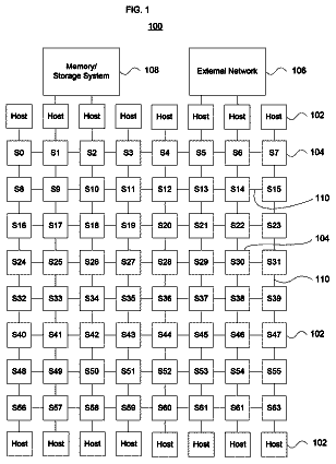
Sheet 1 of 14 from the published document. All sheets in the USPTO PDF
Various methods and systems for preventing erroneous link aggregation due to component relocation are disclosed. Such methods include a method for changing the identifier used by a network device and communicating the identifier change to a peer network device without disrupting an aggregated link. In one embodiment, a method involves detecting an identifier change and sending a Port Aggregation Protocol (PAgP) protocol data unit (PDU) that includes a new identifier and information. The information indicates the identifier change. The new identifier identifies a network device subsequent to the identifier change. Another embodiment of a method involves detecting an identifier change and, subsequent to the identifier change, sending a link aggregation protocol PDU that includes an "old device identifier" field dedicated to conveying an old identifier. The old identifier identifies a network device prior to the identifier change.
Link aggregation is used to logically combine two or more individual links into a single aggregated link. Link aggregation can provide improved performance and increased fault tolerance. Improved performance arises because the aggregated link appears to have a bandwidth equal to the combined bandwidth of the individual links. Traffic can be load-balanced among the individual links. Increased fault tolerance is provided since one or more individual links within an aggregated link can fail without disrupting communication between the devices coupled by the aggregated link. Link aggregation techniques include Link Aggregation Control Protocol (LACP), which is defined in IEEE 803.2ad, and Port Aggregation Protocol (PAgP), which is a standard promulgated by CISCO SYSTEMS, INC. Typically, aggregated links are established between two devices. These devices communicate with each other according
1 of 14 drawing sheets so far from the published document, cropped to the drawing. Every sheet is in the USPTO PDF.
What the patent claimed, word for word. All of it is now free to use.
This invention relates to networking and, more particularly, to link aggregation within a network.
Link aggregation is used to logically combine two or more individual links into a single aggregated link. Link aggregation can provide improved performance and increased fault tolerance. Improved performance arises because the aggregated link appears to have a bandwidth equal to the combined bandwidth of the individual links. Traffic can be load-balanced among the individual links. Increased fault tolerance is provided since one or more individual links within an aggregated link can fail without disrupting communication between the devices coupled by the aggregated link. Link aggregation techniques include Link Aggregation Control Protocol (LACP), which is defined in IEEE 803.2ad, and Port Aggregation Protocol (PAgP), which is a standard promulgated by CISCO SYSTEMS, INC.
Typically, aggregated links are established between two devices. These devices communicate with each other according to a link aggregation protocol in order to determine whether any of the links between the two devices can be operated as an aggregated link. Typically, communication according to the link aggregation protocol takes place using Protocol Data Units (PDUs). Each device includes an identifier, which uniquely identifies that device for purposes of the link aggregation protocol, in PDUs sent by that device. If a device receives PDUs on two different links, and each of the received PDUs includes the same identifier, the device determines that both links are connected to the same partner device. Accordingly, the device can operate those two links as an aggregated link with the partner device.
In order to provide improved network fault-tolerance, field-replaceable components (i.e., components that can be replaced while the equipment is in the field) are often used within networks. For example, network devices can be implemented with multiple field-replaceable line cards. If one field-replaceable line card fails, that line card can be replaced without having to replace the entire network device. Similarly, in a stackable switch, several switches can be interconnected such that the switches act as a single device. If one switch fails, that switch can be replaced without having to replace the other switches within the stackable switch.
When link aggregation is used with devices that include multiple field-replaceable components and it is desired that links going to different field-replaceable components be able to form aggregated links with each other, all of the field-replaceable components that make up the same device must use the same identifier in aggregation protocol PDUs. Otherwise, a partner device would think that each field-replaceable component was a separate network device, and aggregated links would not be formed for links coupled to different field-replaceable components. Typically, one of the field-replaceable components supplies the identifier to all of the other field-replaceable components.
This above arrangement works well, unless the field-replaceable component supplying the identifier is replaced (e.g., due to a failure within that component). At that point, the remaining field-replaceable components within the device continue to use the identifier supplied by the failed field-replaceable component. If the failed field-replaceable component is repaired and replaced in a different part of the network (and thus is no longer part of the device using the identifier), two different devices, the device that used to include the field-replaceable component, and the field-replaceable component, may inadvertently include the same identifier in link aggregation PDUs. If both devices are coupled to the same partner device, an aggregated link can be formed on links coupled to both devices. Since this aggregated link includes links that terminate on two different devices that are operating independently of each other, improper operation may result. Accordingly, it is desirable to be able to be able to handle situations in which the field-replaceable component supplying the identifier is removed or relocated within the network.
Various embodiments of methods and systems for preventing erroneous link aggregation due to component relocation are disclosed. Such methods include a method for changing the identifier used by a network device and communicating the identifier change to a peer network device without disrupting an aggregated link.
In some embodiments, a method involves detecting an identifier change and sending a Port Aggregation Protocol (PAgP) protocol data unit (PDU) that includes a new identifier and information. The information indicates the identifier change. The new identifier identifies a network device subsequent to the identifier change.
In one embodiment, the PAgP PDU includes an "old device identifier" field, which is used to convey the information that indicates the identifier change. In this embodiment, the information includes an old identifier, which identified the network device prior to the identifier change. In such an embodiment, a second PAgP PDU can also be sent, prior to the identifier change. The second PAgP PDU does not include the "old device identifier" field.
The method can also involve detecting whether a partner interface is executing a compatible version of PAgP. If the partner interface is not executing the compatible version of PAgP, the compatible version of PAgP can be provided to the partner interface. Alternatively, if the partner interface is not executing the compatible version of PAgP, the partner interface can be inhibited from including a link in an aggregated link.
Another embodiment of a method involves receiving a PAgP PDU, which includes a new identifier, via an interface. In response to the new identifier, the interface is removed from an aggregated interface, unless the PAgP PDU includes information indicating an identifier change.
The received PAgP PDU can include an "old device identifier" field, which includes the information indicating the identifier change. The information indicating the identifier change includes an old identifier, which identifies a network device prior to an identifier change.
Yet another embodiment of a method involves using a first identifier to identify both a first interface of a first component and a second interface of a second component in PAgP PDUs sent via the first interface and the second interface. If the first component is moved to a different location in a network, at least one of the first interface and the second interface is required to use a second identifier in a second PAgP PDU sent via the at least one interface. Causing the interface to use the second identifier can involve prompting a network administrator to enter a media access control (MAC) address for use by the first interface, in response to the first component being moved to a different location in the network. The first interface can then use the new MAC address as the second identifier in the second PAgP PDU sent via the first interface. Alternatively, causing the interface to use the second identifier can involve detecting a trigger condition (such as a failover from the first component to the second component) and causing the second interface to use the second identifier in response to the trigger condition.
Another embodiment of a method involves detecting an identifier change. A network device component is identified by an old identifier prior to the identifier change. The network device component is identified by a new identifier subsequent to the identifier change. A link aggregation protocol PDU that is sent subsequent to the identifier change includes an "old device identifier" field dedicated to conveying the old identifier. The "old device identifier" field can be encoded as a Type, Length, and Value (TLV), such that a type portion of the TLV identifies that the TLV is an old device identifier field. The method can also involve sending a second link aggregation protocol PDU, prior to the identifier change, that does not include the "old device identifier" field.
The foregoing is a summary and thus contains, by necessity, simplifications, generalizations and omissions of detail; consequently, those skilled in the art will appreciate that the summary is illustrative only and is not intended to be in any way limiting. The operations disclosed herein may be implemented in a number of ways, and such changes and modifications may be made without departing from this invention and its broader aspects. Other aspects of the present invention, as defined solely by the claims, will become apparent in the non-limiting detailed description set forth below.
A more complete understanding of the present invention may be acquired by referring to the following description and the accompanying drawings, in which like reference numbers indicate like features.
FIG. 1 shows two network devices that are connected by an aggregated link, according to one embodiment of the present invention.
FIG. 2 shows the contents of a Port Aggregation Protocol Packet (PAgP) packet that is sent when an identifier change has not been detected, according to one embodiment of the present invention.
FIG. 3 shows the failure of a component of one of the network devices in the system of FIG. 1.
FIG. 4 shows a PAgP packet that is sent when an identifier change has been detected, according to one embodiment of the present invention.
FIG. 5 shows the system of FIG. 3 after an identifier change has occurred and the failed component has returned to the network.
FIG. 6 is a flowchart of a method performed when an identifier change is detected, according to one embodiment of the present invention.
FIG. 7 is a flowchart of another method performed when the identifier change is detected, according to one embodiment of the present invention.
FIG. 8 is a flowchart of a method performed by an interface that receives an indication that an identifier change has occurred at a peer interface, according to one embodiment of the present invention.
FIG. 9 is a flowchart of a method performed by an interface that has detected an identifier change at a peer interface, according to one embodiment of the present invention.
FIG. 10 is a flowchart of a method for controlling when the flag (referred to in FIGS. 8 and 9) is reset, according to one embodiment of the present invention.
FIG. 11 is a block diagram of an interface that performs methods like those shown in FIGS. 6, 7, 8, 9, and 10, according to one embodiment of the present invention.
FIGS. 12, 13A, 13B, and 14 illustrate an example of a virtual network device that employs the methods shown in FIGS. 6, 7, 8, 9, and 10.
While the invention is susceptible to various modifications and alternative forms, specific embodiments of the invention are provided as examples in the drawings and detailed description. It should be understood that the drawings and detailed description are not intended to limit the invention to the particular form disclosed. Instead, the intention is to cover all modifications, equivalents and alternatives falling within the spirit and scope of the invention as defined by the appended claims.
FIG. 1 illustrates a system in which two network devices, network device 100
and network device 100(2), are coupled by aggregated link 105. Each network device 100
and 100
is one of several different types of network devices, including switches, routers, bridges, gateways, stackable switches, virtual network devices, adjunct network devices, and the like.
Network device 100
includes three network device components 110(1)-110(3). Similarly, network device 100
includes three network device components 110(4)-110(6). Each network device component 110(1)-110
is a component (e.g., a line card, a virtual network device sub-unit (as described below), a chassis useable within a stackable switch, or the like) that can be removed and/or replaced independently of the other network device components. For example, if network device component 110
experiences a failure, network device component 110
can be removed from network device 100
for repair or replacement. The removal of network device component 110
does not necessitate the removal of network device components 110
and 110
from network device 100(1). It is noted that in other embodiments, each network device coupled by an aggregated link can include fewer or additional network device components than the network devices shown in FIG. 1. Additionally, the number of network device components within each network device can vary among network devices (e.g., one network device can include eight network device components, while another network device includes four network device components).
Each network device component includes an interface (it is noted that each network device component can include several other interfaces as well). Network device component 110
includes interface 120(1), network device component 110
includes interface 120(2), and network device component 110
includes interface 120(3). Interfaces 120(1)-120
are interfaces of network device 100(1). Network device component 110
includes interface 120(4), network device component 110
includes interface 120(5), and network device component 110
includes interface 120(6). Interfaces 120(4)-120
are interfaces of network device 100(2). Each interface 120(1)-120
can be a physical interface or logical interface.
Aggregated link 105 link includes three links (these links can be physical or logical links). One link couples interface 120
to interface 120(4). Another link couples interface 120
to interface 120(5). The third link couples interface 120
to interface 120(6).
Interfaces that are included within the same network device and that are coupled to links within the same aggregated link are described as being part of an aggregated interface. Thus, interfaces 120(1)-120(3), which are each coupled to a link within aggregated link 250 and are each included within network device 100(1), form an aggregated interface. Network device 100
can use this aggregated interface in the same way as the network device would use a normal, non-aggregated interface. Similarly, network device 100
operates interfaces 120(4)-120
as an aggregated interface.
In this example, the network devices 100
and 100
use Port Aggregation Protocol (PAgP) to form aggregated links. Network devices 100
each send PAgP protocol data units (PDUs) to each other in order to determine whether any of the links between the two network devices can be combined into an aggregated link. Each PAgP PDU includes an identifier that uniquely identifies the network device that sent that PAgP PDU. Within network device 100(1), identifier module 130
of network device component 110
supplies an identifier "X" to each of the interfaces 120(1)-120
within network device 100(1). Interfaces 120(1)-120
include identifier X in each PAgP PDU sent by those interfaces. Similarly, identifier module 130
of network device component 110
supplies an identifier "Y" to each interface 120(4)-120
of network device 100(2). Interfaces 120(4)-120
include identifier Y in each PAgP PDU sent by those interfaces.
As shown in FIG. 1, a single identifier module (e.g., identifier module 130
in network device 100(1)) supplies the identifier used by all network device components for which link aggregation is desired. This way, those network device components will all use the same identifier in PAgP PDUs. It is noted that each network device can include more than one identifier module, but only one identifier module will supply identifiers to interfaces at any given time. For example, network device 100
also includes identifier module 130
(which is part of network device component 130(3)). Identifier module 130
is capable of supplying identifier "Z" to one or more of interfaces 120(1)-120(3). In one embodiment, each network device component includes an identifier module. When the network device is initialized, one network device component within the network device is selected to provide the identifier to each interface within the network device for which link aggregation is desired.
Each identifier module 130(1)-130
is a part of a network device component that is capable of being the source of a unique identifier. In one embodiment, identifier modules supply media access control (MAC) addresses for use as identifiers. If the network device components are each line cards, the identifier modules can be read-only memories (ROMs) on each of the line cards. The ROMs store the MAC address of each line card. Alternatively, if each network device component is a virtual network device sub-unit, each identifier module can be a backplane. It is noted that other alternatives can be used to supply identifiers such as MAC addresses.
FIG. 2 illustrates some of the fields that can be included in a PAgP PDU. As shown, PDU 200 includes Version field 202, My Device Identifier field 204 ("My" refers to the device sending the PAgP PDU), My Distribution Requirements field 206, My Port Priority field 208, My Port Identifier field 212, My Group Capability field 212, My Agport (Aggregated Port) Identifier field 214, Your Device Identifier field 216 ("Your" refers to the device to which the PAgP PDU is being sent), Your Distribution Requirements field 218, Your Port Priority field 220, Your Port Identifier field 222, Your Group Capability field 224, Your Agport Identifier field 226, and Partner Count field 228.
Version field 202 is used to convey a value that identifies the version and/or type of PAgP PDU 200. My Device Identifier field 204 is used to convey a value that identifies the sending network device. My Distribution Requirements field 206 and My Port Priority field 208 are used to convey information that can be used (by the network device that receives PAgP PDU 200) to determine how data frames are distributed among an aggregated interface. A value (e.g., a port number) included in My Port Identifier field 212 identifies the individual interface (e.g., one of interfaces 120(1)-120
of FIG. 1) that sent PAgP PDU 200. My Group Capability field 212 is used to convey a value that indicates whether the sending interface can be aggregated with certain other types of interfaces. My Agport (Aggregated Port) Identifier field 214 is used to convey a value that identifies whether the sending interface has been added to an aggregated interface and, if so, which aggregated interface includes the sending interface.
Your Device Identifier field 216, Your Distribution Requirements field 218, Your Port Priority field 220, Your Port Identifier field 222, Your Group Capability field 224, and Your Agport Identifier field 226 are used to convey values that have been obtained from PAgP PDUs received by the sending interface. For example, when the interface that sends PAgP PDU 200 receives a PAgP PDU, the values of the My Device Identifier field, My Port Priority field, My Port Identifier field, My Group Capability field, and My Agport Identifier field in the received PAgP PDU are respectively used as the values of Your Device Identifier field 216, Your Distribution Requirements field 218, Your Port Priority field 220, Your Port Identifier field 222, Your Group Capability field 224, and Your Agport Identifier field 226 in PDU 200. Accordingly, fields 216-226 are used to convey values related to the peer interface to which the sending interface is coupled. Partner Count field 228 is used to convey information that indicates the number of devices and/or interfaces to which the interface that sent PAgP PDU 200 is currently coupled.
PDU 200 is an example of a PAgP PDU sent from one of the interfaces in network device 100(1), as shown in FIG. 1. Accordingly, the value of My Device Identifier field 204 is X and the value of Your Device Identifier field 216 is Y. It is noted that PAgP PDUs sent from other network devices include similar fields; however, the value of each field will differ depending on the sending network device (e.g., the value of My Device Identifier Field 204 in a PAgP PDU sent by network device 100
is Y).
FIG. 3 illustrates the system of FIG. 1. As shown, network device component 110
has experienced a failure (as indicated by the large "X"). As a result of the failure, network device component 110
is unable to communicate via interface 120(1). Interface 120
detects the failure of network device component 110
(e.g., due to communications between interfaces 120
and 120
timing out) and removes interface 120
from the aggregated interface that includes interfaces 120
and 120(6).
In response to detecting the failure of network device component 110(1), the other network device components 110
and 110
within network device 100
initiate an identifier change in order to change the identifier (the value of My Device Identifier field 204) that interfaces 120
and 120
use to identify network device 100
when sending PAgP PDUs. Network device components 110
and 110
then select one network device component to supply the new identifier to each interface in network device 100
for which aggregation is desired. In this example, network device component 110
has been selected, and thus identifier module 130
supplies the new identifier, "Z", to interfaces 120
and 120(3).
After the identifier change occurs, interfaces 120
and 120
use the new identifier Z as the value of My Device Identifier field 204 in subsequent PAgP PDUs. Interfaces 120
and 120
also include another field, having the old identifier X as a value, in each subsequent PAgP PDU. After the identifier change has been communicated to interfaces 120
and 120
in network device 100(2), interfaces 120
and 120
can return to sending PAgP PDUs (e.g., such as the PDU illustrated in FIG. 2) that do not include the additional field. It is noted that interfaces 120
and 120
may not be provided with the new identifier Z at the same time, and thus the times at which interfaces 120
and 120
begin using identifier Z in PAgP PDUs may differ with respect to each other.
Interfaces 120
and 120
receive PAgP PDUs from interfaces 120
and 120
respectively. Normally, when an interface receives a PAgP PDU in which the value of the My Device Identifier field differs from the value of that field in the most recently received PDU, the receiving interface will be removed from the aggregated interface in which the receiving interface is included. However, the first time that an interface receives a PAgP PDU that includes the additional field, the receiving interface determines that an identifier change has occurred at the sending interface. Based on this determination, the receiving interface will compare the old identifier value (conveyed in the additional field of the received PAgP PDU) to the identifier value currently used to identify the sending device. If these two identifier values match, the receiving interface determines that, while the sending interface is now using a new identifier in PAgP PDUs, no configuration changes have occurred that would make it necessary to remove the receiving interface from an aggregated interface. Accordingly, interfaces 120
and 120
will not be removed from the aggregated interface in response to the identifier change at network device 100(1). Accordingly, aggregated link 105 is not disrupted by the identifier change.
FIG. 4 illustrates more detail of a PAgP PDU 400 that can be sent from interfaces 120
and 120
when the identifier change from X to Z occurs. As shown, PAgP PDU 400 includes the same fields 202-228 as PAgP PDU 200 of FIG. 2. PAgP PDU 400 also includes an additional field, My Old Device Identifier field 410. The value of My Old Device Identifier field 410 indicates the device identifier that was used by the sending device prior to an identifier change. The value of My Device Identifier field 204 indicates the device identifier that is used by the sending device subsequent to the identifier change. In this example, the value of fields 204 and 410 are the values that interfaces 120
and 120
use after the identifier change from X to Z, as shown in FIG. 3. Thus, the value of My Device Identifier field 204 is Z and the value of My Old Device Identifier Field 410 is X.
In some embodiments, My Old Device Identifier field 410 (and each other field within PAgP PDU 400) is encoded as a type, length, and value (TLV). The value of the type portion of the TLV indicates the type of field (e.g., My Old Device Identifier field). The value of the length portion of the TLV indicates the length of the field. The value portion of the TLV is used to convey the contents of the field. Thus, if the type portion of the TLV identifies the My Old Device Identifier field, the value portion of the TLV has a value indicating the old identifier used by the sending device prior to an identifier change. In some embodiments in which My Old device Identifier field 410 is implemented as a TLV, My Old Device Identifier field 410 (and any other TLVs in PAgP PDU 400) comes after the non-TLV parts of the PAgP PDU (as shown in FIG. 4). By placing the new TLV at the end of the PAgP PDU, the original format of the PAgP PDU is preserved, providing backward compatibility with prior versions of PAgP. For example, network devices that do not support the My Old Device Identifier field TLV can ignore the portions of the PAgP PDU that come after the portion of the PAgP PDU that are recognized by those network devices.
By using an additional field to convey the old identifier (e.g., as opposed to using an existing field for this purpose), PAgP PDU 400 indicates that an identifier change has occurred at the sending device while also providing all of the other information typically included in a PAgP PDU. Accordingly, the use of an additional field allows the sending device to continue to provide all of the PAgP information that would normally be provided in a PAgP PDU. This in turn avoids potential problems or disadvantages that might arise in situations in which an additional field was not used to convey the old identifier. For example, if an existing field (such as Your Device ID field) of the PAgP PDU shown in FIG. 2 were used to convey the old identifier (e.g., by setting that field to an invalid value), less than all of the information required by PAgP will be conveyed to the receiving device. Accordingly, the receiving device will not be able to perform all of the checks required by PAgP. For example, if the Your Device ID field was used to convey the old identifier, the receiving device would not be able to ascertain whether the link on which the PDU was received was operating as a bidirectional link. Accordingly, use of the additional field within PAgP PDU allows the identifier change to be communicated to the receiving device without affecting the robustness of the PAgP protocol exchange.
In some situations, the device that sends a PAgP PDU having an additional field is coupled to a device that does not recognize the additional field (e.g., the receiving device may be compatible with an earlier version of PAgP that does not support the use of the additional field for the old identifier). In such a situation, the receiving device ignores the additional field (e.g., the receiving device can be configured to ignore all TLVs in a PAgP PDU having unknown "type" values). As a result of receiving the PAgP PDU, the receiving interface will be removed from an aggregated interface, since the value of My Device Identifier field 204 will be different that the value of that field in a previously received PAgP PDU. Once all of the interfaces coupled to the sending device have received a PAgP PDU that includes the new value of the My Device Identifier field 204, those interfaces will reform the aggregated interface. This behavior is the same behavior that would result if no additional field were used at all. Accordingly, the use of the additional field provides backward-compatibility with earlier versions of PAgP.
It is noted that if an additional field is not used (e.g., if another field, which is already defined as conveying information other than an old identifier) to convey the old identifier, compatibility problems may arise. For example, if Your Device Identifier field 216 is used to convey the old identifier, and if the receiving device is compatible with an earlier version of the protocol, the receiving device will remove the receiving interface from an aggregated interface. Because the value of the field being used to convey the old identifier will not be a valid value, the receiving device will not reform the aggregated interface until the receiving device receives a PDU in which that field is no longer being used to convey the old identifier (i.e., the receiving device will not be able to reform the aggregated interface until that field again has a valid value, as defined by the earlier version of the protocol used by the receiving device). Accordingly, it may take longer for the receiving device to reform the aggregated interface than it would take if an additional identifier had been used to convey the old identifier.
In some embodiments, different network devices execute different versions of PAgP. For example, one network device can execute a version of PAgP that supports My Old Device Identifier field 410, while another network device executes an earlier version of PAgP that does not support Old Device Identifier field 410 (such a version of PAgP is referred to herein as an incompatible version). A network device that supports the later versions of PAgP can be configured to detect whether a peer network device is executing a compatible version of PAgP (e.g., by examining the value of Version field 202 in PDUs received from the peer device). In one embodiment, if the network device detects that peer network device is not executing a compatible version of PAgP, the network device prevents any aggregated links from being formed between the network device and the peer network device. For example, each interface within the network device that is coupled to the peer network device can send PAgP PDUs that use different values of My Device Identifier field 204. In another embodiment, if the network device detects that peer network device is not executing a compatible version of PAgP, the network device provides a compatible version of PAgP to the peer network device. For example, the network device can send the peer network device one or more packets, each containing program instructions executable to implement the compatible version of PAgP.
While the above example describes using an additional field within a PAgP PDU to communicate an identifier change, identifier changes can also be communicated by using an additional field within PDUs used by other link aggregation protocols. For example, an additional TLV, dedicated to conveying an old identifier, can be defined for use in Link Aggregation Control Protocol (LACP) by adding a new type to the approved types of TLVs useable in LACP PDUs.
FIG. 5 shows the system of FIG. 2 after network device component 110
has been repaired and replaced within the network. As shown, when network device component 110
is replaced, network device component 110
is not part of network device 100(1). Instead, network device component 110
has been replaced at a different location within the network, as part of network device 100(3). Interface 120
of network device 100
is coupled to interface 120
of network device 100(2).
Interfaces, such as interface 120(1), within network device 100
use identifier X, as provided by identifier module 130(1), as the value of the My Device Identifier field of each PAgP PDU sent by those interfaces. If interfaces in network device 100
were still using identifier X in PAgP packets, interfaces 120
could erroneously form an aggregated interface with interfaces 120
and 120(6). However, as a result of the identifier change, interfaces 120
and 120
are no longer using identifier X to identify network device 100
in PAgP PDUs. Accordingly, when network device component 110
is replaced and resumes use of identifier X in PAgP PDUs, aggregation errors will not occur.
FIG. 6 is a flowchart of a method performed when an identifier change is detected. At 610, a trigger to change the identifier (e.g., a component failure) is detected. For example, the trigger can be the failure of the network device component that provided the identifier used as the value of My Device Identifier in PDUs sent by interfaces within a network device. The trigger is detected by one or more other network device components included within that network device.
In response to the trigger, a new identifier is provided to each of the interfaces in the non-failed components within the network device, as indicated at 620. For example, in response to detecting the failure of a line card within a network device, another line card can supply a MAC address from that line card's ROM to each of the other non-failed line cards. When an interface receives the new identifier (e.g., via a packet or control bus), the interface updates a register (or other data store, such as a location in RAM) to store the new identifier. The interface also saves, at least temporarily, the old identifier to another register (or other data store).
In one embodiment, the network device includes several network device components. One of the network device components operates as a master or primary device, and this network device component controls certain aspects of the operation of the other, non-primary network device components. The network device component that is operating as the primary device supplies the identifier used by all of the network device components in link aggregation. If the primary device fails (e.g., as detected at 610), another network device component is promoted and becomes the primary device. This device then supplies the new identifier at 620.
At 630, a flag (e.g., a single bit of a register) is set on each interface that is included in an aggregated interface. The flags for each interface are set independently, in some embodiments (e.g., each interface sets a respective flag in response to updating the register that stores the device identifier). When the flag associated with a particular interface is set, that interface will send PDUs that include an additional field, which is used to convey the old identifier (as shown in FIG. 7). When the flag is not set, the interface will send PDUs that do not include the additional field. It is noted that interfaces within the same network device component can be sending different versions of PDUs at the same time. For example, an interface can be sending PDUs that do not include the additional field at the same time as another interface is sending PDUs that do include the additional field.
A timer is initialized, as shown at 640. Initializing the timer can involve setting the timer to an initial value (e.g., 30 seconds) and then starting the timer. The value used can be selected in order to give the identifier change a reasonable amount of time to be communicated to a peer device. In one embodiment, the timer is set to a value that corresponds to three hello periods in the protocol. If the timer has reached a threshold (e.g., 0 if the timer is counting down), the flag is reset, as shown at 650 and 660. The flag remains set until the timer reaches the threshold. It is noted that other embodiments use a counter (e.g., incremented each time a packet is sent) or other means for controlling how long the flag is set instead of a timer.
FIG. 7 is a flowchart of another method performed by an interface. If the flag associated with the interface is set (e.g., due to performance of the method of FIG. 6), the interface sends one or more PDUs that include an additional field (e.g., My Old Device Identifier), in which the old identifier (the identifier used by the interface prior to the identifier change) is conveyed, as indicated at 700-710. These PDUs also include a field (e.g., My Device Identifier) that stores the new device identifier (used by the interface subsequent to the identifier change). If the flag is not set, the interface sends PDUs that do not include the additional field, as shown at 700 and 720. In one embodiment, the interface is configured to send a PDU on a regular schedule (e.g., as determined by a timer or counter). If the flag is set when the scheduled time to send a PDU arrives, the interface will send a PDU that includes the additional field. Otherwise, the interface will send a PDU that does not include the additional field.
While the flag is set, the interface analyzes incoming PDUs to see if the peer device has recognized the identifier change, as indicated. For example, the interface can compare the value of the Your Device Identifier field of incoming PDUs to the new identifier value. If these two values are the same, it indicates that the peer interface has recognized the identifier change. Accordingly, if the interface receives a PDU that includes the new identifier, as indicated at 730, the interface resets the flag, as shown at 740. This in turn causes the interface to stop sending PDUs that include the additional field to the peer interface. If a PDU that includes the new identifier has not been received, the interface will continue sending PDUs that include the additional identifier until the flag is reset (e.g., as determined by the use of a timer or counter in the method of FIG. 6). It is noted that, while the flag is set, the interface will not be removed from the aggregated interface in response to receiving a PDU that uses the old identifier (e.g., as conveyed in the Your Device Identifier field of the received PDU).
FIG. 8 illustrates a flowchart of a method used by an interface that receives a PDU that includes an indication that an identifier change has occurred at the peer interface. In this example, the indication that the identifier change has occurred is the presence of the additional field, used to convey an old identifier, within a received PDU. This example shows how, if a received PDU includes the additional field, the receiving interface will not automatically be removed from an aggregated interface in response to the device identifier in the received PDU not matching a stored device identifier. Instead, the receiving interface is only removed from the aggregated interface if neither the device identifier nor the old device identifier included in the received PDU match the stored device identifier.
If a PDU that includes the additional field used to convey an old identifier is received, as detected at 800, the interface compares the device identifier (e.g., the value of the My Device Identifier field) conveyed in the PDU to a stored device identifier, as shown at 810. For example, the interface can compare the value of the My Device Identifier field of the received PDU to a value stored in a register (e.g., this register can be used to supply the value of the Your Device Identifier field of PDUs sent by the interface). If the values are equal, the interface determines that the identifier change has already been recognized by the interface and that no further action as required.
The description continues in the full USPTO document.
About 6,438 words. The USPTO PDF has it with every drawing.
Fees are due 3.5, 7.5 and 11.5 years after grant. This patent expired on May 20, 2026, so the fee marked "not paid" was the one that went unpaid.
System and method for preventing erroneous link aggregation due to component relocation
Filed Aug 2004 · published Feb 2006System and method for preventing erroneous link aggregation due to component relocation
Filed Aug 2004 · granted May 2014Earlier publications, parents and continuations. None of them can still be enforced, or this patent would not be listed.
Prior art cited by the examiner or applicant. Useful when you check your own idea for novelty.
Everything on this page comes from the documents linked above.