Background of the invention
1. Field of the invention
The present invention relates to an anti-reflection film, which is arranged for the purpose of preventing reflection of external light on the surface of a window, a display, and the like. Particularly, the present invention relates to an anti-reflection film, which is arranged on the surface of a liquid crystal display (LCD), and further on the surface of a transmission liquid crystal display (LCD).
2. Description of the related art
In general, displays are used in the environment onto which external light and the like are incident regardless of whether they are used indoors or outdoors. This incident light such as external light is reflected on the display surface so that a displayed image is interfered with the reflected image and the quality of display decreases. Hence, it is necessary to provide a display surface and the like with an anti-reflection function, and further, improvements of the anti-reflection function along with introductions of other extra useful functions are being demanded.
In general, an anti-reflection function is realized by forming an anti-reflection layer having a multilayer structure repeating high refractive index layers and low refractive index layers made of a transparent material such as metal oxide on a transparent substrate. The anti-reflection layer including this type of multilayer structure can be obtained by a dry coating method such as chemical vapor deposition (CVD) and physical vapor deposition (PVD). In the case where the anti-reflection layer is formed by a dry coating method, while there is an advantage of fine thickness controllability of a low refractive index layer and a high refractive index layer, there is also a problem of low productivity due to a limitation of a deposition process performed in a vacuum chamber, which is unsuitable for mass production. Thus, wet coating methods, which use a coating liquid for forming an anti-reflection layer and can provide a large display, produce continuously, and reduce costs, attract attention as a method of forming an anti-reflection layer.
In addition, in the anti-reflection film in which such anti-reflection layer is arranged on the transparent base, the surface thereof is relatively flexible. Thus, a method is generally used in which a hard coat layer resulting from curing of an acrylic-based material is arranged in order to give hardness to the surface, and an anti-reflection layer is formed on the hard coat layer. This hard coat layer is provided with a high level of surface hardness, transparency, and abrasion resistance due to the characteristics of the acrylic-based material. <Patent document 1>: JP-A-2005-202389. <Patent document 2>: JP-A-2005-199707. <Patent document 3>: JP-A-H11-92750. <Patent document 4>: JP-A-2004-4149. <Patent document 5>: JP-A-2005-173216. <Patent document 6>: JP-A-2005-297271. <Patent document 7>: JP-A-2006-154758.
In the anti-reflection film provided with the hard coat layer and the low refractive index layer as the anti-reflection layer sequentially from the transparent substrate side, a polarizing plate is obtained by providing a polarizing layer and a second transparent substrate sequentially on an unforming surface of the low refractive index layer of the transparent substrate, and is provided for a transmission liquid crystal display surface. Here, in the transmission liquid crystal display provided with the polarizing plate using oriented polyvinyl alcohol, to which iodine is added, as the polarizing layer, there was a problem that blue light leakage occurred on the occasion of using the display as a black indication, which was tinged with blue.
Summary of the invention
Then, in the present invention, the problem to be solved is to render favorable the optical properties of the anti-reflection film, specifically, to provide the anti-reflection film such that in the transmission liquid crystal display provided with the polarizing plate using oriented polyvinyl alcohol, to which iodine is added, as the polarizing layer, the problem that a screen is tinged with blue when the anti-reflection film is arranged on the surface thereof to give the black indication is restrained by selecting a transmitted ray to allow more appropriate black indication. In addition, the problem to be solved is to provide the anti-reflection film which allows more appropriate black indication without deteriorating other indication grades in the case of being provided for the display surface.
The present invention dissolves the problem. A first aspect of the present invention is an anti-reflection film having a transparent substrate, a hard coat layer and a low refractive index layer, the hard coat layer and the low refractive index layer being on a surface of the transparent substrate, wherein visibility-average light transmittance absorption loss of the anti-reflection film is within a range of 0.5% or more and 3.0% or less, a value obtained by subtracting a minimum value of light transmittance absorption loss at each wavelength in a visible light region of the anti-reflection film from a maximum value of light transmittance absorption loss at each wavelength in a visible light region of the anti-reflection film is within a range of 0.5% or more and 4.0% or less, and light transmittance absorption loss at wavelengths of 450 nm, 550 nm, and 650 nm in the anti-reflection film satisfies Q.sub.450>Q.sub.550>Q.sub.650 (Q.sub.450: light transmittance absorption loss at a wavelength of 450 nm/Q.sub.550: light transmittance absorption loss at a wavelength of 550 nm/Q.sub.650: light transmittance absorption loss at a wavelength of 650 nm).
A second aspect of the present invention is the anti-reflection film according to the first aspect of the present invention, wherein visibility-average reflectance on the anti-reflection film surface on the low refractive index layer side is within a range of 0.5% or more and 1.5% or less.
A third aspect of the present invention is the anti-reflection film according to the second aspect of the present invention, wherein haze of the anti-reflection film is within a range of 0.5% or less and parallel ray transmittance of the anti-reflection film is within a range of 94.0% or more and 96.5% or less.
A fourth aspect of the present invention is the anti-reflection film according to the third aspect of the present invention, wherein a surface resistivity on the low refractive index layer surface of the anti-reflection film is within a range of 1.0.times.10.sup.6 .OMEGA./cm.sup.2 or more and 1.0.times.10.sup.11 .OMEGA./cm.sup.2 or less.
A fifth aspect of the present invention is the anti-reflection film according to the fourth aspect of the present invention, wherein a reflection hue in L*a*b* chromaticity system on the low refractive index layer surface of the anti-reflection film satisfies 0.00.ltoreq.a*.ltoreq.3.00 and -3.00.ltoreq.b*.ltoreq.3.00.
A sixth aspect of the present invention is the anti-reflection film according to the fifth aspect of the present invention, wherein the hard coat layer contains zinc oxide-based particles.
A seventh aspect of the present invention is a polarizing plate including the anti-reflection film according to the sixth aspect of the present invention, a polarizing layer and a second transparent substrate sequentially on the low refractive index layer unforming surface of the anti-reflection film.
A eighth aspect of the present invention is a transmission liquid crystal display including the polarizing plate according to the seventh aspect of the present invention, a liquid crystal cell, a second polarizing plate and a backlight unit in this order.
The anti-reflection film having the above-mentioned constitution allowed more appropriate black indication for the reason that the problem that the screen was tinged with blue on the occasion of providing this anti-reflection film for the transmission liquid crystal display surface to give the display the black indication was restrained by selecting the transmitted ray. In addition, the anti-reflection film, which allowed more appropriate black indication without deteriorating other indication grades in the case of being arranged on the display surface, was provided.
Brief description of the drawings
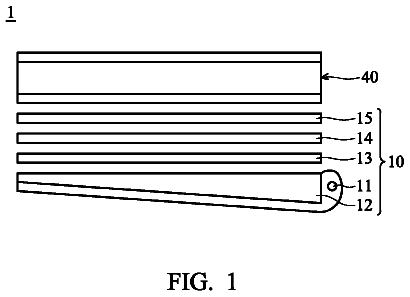
FIG. 1 is a cross-sectional schematic view of the anti-reflection film of the present invention.
FIG. 2 is a cross-sectional schematic view of the polarizing plate of the present invention, which uses the anti-reflection film of the present invention.
FIG. 3 is a cross-sectional schematic view of the transmission liquid crystal display of the present invention, which is provided with the anti-reflection film of the present invention.
Description of numerals
1 Anti-reflection film. 11 First transparent substrate. 12 Hard coat layer. 13 Low refractive index layer. 2 Polarizing plate. 22 Second transparent substrate. 23 Polarizing layer. 3 Liquid crystal cell. 4 Second polarizing plate. 41 Third transparent substrate. 42 Fourth transparent substrate. 43 Second polarizing layer. 5 Backlight unit.
Embodiment of the invention
A cross-sectional schematic view of the anti-reflection film of the present invention was shown in FIG. 1.
An anti-reflection film 1 of the present invention is sequentially provided with a hard coat layer 12 and a low refractive index layer 13 on at least one surface of a first transparent substrate 11. The hard coat layer 12 is provided on the first transparent substrate 11, so that high surface hardness may be imparted on the anti-reflection film surface to allow the anti-reflection film excellent in excoriation resistance. Further, the low refractive index layer 13 is provided on the hard coat layer 12. By means of providing the low refractive index layer with a layer thickness having an optical film thickness such as to become 1/4 of a wavelength in a visible light region, external light which enters the anti-reflection film surface maybe restrained from reflecting and contrast in a bright place may be improved. Further, visible light transmittance of the anti-reflection film may be improved, so that white luminance on the occasion of offering the liquid crystal display using this as a white indication may be improved and the contrast may be improved.
The anti-reflection film of the present invention is characterized in that
visibility-average light transmittance absorption loss of the above-mentioned anti-reflection film is within a range of 0.5% or more and 3.0% or less,
a value obtained by subtracting the minimum value of light transmittance absorption loss at each wavelength in a visible light region of the anti-reflection film from the maximum value of light transmittance absorption loss at each wavelength in a visible light region of the above-mentioned anti-reflection film is within a range of 0.5% or more and 4.0% or less, and
light transmittance absorption loss at wavelengths of 450 nm, 550 nm, and 650 nm in the anti-reflection film is Q.sub.450>Q.sub.550>Q.sub.650 (Q.sub.450: light transmittance absorption loss at a wavelength of 450 nm/Q.sub.550: light transmittance absorption loss at a wavelength of 550 nm/Q.sub.650: light transmittance absorption loss at a wavelength of 650 nm). In the present invention, the anti-reflection film which satisfies all of the requirements
to
allows the anti-reflection film, which not only has the sufficient anti-reflection performance and the sufficient excoriation resistance performance but also allows more appropriate black indication for the reason that the problem that the screen was tinged with blue on the occasion of providing this anti-reflection film is arranged on the transmission liquid crystal display surface to give the display the black indication was restrained by selecting the transmitted ray.
The anti-reflection film of the present invention is characterized in that
visibility-average light transmittance absorption loss of the above-mentioned anti-reflection film is within a range of 0.5% or more and 3.0% or less.
Light transmittance absorption loss Q.lamda. at a wavelength .lamda. of the present invention is calculated by the following expression (Expression 1). Q.lamda.=100-H-T.lamda.-R.lamda. (Expression 1) Q.lamda.: light transmittance absorption loss (%) H: haze (%) T.lamda.: spectral transmittance (%) R.lamda.: both-side reflectance (%)
Here, the both-side reflectance R.lamda. is the total of both surface reflectance Rs and rear surface reflectance Rb. The reflectance of the anti-reflection film is measured in a state that rear surface reflection is cancelled by applying black paint and the like to the rear surface, and then the rear surface is roughened with sandpaper and coated with black paint and the like, and only the surface reflectance Rs is measured by this method. Here, the both-side reflectance R.lamda. (=Rs+Rb) (at a wavelength .lamda.) may be measured by measuring spectral reflectance without canceling this rear surface reflection (without roughening and applying the black paint). As clarified from (Expression 1), light transmittance absorption loss in the present invention is not loss due to scattering but loss due to light absorption.
Haze (H) of the anti-reflection film may be measured by JIS K 7105 (1981). The spectral transmittance T.lamda. and the both-side reflectance R.lamda. at a wavelength .lamda. of the anti-reflection film are measured in such a manner that C light source is used as a light source and incident and emergent angles of the light source and a photoreceptor are set at 5.degree. from the vertical direction against the anti-reflection film surface to measure the spectral reflectance in the direct transmission direction and the regular reflection direction under the conditions of 2.degree.-visual field. The visibility-average light transmittance absorption loss Q is a value obtained by correcting and averaging the light transmittance absorption loss Q.lamda. at each wavelength of visible light with relative visibility. Then, bright-light vision standard relative visibility is used as the relative visibility.
In the anti-reflection film of the present invention, the visibility-average light transmittance absorption loss within a range of 0.5% or more and 3.0% or less allows the anti-reflection film which may provide the display excellent in contrast in a bright place and contrast in a dark place. In the case where the light transmittance absorption loss of the anti-reflection film is less than 0.5%, light leakage on the occasion of using the display as the black indication may not sufficiently be prevented, and luminance (black luminance) on the occasion of indicating a black image in a dark place becomes so high as to deteriorate the contrast in a dark place. On the other hand, in the case where the light transmittance absorption loss of the anti-reflection film is more than 3.0%, black luminance of the display may be lowered in a dark place, but luminance (white luminance) on the occasion of indicating a white image becomes so low as to occasionally deteriorate the contrast in a dark place eventually.
The anti-reflection film of the present invention is characterized in that
a value obtained by subtracting the minimum value of light transmittance absorption loss at each wavelength in a visible light region of the anti-reflection film from the maximum value of light transmittance absorption loss at each wavelength in a visible light region of the above-mentioned anti-reflection film is within a range of 0.5% or more and 4.00 or less. The value obtained by subtracting the minimum value of the light transmittance absorption loss at each wavelength from the maximum value thereof is determined within a range of 0.5% or more and 4.00 or less, so that the light transmittance absorption loss of the anti-reflection film exhibits a gentle wavelength dependence over the visible light region to allow the anti-reflection film with favorable color reproducibility on the occasion of providing this anti-reflection film on the display surface. In the case where the value obtained by subtracting the minimum value of the light transmittance absorption loss at each wavelength in the visible light region from the maximum value thereof is more than 4.0%, the anti-reflection film is provided with such a specific large light absorption wavelength over the visible light region that the image is tinted on the occasion of offering the screen as the white indication in the display using this. On the other hand, in the case where the value obtained by subtracting the minimum value of the light transmittance absorption loss at each wavelength in the visible light region from the maximum value thereof is less than 0.5%, the problem that the screen was tinged with blue on the occasion of offering the screen as the black indication may not be restrained even though this anti-reflection film is provided on the transmission liquid crystal display surface. The visible light region intended for the maximum value and the minimum value of the light transmittance absorption loss of the present invention is within a range of 400 nm or more and 700 nm or less.
The anti-reflection film of the present invention is characterized in that
light transmittance absorption loss at wavelengths of 450 nm, 550 nm, and 650 nm in the anti-reflection film is Q.sub.450>Q.sub.550>Q.sub.650 (Q.sub.450: light transmittance absorption loss at a wavelength of 450 nm/Q.sub.550: light transmittance absorption loss at a wavelength of 550 nm/Q.sub.650: light transmittance absorption loss at a wavelength of 650 nm).
The value obtained by subtracting the minimum value of the light transmittance absorption loss at each wavelength in the visible light region from the maximum value thereof is determined within a range of 0.5% or more and 4.0% or less, and
the light transmittance absorption loss at wavelengths of 450 nm, 550 nm, and 650 nm in the anti-reflection film satisfies Q.sub.450>Q.sub.550>Q.sub.650, so that the anti-reflection film of the present invention maybe provided with a gentle light absorption on the short wavelength side.
Then, the anti-reflection film of the present invention is provided with a gentle light absorption on the short wavelength side, so that the problem that the screen was tinged with blue on the occasion of offering as the black indication, the transmission liquid crystal display having as a component the polarizing plate using oriented polyvinyl alcohol, to which iodine is added, as the polarizing layer is solved while selectively restrained by providing this anti-reflection film on the observer side to allow the transmission liquid crystal display which may give more appropriate black indication. That is to say, with regard to a pair of the polarizing plates (using iodine oriented polyvinyl alcohol), blue light leakage caused on the occasion of orthogonalizing polarization directions thereof may be selectively absorbed in the anti-reflection film of the present invention, so that the problem that the screen was tinged with blue on the occasion of offering the display as the black indication may be selectively restrained by providing this anti-reflection film on the liquid crystal display surface.
Further, in the anti-reflection film of the present invention, visibility-average reflectance on the anti-reflection film surface is preferably within a range of 0.5% or more and 1.5% or less. In the case where the visibility-average reflectance is more than 1.5%, a reflection of external light which enters the anti-reflection film surface may not sufficiently be prevented, and the anti-reflection film having such a sufficient anti-reflection function as to be provided on the display surface may not be obtained. On the other hand, in the case where the visibility-average reflectance is less than 0.5%, a difference between the maximum value and the minimum value of the spectral reflectance in a range of 400 nm to 700 nm as wavelengths in the visible light region becomes so large that it occasionally becomes difficult to make a reflection hue into a neutral and tintless state and the anti-reflection film becomes so inappropriate to be provided as the display surface.
The visibility-average reflectance on the low refractive index layer side of the anti-reflection film surface of the present invention is obtained from a spectral reflectance curve. The spectral reflectance curve is obtained in such a manner that C light source is used as a light source and incident and emergent angles of the light source and a photoreceptor are set at 5.degree. from the vertical direction against the anti-reflection film surface to measure the spectral reflectance in the regular reflection direction under the conditions of 2.degree.-visual field. The spectral reflectance is measured by irradiating with measuring light on the low refractive index layer in a state that rear surface reflection is cancelled by roughening with sandpaper an opposite surface to the low refractive index layer forming surface of the anti-reflection film, which is coated with black paint. The visibility-average reflectance is a value of the reflectance obtained by correcting and averaging the reflectance at each wavelength in the visible light region with relative visibility. Then, bright-light vision standard relative visibility is used as the relative visibility.
Further, in the anti-reflection film of the present invention, it is preferable that the haze (H) of the anti-reflection film is within a range of 0.5% or less and parallel ray transmittance of the above-mentioned anti-reflection film is within a range of 94.0% or more and 96.5% or less.
The anti-reflection film with high contrast in a bright place is allowed by determining the haze of the anti-reflection film of the present invention at 0.5% or less. In the case where the haze is more than 0.5%, light leakage on the occasion of using the liquid crystal display as the black indication in a dark place may be apparently restrained by the reason of transmission loss due to scattering; however, on the occasion of the black indication in a bright place, the scattering makes the black indication into white blur to deteriorate the contrast. The haze of the anti-reflection film may be measured by JIS K 7105 (1981).
The contrast of the liquid crystal display using this anti-reflection film may be made favorable by determining the parallel ray transmittance of the anti-reflection film at 94.0% or more and 96.5% or less. In the case where the parallel ray transmittance of the anti-reflection film is less than 94.0%, white luminance on the occasion of using the display as the white indication becomes so low as to deteriorate the contrast. In addition, an improvement in the parallel ray transmittance by providing the low refractive index layer is cancelled. On the other hand, in consideration of the rear surface reflection, it is substantially difficult to produce the anti-reflection film having a parallel ray transmittance of more than 96.5%, and the anti-reflection film of the present invention is characterized in that the parallel ray transmittance is 96.5% or less. The parallel ray transmittance of the anti-reflection film may be measured by JIS K 7105 (1981).
Further, a surface resistivity on the surface of the low refractive index layer provided in the anti-reflection film of the present invention is preferably within a range of 1.0.times.10.sup.6 .OMEGA./cm.sup.2 or more and 1.0.times.10.sup.11 .OMEGA./cm.sup.2 or less. The surface resistivity on the low refractive index layer surface of the anti-reflection film of the present invention is set within the above-mentioned range, thereby an antistatic function may be provided in the anti-reflection film and adhesive dirt such as dust may be prevented from occurring on the occasion of providing the anti-reflection film on the display surface. Further, electrification on the display surface may be prevented from influencing the inside of the display. In the case where the surface resistivity on the low refractive index layer surface is more than 1.0.times.10.sup.11 (.OMEGA./cm.sup.2), the anti-reflection film having sufficient antistatic properties may not be obtained. On the other hand, in the case where the surface resistivity on the low refractive index layer surface is less than 1.0.times.10.sup.6 (.OMEGA./cm.sup.2), conductive particles need to be added into a binder matrix in large quantities for obtaining this state, and this addition is uneconomical; also, optical properties do not satisfy the properties as the anti-reflection film used for the display and occasionally become nonadjustable in the present invention.
It may be realized by adding a conductive material to the hard coat layer that the antistatic function is provided for the anti-reflection film to determine the surface resistivity within the above-mentioned range.
Further, with regard to the anti-reflection film of the present invention, the reflection hue in L*a*b* chromaticity system on the anti-reflection film surface on the side on which the above-mentioned low refractive index layer is formed, namely, the low refractive index layer surface is preferably 0.00.ltoreq.a*.ltoreq.3.00 and -3.00.ltoreq.b*.ltoreq.3.00. The reflection hue in L*a*b* chromaticity system on the anti-reflection film surface on the low refractive index layer side is set within the above-mentioned range, thereby the tintless anti-reflection film may be obtained and the display surface is used more appropriately.
The reflection hue is more colorless as a* and b* are closer to 0. However, -3.00.ltoreq.a*.ltoreq.0.00 is a green region with high relative visibility and observers tend to recognize a tint easily. Accordingly, in the anti-reflection film of the present invention, 0.00.ltoreq.a*.ltoreq.3.00 and -3.00.ltoreq.b*3.00 are preferably determined.
The reflection hue of the anti-reflection film of the present invention is measured by a spectrophotometer after applying lusterless black paint on the transparent substrate surface on the side on which the hard coat layer and the low refractive index layer are not provided. The reflection hue is obtained in such a manner that C light source is used as a light source and incident and emergent angles of the light source and a photoreceptor are determined at 5.degree. from the vertical direction against the anti-reflection film surface to measure the spectral reflectance in the regular reflection direction under the conditions of 2.degree.-visual field.
Further, with regard to the anti-reflection film of the present invention, the hard coat layer preferably contains zinc oxide-based particles. The zinc oxide-based conductive particles such as zinc oxide, aluminum-doped zinc oxide (AZO) and gallium-doped zinc oxide (GZO) exhibit a tendency such that the light transmittance absorption loss at each wavelength in the visible light region decreases as the wavelength lengthens. Accordingly, the use of the zinc oxide-based conductive particles allows the anti-reflection film to be easily produced, such that the light transmittance absorption loss at wavelengths of 450 nm, 550 nm, and 650 nm satisfies Q.sub.450>Q.sub.550>Q.sub.650. Further, the zinc oxide-based conductive particles such as zinc oxide, aluminum-doped zinc oxide (AZO) and gallium-doped zinc oxide (GZO) are preferable for the reason that the antistatic function may be provided for the anti-reflection film.
Next, a polarizing plate using the anti-reflection film of the present invention is described. A cross-sectional schematic view of the polarizing plate using the anti-reflection film of the present invention was shown in FIG. 2. The polarizing plate 2 according to the present invention has a structure such that a polarizing layer is held between two transparent substrates. The anti-reflection film of the present invention is provided with the hard coat layer and the low refractive index layer in this order on one surface of the transparent substrate. The polarizing plate 2 of the present invention is sequentially provided with a polarizing layer 23 and a second transparent substrate 22 on the other surface of a first transparent substrate 11 composing the anti-reflection film 1. That is to say, the first transparent substrate 11 composing the anti-reflection film 1 has a structure such as to serve as a transparent substrate for holding the polarizing layer 23 therebetween.
Next, a transmission liquid crystal display using the anti-reflection film of the present invention is described. A cross-sectional schematic view of the transmission liquid crystal display provided with the anti-reflection film of the present invention was shown in FIG. 3. The transmission liquid crystal display according to the present invention shown in FIG. 3 is provided with a backlight unit 5, a second polarizing plate 4, a liquid crystal cell 3, and the first polarizing plate 2 including the anti-reflection film 1 as the polarizing plate of the present invention in this order. Then, the anti-reflection film side is the observation side, that is, the display surface.
The backlight unit is provided with a light source and a light diffuser panel (not shown in FIGS.). The liquid crystal cell has a structure that an electrode is provided in one transparent substrate, an electrode and a color filter are provided in the other transparent substrate, and the liquid crystal is sealed between both of the electrodes (not shown in FIGS.). The second polarizing plate 4 has a structure that the second polarizing layer 43 is held between a third transparent substrate 41 and a fourth transparent substrate 42. The first polarizing plate 2 and the second polarizing plate 4 are provided so as to hold the liquid crystal cell 3 therebetween.
Further, the transmission liquid crystal display of the present invention may be provided with other functional members. Examples of the other functional members include a diffusion film, a prism sheet and a luminance enhancement film to use effectively the light emitted from the backlight, and a retardation film for compensating retardation of the liquid crystal cell and the polarizing plate; however, the transmission liquid crystal display of the present invention is not limited thereto.
Next, a method for producing the anti-reflection film of the present invention is described.
A film or a sheet made of various organic polymers may be used as a transparent substrate in the anti-reflection film of the present invention. Examples thereof include a substrate ordinarily used for an optical member such as display, and organic polymers, for example, polyolefins such as polyethylene and polypropylene, polyesters such as polyethylene terephthalate and polyethylene naphthalate, celluloses such as triacetyl cellulose, diacetyl cellulose and cellophane, polyamides such as 6-nylon and 6,6-nylon, acryls such as polymethyl methacrylate, polystyrene, polyvinyl chloride, polyimide, polyvinyl alcohol, polycarbonate, and ethylene vinylalcohol, in consideration of optical properties such as transparency and refractive index of light, and physical properties such as shock resistance, heat resistance and durability. In particular, polyethylene terephthalate, triacetyl cellulose, polycarbonate and polymethyl methacrylate are preferable. Above all, triacetyl cellulose may be appropriately used for the liquid crystal display by the reason of being small in birefringence and favorable in transparency.
The thickness of the transparent substrate is preferably within a range of 25 .mu.m or more and 200 .mu.m or less, more preferably within a range of 40 .mu.m or more and 80 .mu.m or less.
In addition, these organic polymers to which the function is allowed by adding publicly known addition agents such as an ultraviolet absorbing agent, an infrared absorbing agent, a plasticizer, a lubricant, a coloring agent, an antioxidant and a fire retardant may be also used. Further, the transparent substrate may be a mixture, a polymer or a laminate of plural layers of one kind or two kinds or more selected from the above-mentioned organic polymers.
Next, a method for forming the hard coat layer is described. The hard coat layer may be obtained in such a manner that a coating liquid for forming a hard coat layer containing an ionizing radiation-curable material is applied onto the transparent substrate, on which a coating film is formed and dried as required to thereafter perform a curing reaction of the an ionizing radiation-curable material by irradiating with an ionizing radiation such as ultraviolet rays and electron rays.
Examples of an application method for the coating liquid for forming the hard coat layer include an application method by using a roll coater, a reverse-roll coater, a gravure coater, a microgravure coater, a knife coater, a bar coater, a wire bar coater, a die coater and a dip coater.
An acrylic material may be used as the ionizing radiation-curable material added to the coating liquid for forming the hard coat layer. Examples of the acrylic material include a mono-functional or poly-functional(meth)acrylate compound such as acrylate or methacrylate of polyhydric alcohol, and a poly-functional urethane(meth)acrylate compound such as the ones to be synthesized from diisocyanate, polyhydric alcohol and hydroxyester of acrylic acid or methacrylic acid. In addition to these, examples of the ionizing radiation-curable material include polyether resin, polyester resin, epoxy resin, alkyd resin, spiroacetal resin, polybutadiene resin and polythiol polyene resin having an acrylate-based functional group.
In the present invention, `(meth)acrylate` represents both of `acrylate` and `methacrylate`. For example, `urethane(meth)acrylate` represents both of `urethane acrylate` and `urethane methacrylate`.
Examples of the mono-functional(meth)acrylate compound include 2-hydroxyethyl(meth)acrylate, 2-hydroxypropyl(meth)acrylate, 2-hydroxybutyl(meth)acrylate, n-butyl(meth) acrylate, isobutyl(meth) acrylate, tert-butyl(meth)acrylate, glycidyl(meth)acrylate, acryloyl morpholine, N-vinyl pyrrolidone, tetrahydrofurfuryl acrylate, cyclohexyl(meth)acrylate, 2-ethylhexyl(meth)acrylate, isobornyl(meth)acrylate, isodecyl(meth)acrylate, lauryl(meth)acrylate, tridecyl(meth)acrylate, cetyl(meth)acrylate, stearyl(meth)acrylate, benzyl(meth)acrylate, 2-ethoxyethyl(meth)acrylate, 3-methoxybutyl(meth)acrylate, ethyl carbitol(meth)acrylate, phosphoric acid(meth)acrylate, ethylene oxide modified phosphoric acid(meth)acrylate, phenoxy(meth)acrylate, ethylene oxide modified phenoxy(meth)acrylate, propylene oxide modified phenoxy(meth)acrylate, nonyl phenol(meth)acrylate, ethylene oxide modified nonyl phenol(meth)acrylate, propylene oxide modified nonyl phenol(meth)acrylate, methoxy diethylene glycol(meth)acrylate, methoxy polyethylene glycol(meth)acrylate, methoxy propylene glycol(meth)acrylate, 2-(meth)acryloyloxyethyl-2-hydroxypropyl phthalate, 2-hydroxy-3-phenoxypropyl(meth)acrylate, 2-(meth)acryloyloxyethyl hydrogen phthalate, 2-(meth)acryloyloxypropyl hydrogen phthalate, 2-(meth)acryloyloxypropyl hexahydro hydrogen phthalate, 2-(meth)acryloyloxypropyl tetrahydro hydrogen phthalate, dimethylaminoethyl(meth)acrylate, trifluoroethyl(meth)acrylate, tetrafluoropropyl(meth)acrylate, hexafluoropropyl(meth)acrylate, octafluoropropyl(meth)acrylate, octafluoropropyl(meth)acrylate, and adamantane derivative mono(meth)acrylate such as adamanthyl acrylate having monovalent mono(meth)acrylate derived from 2-adamantane or adamantane diol.
Examples of the above-mentioned di-functional(meth)acrylate compound include di(meth)acrylates such as ethylene glycol di(meth)acrylate, diethylene glycol di(meth)acrylate, butanediol di(meth)acrylate, hexanediol di(meth)acrylate, nonanediol di(meth)acrylate, ethoxylated hexanediol di(meth)acrylate, propoxylated hexanediol di(meth)acrylate, diethylene glycol di(meth)acrylate, polyethylene glycol di(meth)acrylate, tripropylene glycol di(meth)acrylate, polypropylene glycol di(meth)acrylate, neopentyl glycol di(meth)acrylate, ethoxylated neopentyl glycol di(meth)acrylate, tripropylene glycol di(meth)acrylate, and hydroxypivalic acid neopentyl glycol di(meth)acrylate.
Examples of the above-mentioned tri- or higher-functional(meth)acrylate compound include tri-functional(meth)acrylate compounds such as tri(meth)acrylates such as trimethylolpropane tri(meth)acrylate, ethoxylated trimethylolpropane tri(meth)acrylate, propoxylated trimethylolpropane tri(meth)acrylate, tris 2-hydroxyethyl isocyanurate tri(meth)acrylate and glycerin tri(meth)acrylate, pentaerythritol tri(meth)acrylate, dipentaerythritol tri(meth)acrylate, and ditrimethylolpropane tri(meth)acrylate; poly-functional or higher-functional(meth)acrylate compounds such as pentaerythritol tetra(meth)acrylate, ditrimethylolpropane tetra(meth)acrylate, dipentaerythritol tetra(meth)acrylate, dipentaerythritol penta(meth)acrylate, ditrimethylolpropane penta(meth)acrylate, dipentaerythritol hexa(meth)acrylate, and ditrimethylolpropane hexa(meth)acrylate; and poly-functional(meth)acrylate compounds such that part of these (meth)acrylates is substituted with an alkyl group or .epsilon.-caprolactone; and the like.
Among the acrylic materials, the poly-functional urethane acrylate may be appropriately used for the reason that desired molecular weight and molecular structure may be designed and the physical properties of the hard coat layer to be formed may be easily balanced. The urethane acrylate is obtained by reacting polyhydric alcohol, polyhydric isocyanate and hydroxyl group-containing acrylate. Specific examples thereof include UA-306H, UA-306T and UA-3061 manufactured by Kyoei Kagaku Kogyo Co., Ltd., UV-1700B, UV-6300B, UV-7600B, UV-7605B, UV-7640B and UV-7650B manufactured by The Nippon Synthetic Chemical Industry Co., Ltd., U-4HA, U-6HA, UA-100H, U-6LPA, U-15HA, UA-32P and U-324A manufactured by Shin Nakamura Chemical Co., Ltd., Ebecryl-1290, Ebecryl-1290K and Ebecryl-5129 manufactured by DAICEL-UCB Company LTD., and UN-3220HA, UN-3220HB, UN-3220HC and UN-3220HS manufactured by Negami Chemical Industrial Co., Ltd., and are not limited thereto.
In addition to these, examples of the ionizing radiation-curable material include polyether resin, polyester resin, epoxy resin, alkyd resin, spiroacetal resin, polybutadiene resin and polythiol polyene resin having an acrylate-based functional group.
Further, in the case where the coating liquid for forming the hard coat layer is cured by ultraviolet rays, a photopolymerization initiator is added to the coating liquid for forming the hard coat layer. The photopolymerization initiator maybe such as to generate a radical while irradiated with ultraviolet rays, and examples thereof include acetophenones, benzoins, benzophenones, phosphine oxides, ketals, anthraquinones and thioxanthones. Further, the added amount of the photopolymerization initiator is 0.1 part by weight or more and 10 parts by weight or less, preferably 1 part by weight or more and 7 parts by weight or less with respect to 100 parts by weight of the ionizing radiation-curable material.
Further, a light-absorbing material is added to the coating liquid for forming the hard coat layer so that the visibility-average light transmittance absorption loss of the anti-reflection film is within a range of 0.5% or more and 3.0% or less, the value obtained by subtracting the minimum value of the light transmittance absorption loss at each wavelength in the visible light region of the anti-reflection film from the maximum value thereof is 4.0% or less, and the light transmittance absorption loss at wavelengths of 450 nm, 550 nm, and 650 nm in the anti-reflection film satisfies Q.sub.450>Q.sub.550>Q.sub.650.
The description continues in the full USPTO document.
 Lapsed, fee not paid34 drawings