Technical field
The present invention relates to an antenna evaluation apparatus for evaluating the performance of an antenna of a wireless communication apparatus, and relates to an antenna evaluation method using the same antenna evaluation apparatus.
Background art
In recent years, wireless terminal apparatuses for mobile communication such as mobile phones have been rapidly developed. When a radio wave arrives at a wireless terminal apparatus from a base station, the radio wave includes multipath waves produced from reflection, scattering, diffraction, or the like due to terrain, structures, and the like in its propagation path, and the radio wave has randomly changing amplitude and phase depending on the location. When receiving a radio wave from the base station as well as moving within its propagation path, fading (i.e., signal level drops, including variation in instantaneous values) occurs due to multipath propagation of the radio wave. As a result, a digital communication environment suffers from increased errors in codes and significant degradation of transmission quality (see Non-Patent Literature 1). Thus, if evaluating the communication performance of a wireless terminal apparatus, it is desirable not only to evaluate its static characteristics in an RF anechoic chamber, but also to evaluate its performance in a multipath propagation environment. Hence, the applicant of the present application proposed antenna evaluation apparatuses (also referred to as "spatial multipath waves generating apparatuses" or "fading emulators") such as those described in Patent Literature 1 and Non-Patent Literatures 2 to 5.
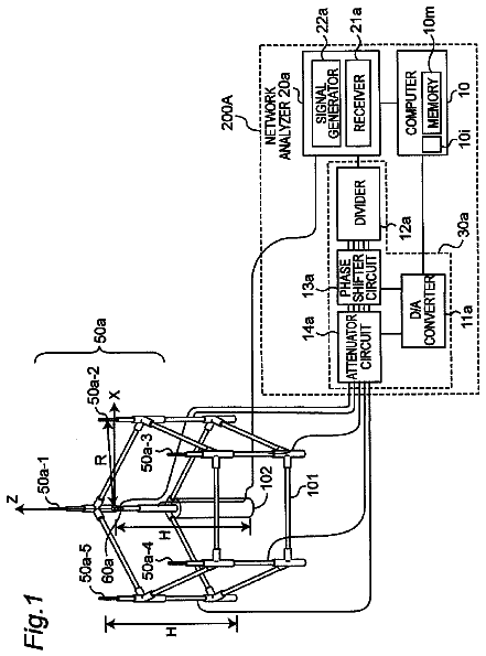
FIG. 32 is a block diagram showing a configuration of a prior art antenna evaluation apparatus described in Patent Literature 1. The antenna evaluation apparatus includes: a plurality of transmitting antennas (referred to as "scatterer antennas" hereinafter) 121-1 to 121-7 disposed at regular intervals on the circumference of a circle with a radius r; an antenna under measurement 122 disposed near a center of the circle, such as a diversity antenna; and a control and measurement apparatus 100 connected thereto. The control and measurement apparatus 100 includes: a network analyzer 111, a divider 112, a phase-shift circuit 113, an attenuation circuit 114, a D/A converter 115, and a computer 110. The network analyzer 111 generates a radio frequency signal, and the divider 112 divides the generated radio frequency signal in accordance with the number of the scatterer antennas 121-1 to 121-7. The phase-shift circuit 113 and the attenuation circuit 114 adjust the phases and amplitudes of the divided radio frequency signals. The adjusted radio frequency signals are radiated from the scatterer antennas 121-1 to 121-7, respectively. Radio frequency signals received by the antenna under measurement 122 are inputted to the network analyzer 111. The computer 110 controls the network analyzer 111 and controls the amounts of phase adjustments made by the phase-shift circuit 113 and the amounts of amplitude adjustments (amounts of attenuation) made by the attenuation circuit 114 through the D/A converter 115. The antenna evaluation apparatus controls the amplitudes and phases of radio frequency signals to be radiated from the scatterer antennas 121-1 to 121-7, and thus controls the property of a multipath propagation environment (a fading environment, etc.) which is formed around the center of the circle by the radiated radio frequency signals. Then, a performance in an actual use environment is evaluated by the antenna under measurement 122 disposed near the center of the circle.
In addition, in recent years, a MIMO (Multi-Input Multi-Output) antenna apparatus for transmitting and receiving radio signals of a plurality of channels using a plurality of antenna elements simultaneously has been developed. FIG. 33 is a schematic diagram showing a MIMO wireless communication system including: a MIMO transmitter 200 with two transmitting antennas 201 and 202; and a MIMO receiver 210 with two receiving antennas 211 and 212. The MIMO transmitter 200 converts a data stream to be transmitted into a plurality of (in this case, two) substreams, and transmits the respective substreams from corresponding transmitting antennas 201 and 202. In this case, a first substream transmitted from the transmitting antenna 201 travels through a first channel 221 and arrives at the receiving antenna 211, and travels through a second channel 222 and arrives at the receiving antenna 212. Likewise, a second substream transmitted from the transmitting antenna 202 travels through a third channel 223 and arrives at the receiving antenna 211, and travels through a fourth channel 224 and arrives at the receiving antenna 212.
Citation list
Patent Literature
PATENT LITERATURE 1: Japanese Patent Laid-open Publication No. 2005-227213. PATENT LITERATURE 2: Japanese Patent No. 3816499.
Non-Patent Literature
NON-PATENT LITERATURE 1: Yoshio Karasawa, "Radiowave Propagation Fundamentals for Digital Mobile Communications", CORONA PUBLISHING CO., LTD., pp. 5-8, March 2003. NON-PATENT LITERATURE 2: Tsutomu Sakata et al., "Evaluation of Mobile Terminal Antennas using Spatial Fading Emulator", Matsushita Technical Journal, Vol. 52, No. 5, pp. 70-75, October 2006. NON-PATENT LITERATURE 3: Tsutomu Sakata et al., "Channel Capacity Measurements of a MIMO Antenna under a Rayleigh-fading Channel by a Spatial Fading Emulator", Proceedings of the 2007 IEICE Society Conference, B-1-9, September 2007. NON-PATENT LITERATURE 4: Tsutomu Sakata et al., "A Multipath Measurement System with a Variable Power Angular Spectrum for Handset MIMO Antennas", IEICE Technical Report, Vol. 108, No. 5, pp. 13-18, April 2008. NON-PATENT LITERATURE 5: Tsutomu Sakata et al., "An Evaluation of the MIMO Transmission Characteristics in a Cluster Propagation Environment Using a Spatial Fading Emulator", IEICE Technical Report, Vol. 108, No. 429, pp. 121-126, April 2009.
Summary of invention
When evaluating an antenna's performance in a multipath propagation environment, it is necessary to consider differences among propagation times of radio waves traveling various propagation paths, i.e., delays due to the multipath.
Further, if using the antenna evaluation apparatus of FIG. 32 to evaluate the performance of the MIMO wireless communication system of FIG. 33, it is necessary to create different multipath propagation environments for different substreams transmitted from the MIMO transmitter, under an assumption that the substreams travel different propagation paths.
At present, standardization of methods for measuring wireless communication systems is in progress in the EU. A sophisticated radio wave model called "SCME (Spatial Channel Model Extended)" is likely to be standardized. SCME defines a model including a plurality of delayed waves. The different delayed waves need to produce different fadings, preferably, fadings having no correlation with each other.
An object of the present invention is to solve the above-described problems, and provide an antenna evaluation apparatus capable of creating a multipath propagation environment including fadings and delays due to multipath propagation of radio waves, when evaluating the performance of receiving antennas of a MIMO wireless communication system, as well as provide an antenna evaluation method using the same antenna evaluation apparatus.
According to the first aspect of the present invention, an antenna evaluation apparatus is provided, having a receiving antenna to be evaluated and a plurality of scatterer antennas provided around the receiving antenna. The antenna evaluation apparatus is provided with: a plurality of signal generators each generating a radio frequency signal; delaying means for adding delay times independent from each other to the generated respective radio frequency signals, and outputting resulting radio frequency signals; dividing means for dividing each of the radio frequency signals outputted from the delaying means; first radio frequency circuit means for adjusting phases and amplitudes of the divided respective radio frequency signals; and control means for controlling the delaying means to add the delay times to the generated respective radio frequency signals, and controlling the first radio frequency circuit means to change the phases and amplitudes of the divided respective radio frequency signals to produce a first fading. With respect to each of the radio frequency signals generated by the signal generators, the antenna evaluation apparatus radiates the radio frequency signals whose phases and amplitudes are adjusted by the first radio frequency circuit means, from the scatterer antennas, thus creating multipath waves including delay and the first fading around the receiving antenna.
The antenna evaluation apparatus is further provided with a plurality of combiners, each combining the radio frequency signals whose phases and amplitudes are adjusted by the first radio frequency circuit means, so as to combine the radio frequency signals corresponding to the respective radio frequency signals generated by the different signal generators. At least one of the scatterer antennas radiates the combined radio frequency signals.
Moreover, in the antenna evaluation apparatus, the first radio frequency circuit means includes a plurality of phase-shift means and a plurality of amplitude adjusting means. The antenna evaluation apparatus is further provided with a plurality of combiners, and each of the combiners combines the radio frequency signals which are divided by the dividing means and whose phases are adjusted by the respective phase-shift means, so as to combine the radio frequency signals corresponding to the respective radio frequency signals generated by the different signal generators. Each of the amplitude adjusting means adjusts an amplitude of a corresponding one of the combined radio frequency signals.
Further, the antenna evaluation apparatus is further provided with a combiner for combining the radio frequency signals generated by the signal generators, and sending the combined radio frequency signal to the dividing means. Each of the radio frequency signals divided by the dividing means includes the radio frequency signals corresponding to the respective radio frequency signals generated by the different signal generators.
Furthermore, the antenna evaluation apparatus is further provided with second radio frequency circuit means being provided between the dividing means and the first radio frequency circuit means, for adjusting the phases and amplitudes of the divided respective radio frequency signals. The control means controls the second radio frequency circuit means to adjust the phases and amplitudes of the radio frequency signals to set a distribution of incoming waves.
Moreover, in the antenna evaluation apparatus, the delaying means further generates at least one delayed radio frequency signal from each of the radio frequency signals generated by the signal generators, adds second fadings different from each other to each of the generated radio frequency signals and to each of the delayed radio frequency signals, respectively, combines the radio frequency signals to which the second fadings are added, and outputs the combined radio frequency signals.
Further, in the antenna evaluation apparatus, the second fadings different from each other have no correlation with each other.
Furthermore, in the antenna evaluation apparatus, the delaying means includes fading simulators.
According to the second aspect of the present invention, an antenna evaluation apparatus is provided, having a receiving antenna to be evaluated and a plurality of scatterer antennas provided around the receiving antenna, the scatterer antennas being arranged to make M sets of scatterer antennas, each set of scatterer antennas including a number of the scatterer antennas, each set of scatterer antennas being provided close together in one of a plurality of M directions toward the receiving antenna. The antenna evaluation apparatus is provided with: a plurality of signal generators each generating a radio frequency signal; first dividing means for outputting M radio frequency signals, each outputted radio frequency signal including the radio frequency signals generated by the respective signal generators; M delaying means for adding delay times independent from each other to the M respective radio frequency signals outputted from the first dividing means, and outputting resulting radio frequency signals; M second dividing means each dividing a corresponding one of the M radio frequency signals outputted from the respective delaying means; M radio frequency circuit means each adjusting phases and amplitudes of the radio frequency signals divided by a corresponding one of the M second dividing means; and control means for controlling the M respective delaying means to acid the delay times to the M respective radio frequency signal outputted from the first dividing means, and controlling each of the M radio frequency circuit means to change the phases and amplitudes of the radio frequency signals divided by a corresponding one of the M second dividing means to produce a fading. With respect to each of the M radio frequency signals outputted from the first dividing means, the antenna evaluation apparatus radiates the radio frequency signals whose phases and amplitudes are adjusted by a corresponding one of the radio frequency circuit means, from the scatterer antennas included in a corresponding set of the M sets of scatterer antennas, thus creating clusters of incoming waves around the receiving antenna, and creating multipath waves including delay and the fading around the receiving antenna.
According to the third aspect of the present invention, an antenna evaluation apparatus is provided, having a receiving antenna to be evaluated and a plurality of scatterer antennas provided around the receiving antenna, the scatterer antennas being arranged to make M sets of scatterer antennas, each set of scatterer antennas including a number of the scatterer antennas, each set of scatterer antennas being provided close together in one of a plurality of M directions toward the receiving antenna. The antenna evaluation apparatus is provided with: a plurality of signal generators each generating a radio frequency signal; first dividing means for outputting M radio frequency signals, each outputted radio frequency signal including the radio frequency signals generated by the respective signal generators; M delaying means for adding delay times independent from each other and amounts of phase adjustment independent from each other, to the M respective radio frequency signals outputted from the first dividing means, and outputting resulting radio frequency signals; M second dividing means each dividing a corresponding one of the M radio frequency signals outputted from the respective delaying means; M radio frequency circuit means each adjusting amplitudes of the radio frequency signals divided by a corresponding one of the M second dividing means; and control means for controlling the M respective delaying means to add the delay times to the M respective radio frequency signal outputted from the first dividing means, and controlling the M respective radio frequency circuit means and the M respective delaying means to change the phases and amplitudes of the corresponding radio frequency signals to produce a fading. With respect to each of the M radio frequency signals outputted from the first dividing means, the antenna evaluation apparatus radiates the radio frequency signals whose phases and amplitudes are adjusted by a corresponding one of the radio frequency circuit means, from the scatterer antennas included in a corresponding set of the M sets of scatterer antennas, thus creating clusters of incoming waves around the receiving antenna, and creating multipath waves including delay and the fading around the receiving antenna.
In the antenna evaluation apparatus, each of the delaying means is a fading simulator.
According to the fourth aspect of the present invention, an antenna evaluation apparatus is provided, having a receiving antenna to be evaluated and a plurality of scatterer antennas provided around the receiving antenna, the scatterer antennas being arranged to make M sets of scatterer antennas, each set of scatterer antennas including a number of the scatterer antennas, each set of scatterer antennas being provided close together in one of a plurality of M directions toward the receiving antenna. The antenna evaluation apparatus is provided with: a plurality of signal generators each generating a radio frequency signal; a plurality of signal processing means each processing a corresponding one of the generated radio frequency signals; and control means. Each of the signal processing means includes: first dividing means for dividing a corresponding one of the generated radio frequency signals; a plurality of delaying means for adding delay times independent from each other to the respective radio frequency signals divided by the first dividing means, and outputting resulting radio frequency signals; a plurality of second dividing means each dividing a corresponding one of the radio frequency signals outputted from the respective delaying means; and a plurality of radio frequency circuit means each adjusting phases and amplitudes of the radio frequency signals divided by a corresponding one of the second dividing means. The control means controls the respective delaying means to add the delay times to the respective radio frequency signal divided by the first dividing means, and controls each of the radio frequency circuit means to change the phases and amplitudes of the radio frequency signals divided by a corresponding one of the second dividing means to produce a first fading. With respect to each of the radio frequency signals divided by the first dividing means, the antenna evaluation apparatus radiates the radio frequency signals whose phases and amplitudes are adjusted by a corresponding one of the radio frequency circuit means, from the scatterer antennas included in a corresponding set of the sets of scatterer antennas, thus creating clusters of incoming waves around the receiving antenna, and creating multipath waves including delay and the first fading around the receiving antenna.
The antenna evaluation apparatus is further provided with a plurality of combiners, each combining the radio frequency signals whose phases and amplitudes are adjusted by the first radio frequency circuit means, so as to combine the radio frequency signals corresponding to the respective radio frequency signals generated by the different signal generators. At least one of the scatterer antennas radiates the combined radio frequency signals.
In the antenna evaluation apparatus, each of the delaying means further generates at least one delayed radio frequency signal from a corresponding one of the radio frequency signals divided by the first dividing means, adds second fadings different from each other to the corresponding one of the divided radio frequency signals and to the delayed radio frequency signal, respectively, combines the radio frequency signals to which the second fadings are added, and outputs the combined radio frequency signal.
In the antenna evaluation apparatus, the second fadings different from each other have no correlation with each other.
In the antenna evaluation apparatus, each of the delaying means is a fading simulator.
Moreover, in the antenna evaluation apparatus, the radio frequency signals are radio frequency signals transmitted using a MIMO communication scheme.
According to the fifth aspect of the present invention, an antenna evaluation method is provided for evaluating a receiving antenna by using an antenna evaluation apparatus including the receiving antenna to be evaluated and a plurality of scatterer antennas provided around the receiving antenna. The antenna evaluation apparatus is provided with: a plurality of signal generators each generating a radio frequency signal; delaying means for adding delay times independent from each other to the generated respective radio frequency signals, and outputting resulting radio frequency signals; dividing means for dividing each of the radio frequency signals outputted from the delaying means; and radio frequency circuit means for adjusting phases and amplitudes of the divided respective radio frequency signals. The antenna evaluation method includes the steps of: controlling the delaying means to add the delay times to the generated respective radio frequency signals, and controlling the radio frequency circuit means to change the phases and amplitudes of the divided respective radio frequency signals to produce a fading, with respect to each of the radio frequency signals generated by the signal generators, radiating the radio frequency signals whose phases and amplitudes are adjusted by the first radio frequency circuit means, from the scatterer antennas, thus creating multipath waves including delay and the first fading around the receiving antenna.
According to the antenna evaluation apparatus and the antenna evaluation method of the present invention, when evaluating the performance of receiving antennas of a MIMO wireless communication system, it is possible to create a multipath propagation environment including different fadings and different delays for different substreams transmitted from a MIMO transmitter, under an assumption that the substreams travel different propagation paths.
Moreover, according to the antenna evaluation apparatus and the antenna evaluation method of the present invention, when evaluating the performance of receiving antennas of a MIMO wireless communication system, it is possible to create a multipath propagation environment having different angle of arrival for different clusters (spatial clusters) and different delay times for different clusters (temporal clusters), under an assumption that incoming waves for different clusters travel different propagation paths.
Further, according to the antenna evaluation apparatus and the antenna evaluation method of the present invention, when evaluating the performance of receiving antennas of a MIMO wireless communication system, it is possible to produce spatial fadings, and at the same time, to produce different fadings for different delayed waves (preferably, fadings having no correlation with each other).
Brief description of drawings
FIG. 1 is a block diagram showing a configuration of an antenna evaluation apparatus according to a first embodiment of the present invention.
FIG. 2 is a block diagram showing a detailed configuration of a delay circuit 12a of FIG. 1.
FIG. 3 is a plan view showing an arrangement of antennas for the antenna evaluation apparatus of FIG. 1.
FIG. 4 is a block diagram showing a configuration of an antenna evaluation apparatus according to a first modified embodiment of the first embodiment of the present invention.
FIG. 5 is a plan view showing an arrangement of antennas for the antenna evaluation apparatus of FIG. 4.
FIG. 6 is a block diagram showing a configuration of an antenna evaluation apparatus according to a second modified embodiment of the first embodiment of the present invention.
FIG. 7 is a block diagram showing a configuration of an antenna evaluation apparatus according to a third modified embodiment of the first embodiment of the present invention.
FIG. 8 is a block diagram showing a configuration of an antenna evaluation apparatus according to a fourth modified embodiment of the first embodiment of the present invention.
FIG. 9 is a block diagram showing a configuration of an antenna evaluation apparatus according to a second embodiment of the present invention.
FIG. 10 is a schematic diagram showing clusters of incoming waves in an exemplary MIMO wireless communication system.
FIG. 11 is a block diagram showing a configuration of an antenna evaluation apparatus according to a first modified embodiment of the second embodiment of the present invention.
FIG. 12 is a plan view showing an arrangement of antennas for the antenna evaluation apparatus of FIG. 11 and showing clusters of incoming waves C-1, C-2, . . . , C-M.
FIG. 13 is a block diagram showing a configuration of an antenna evaluation apparatus according to a second modified embodiment of the second embodiment of the present invention.
FIG. 14 is a block diagram showing a detailed configuration of a fading circuit 91-1 of FIG. 13.
FIG. 15 is a block diagram showing a configuration of an antenna evaluation apparatus according to a third embodiment of the present invention.
FIG. 16 is a schematic diagram illustrating the presence of a plurality of delayed waves.
FIG. 17 is a graph showing a state in which a first wave and a second wave of FIG. 16 include different fadings.
FIG. 18A is a graph showing a first example illustrating the production of fadings, and showing a first fading produced by a fading circuit 91a of FIG. 15.
FIG. 18B is a graph showing the first example illustrating the production of fadings, and showing a second fading produced by the fading circuit 91a of FIG. 15.
FIG. 18C is a graph showing the first example illustrating the production of fadings, and showing a fading produced by a phase-shift circuit 14a and an attenuation circuit 15a of FIG. 15.
FIG. 19A is a graph showing a fading obtained by combining the fadings shown in FIGS. 18A and 18C.
FIG. 19B is a graph showing a fading obtained by combining the fadings shown in FIGS. 18B and 18C.
FIG. 20A is a graph showing a second example illustrating the production of fadings, and showing a first fading produced by the fading circuit 91a of FIG. 15.
FIG. 20B is a graph showing the second example illustrating the production of fadings, and showing a second fading produced by the fading circuit 91a of FIG. 15.
FIG. 20C is a graph showing the second example illustrating the production of fadings, and showing a fading produced by the phase-shift circuit 14a and the attenuation circuit 15a of FIG. 15.
FIG. 21A is a graph showing a fading obtained by combining the fadings shown in FIGS. 20A and 20C.
FIG. 21B is a graph showing a fading obtained by combining the fadings shown in FIGS. 20B and 20C.
FIG. 22 is a block diagram showing a configuration of an antenna evaluation apparatus according to a first modified embodiment of the third embodiment of the present invention.
FIG. 23 is a block diagram showing a configuration of an antenna evaluation apparatus according to a second modified embodiment of the third embodiment of the present invention.
FIG. 24 is a block diagram showing a configuration of an antenna evaluation apparatus according to a third modified embodiment of the third embodiment of the present invention.
FIG. 25 is a block diagram showing a configuration of an antenna evaluation apparatus according to a fourth modified embodiment of the third embodiment of the present invention.
FIG. 26 is a block diagram showing a configuration of an antenna evaluation apparatus according to a third modified embodiment of the second embodiment of the present invention.
FIG. 27 is a block diagram showing a detailed configuration of a signal processing circuit 401a of FIG. 26.
FIG. 28 is a plan view showing an arrangement of antennas for the antenna evaluation apparatus of FIG. 26 and showing clusters of incoming waves Ca-1, Cb-1, . . . , Cb-M.
FIG. 29 is a plan view showing a modified embodiment of an arrangement of antennas for the antenna evaluation apparatus of FIG. 26 and showing clusters of incoming waves C-1, C-2, . . . , C-M.
FIG. 30 is a block diagram showing a detailed configuration of a signal processing circuit 401a of an antenna evaluation apparatus according to a fourth modified embodiment of the second embodiment of the present invention.
FIG. 31 is a block diagram showing a configuration of an antenna evaluation apparatus according to a fifth modified embodiment of the second embodiment of the present invention.
FIG. 32 is a block diagram showing a configuration of a prior art antenna evaluation apparatus.
FIG. 33 is a schematic diagram showing a MIMO wireless communication system.
Detailed description of invention
Embodiments according to the present invention will be described below with reference to the drawings. Note that in the following embodiments like components are denoted by the same reference numerals.
First Embodiment
FIG. 1 is a block diagram showing a configuration of an antenna evaluation apparatus according to a first embodiment of the present invention. The antenna evaluation apparatus includes: two receiving antennas 22a and 22b disposed to be close to each other; and a plurality of scatterer antennas 21a-1 to 21a-N and 21b-1 to 21b-N disposed to surround the receiving antennas 22a and 22b. In the present embodiment, the two receiving antennas 22a and 22b are provided as, for example, two receiving antennas of a MIMO receiver to be evaluated. In addition, the scatterer antennas 21a-1 to 21a-N create multipath waves around the receiving antennas 22a and 22b, the multipath waves corresponding to, for example, a first substream radiated from a first transmitting antenna of a MIMO transmitter having two transmitting antennas and transmitting two substreams. The scatterer antennas 21b-1 to 21b-N create multipath waves around the receiving antennas 22a and 22b, the multipath waves corresponding to a second substream radiated from a second transmitting antenna of the same MIMO transmitter. Thus, the antenna evaluation apparatus of the present embodiment creates a multipath propagation environment in a MIMO wireless communication system including the MIMO transmitter with the two transmitting antennas and the MIMO receiver with the two receiving antennas, as shown in FIG. 33.
In the antenna evaluation apparatus of FIG. 1, signal generators 11a and 11b generate certain modulated radio frequency signals which respectively correspond to the two substreams transmitted from the MIMO transmitter, and which have no correlation with each other (or are orthogonal to each other). The signal generators 11a and 11b are followed by delay circuits 12a and 12b, respectively. In the present embodiment, under an assumption that the substreams transmitted from the MIMO transmitter travel various propagation paths, given delay times independent from each other are added to the substreams. The delay circuits 12a and 12b are followed by dividers 13a and 13b, respectively. The divider 13a divides a radio frequency signal inputted from the delay circuit 12a into N radio frequency signals in accordance with the number of the scatterer antennas 21a-1 to 21a-N. Likewise, the divider 13b divides a radio frequency signal inputted from the delay circuit 12b into N radio frequency signals in accordance with the number of the scatterer antennas 21b-1 to 21b-N. The divider 13a is followed by a phase-shift circuit 14a including phase shifters 14a-1 to 14a-N and an attenuation circuit 15a including attenuators 15a-1 to 15a-N. The phase shifters 14a-1 to 14a-N and the attenuators 15a-1 to 15a-N adjust the phases and amplitudes of the corresponding divided radio frequency signals. The adjusted radio frequency signals are radiated from the corresponding scatterer antennas 21a-1 to 21a-N. Likewise, the divider 13b is followed by a phase-shift circuit 14b including phase shifters 14b-1 to 14b-N and an attenuation circuit 15b including attenuators 15b-1 to 15b-N. The phase shifters 14b-1 to 14b-N and the attenuators 15b-1 to 15b-N adjust the phases and amplitudes of the corresponding divided radio frequency signals. The adjusted radio frequency signals are radiated from the corresponding scatterer antennas 21b-1 to 21b-N. The radiated 2N radio frequency signals are superposed as multipath waves around the center space surrounded by the scatterer antennas 21a-1 to 21a-N and 21b-1 to 21b-N, and the multipath waves arrive at the receiving antennas 22a and 22b. The radio frequency signals having arrived at the receiving antennas 22a and 22b are measured by receivers 17a and 17b, respectively. A computer 10 controls the signal generators 11a and 11b, controls the delay times of the delay circuits 12a and 12b, controls the amounts of phase adjustment by the phase-shift circuit 14a and the amounts of amplitude adjustment (the amounts of attenuation) by the attenuation circuit 15a through a D/A converter 16a, and controls the amounts of phase adjustment by the phase-shift circuit 14b and the amounts of amplitude adjustment (the amounts of attenuation) by the attenuation circuit 15b through a D/A converter 16b. The computer 10 also obtains results of the measurements of the radio frequency signals from the receivers 17a and 17b. Further, the signal generators 11a and 11b and the receivers 17a and 17b are synchronized with each other using in a well known manner.
FIG. 2 is a block diagram showing a detailed configuration of the delay circuit 12a of FIG. 1. The delay circuit 12a of the present embodiment operates in a baseband for delaying signals. Specifically, in the delay circuit 12a, a radio frequency signal inputted from the signal generator 11a is firstly converted from a radio frequency (RF) to a baseband frequency (BB) by a frequency converter 12aa, and the baseband signal is sent to a delay processing circuit 12ab. The delay processing circuit 12ab is configured from a well known delay element such as an electrical delay line or a FIFO memory, and delays the inputted baseband signal by a given time under the control of the computer 10. The delayed signal is converted from the baseband frequency (BB) to the radio frequency (RF) by a frequency converter 12ac, and the radio frequency signal is sent to the divider 13a. The other delay circuit 12b is also configured in the same manner as that of the delay circuit 12a.
FIG. 3 is a plan view showing an arrangement of antennas for the antenna evaluation apparatus of FIG. 1. As shown in FIG. 3, the scatterer antennas 21a-1 to 21a-N and 21b-1 to 21b-N are disposed on the circumference of a circle with a radius r so as to be spaced in angle from each other, and the two receiving antennas 22a and 22b are disposed near a center of the circle. Let a direction of the scatterer antenna 21a-1 from the center of the circle have an angle .phi..sub.1=0 as a reference direction, let a direction of the scatterer antenna 21a-2 have an angle .phi..sub.2, let a direction of the scatterer antenna 21a-3 have an angle .phi..sub.3, and similarly, let a direction of the scatterer antenna 21a-N have an angle .phi..sub.N. On the circumference of the circle, the scatterer antenna 21b-1 is located remote from the scatterer antenna 21a-1 by a distance d (e.g., a distance equal to one-half wavelength of radio frequency signals to be transmitted), the scatterer antenna 21b-2 is located remote from the scatterer antenna 21a-2 by the distance d, the scatterer antenna 21b-3 is located remote from the scatterer antenna 21a-3 by the distance d, and similarly, the scatterer antenna 21b-N is located remote from the scatterer antenna 21a-N by the distance d. The arrangement of the scatterer antennas 21a-1 to 21a-N and 21b-1 to 21b-N is not limited to that shown in FIG. 3, and any arrangement may be used as long as desired multipath waves can be created around the receiving antennas 22a and 22b. For example, the scatterer antennas 21a-1 to 21a-N and 21b-1 to 21b-N may be disposed on the circumference of a circle at an equal angular width. The receiving antennas 22a and 22b are spaced apart from each other by a distance (e.g., a distance equal to one-half wavelength of radio frequency signals to be received) according to the structure of a MIMO receiver to be evaluated. The scatterer antennas 21a-1 to 21a-N and 21b-1 to 21b-N are mounted at a height H from the floor, for example, using a scatterer antenna support 101 shown in FIG. 32. Likewise, the receiving antennas 22a and 22b are mounted at the height H from the floor, for example, using a receiving antenna support 102 shown in FIG. 32. In the present embodiment, each of the scatterer antennas 21a-1 to 21a-N and 21b-1 to 21b-N and the receiving antennas 22a and 22b is configured as, for example, a half-wavelength dipole antenna, but is not limited thereto. In addition, each of the scatterer antennas 21a-1 to 21a-N and 21b-1 to 21b-N and the receiving antennas 22a and 22b is mounted, for example, vertically to the floor and transmits and receives vertically polarized radio waves, but the arrangement is not limited thereto.
In the antenna evaluation apparatus of the present embodiment, the computer 10 controls the delay circuits 12a and 12b to add given delay times independent from each other to radio frequency signals generated by the respective signal generators 11a and 11b, controls the phase-shift circuit 14a and the attenuation circuit 15a to change the phases and amplitudes of radio frequency signals divided by the divider 13a so as to produce a fading, and controls the phase-shift circuit 14b and the attenuation circuit 15b to change the phases and amplitudes of radio frequency signals divided by the divider 13b so as to produce a fading. Further, the antenna evaluation apparatus of the present embodiment is characterized by radiating radio frequency signals generated by the signal generator 11a from the scatterer antennas 21a-1 to 21a-N to create multipath waves including delays and fadings around the receiving antennas 22a and 22b, and radiating a radio frequency signal generated by the signal generator 11b from the scatterer antennas 21b-1 to 21b-N to create multipath waves including delays and fadings around the receiving antennas 22a and 22b. Thus, according to the antenna evaluation apparatus of the present embodiment, when evaluating the performance of receiving antennas of a MIMO wireless communication system, under an assumption that substreams transmitted from a MIMO transmitter travel various propagation paths, it is possible to create a multipath propagation environment including different fadings and different delays for the different substreams.
Now, operating principles for the antenna evaluation apparatus of the present embodiment to create a multipath propagation environment including fadings will be described.
The description continues in the full USPTO document.
 Lapsed, fee not paid19 drawings