This is a 371 national phase application of PCT/JP2008/072558 filed 11 Dec. 2008, which claims priority to Japanese Patent Application No. 2007-328981 filed 20 Dec. 2007, the contents of which are incorporated herein by reference.
Field of the invention
The present invention relates to a fuel cell system. More particularly, it relates to a fuel cell system which judges the degradation of an electrolyte of a fuel cell based on an air supply amount.
Background of the invention
When a fuel cell system is operated for a long period of time, an electrolyte of a fuel cell stack degrades, an electrolyte membrane cracks, and differential pressure resistant properties lower, thereby causing cross leak sometimes. To solve this problem, heretofore, a system for detecting the occurrence of the cross leak has been developed. For example, Japanese Patent Application Laid-Open No. 2006-120375 discloses a fuel cell system in which when the concentration of hydrogen in air discharged from a fuel cell stack is not less than a predetermined value, it is judged that cross leak has occurred, to urgently stop a fuel cell (Patent Literature 1).
Moreover, another system has been developed in which during light loading or during idling, the power generation voltage of the fuel cell might rise to promote the degradation of the fuel cell, and hence the rise of the power generation voltage of a fuel cell is suppressed, thereby suppressing the degradation of the fuel cell (hereinafter processing to prevent the voltage of the fuel cell from rising to a constant value or more will be referred to as the "high-potential-avoiding processing"). For example, Japanese Patent Application Laid-Open No. 2007-109569 discloses still another fuel cell system in which as means for suppressing the degradation of a fuel cell by the high-potential-avoiding processing, an air compressor is operated so that a cell voltage is not more than a beforehand set predetermined upper limit voltage, and is controlled to intermittently supply air to a fuel cell stack (Patent Literature 2).
Furthermore, for example, Japanese Patent Application Laid-Open No. 2007-103023 discloses a further fuel cell system in which as a measure for preventing cross leak from occurring at the stop of the system, a technology is used to dispose of hydrogen crossing over an anode and accumulated in a cathode when the system is left to stand after the stop. At the start of a fuel cell, an oxidant gas is supplied under pressure until a predetermined pressure is obtained, and the gas is sealed between a shut valve and an air pressure regulation valve, whereby hydrogen present in a cathode path is burnt and treated on a catalyst in the cathode (Patent Literature 3).
In addition, there is another technology in which when the electrolyte membrane degrades owing to the adsorption of oxygen, the output voltage of the fuel cell is lowered while suppressing the supply of air, to operate the fuel cell in a reduction region, thereby activating a catalyst layer (this processing will hereinafter be referred to as the "catalyst activation processing"). As a technology concerned with such catalyst activation processing of the fuel cell, for example, Japanese Patent Application Laid-Open No. 2003-115318 discloses a technology in which a cell voltage is set to 0.6 V or less, and a large current is allowed to flow to cause a reducing reaction in oxygen, thereby activating a platinum catalyst layer (Patent Literature 4).
Moreover, if the amount of water included in cells constituting the fuel cell is not controlled in an appropriate range, the cells excessively dry, or a wet degree thereof is excessively high, thereby accelerating the degradation of the cells. To solve the problem, Japanese Patent Application Laid-Open No. 2005-32587 discloses a technology in which a relationship between the water content state of the cells and the open circuit voltage thereof is utilized. When the open circuit voltage of the cells is lower than a first threshold voltage, it is judged that the cells have a dry state. When the open circuit voltage is higher than a second threshold voltage, it is judged that the cells have an excessive water state, and the water content state of the cells is appropriately controlled (Patent Literature 5).
Here, especially when a cell voltage is excessively low, the cells degrade noticeably. Therefore, the minimum lower limit voltage of the cells, below which the cell voltage should not be, is set. If the cell voltage is below this minimum lower limit voltage, a predetermined amount of air is preferably supplied to raise the voltage (this processing will hereinafter be referred to as the "cell voltage lowering prevention processing"). Patent Literature 1: Japanese Patent Application Laid-Open No. 2006-120375 (Paragraphs 0053 and 0054, etc.) Patent Literature 2: Japanese Patent Application Laid-Open No. 2007-109569 (Paragraphs 0044 and 0045, etc.) Patent Literature 3: Japanese Patent Application Laid-Open No. 2007-103023 (Paragraphs 0037 to 0044, etc.) Patent Literature 4: Japanese Patent Application Laid-Open No. 2003-115318 (Paragraphs 0012 to 0014, etc.) Patent Literature 5: Japanese Patent Application Laid-Open No. 2005-32587 (Paragraphs 0040 to 0058, etc.)
Summary of invention
Problem to be Solved by Invention
However, a hydrogen concentration sensor used in a cross leak detection method described above in Patent Literature 1 is an expensive sensor, and hence the occurrence of cross leak is preferably estimated by another element instead of the direct cross leak detection using the hydrogen concentration sensor.
The present invention has been developed to solve the above problem, and an object thereof is to provide a fuel cell system which can correctly detect the occurrence of cross leak based on an air supply amount to accurately judge the degradation of an electrolyte without using any expensive sensor.
Solution to Problem
Here, in the above cell voltage lowering prevention processing, when electrolyte membranes of cells degrade to cause cross leak, as compared with the supply amount of a reactant gas (e.g., an oxidizing gas) required for the cell voltage lowering prevention processing, the consumption amount of the reactant gas tends to increase. Therefore, it is considered that to solve the above problem, the supply amount of the reactant gas to be measured can be monitored in comparison with the supply amount of the oxidizing gas at a normal time, thereby detecting the occurrence of cross leak. The supply amount of the reactant gas has a correlation with the frequency (interval) of reactant gas supply processing, and hence the supply amount of the reactant gas can be judged based on the frequency of the reactant gas supply processing to estimate the occurrence of the cross leak.
However, the supply amount of the reactant gas does not correspond only to the occurrence amount of the cross leak, but is an element which also varies in accordance with the operating situation of a system. Therefore, the occurrence of the cross leak cannot correctly be detected based on the supply amount of the reactant gas or the frequency of the reactant gas supply processing.
Therefore, the present inventor has thought upon the invention which can accurately detect the occurrence of the cross leak based on the supply amount of the reactant gas as follows.
A fuel cell system of the present invention is a fuel cell system which judges the degradation of an electrolyte membrane of a fuel cell based on the flow rate of a reactant gas supplied to the fuel cell during the intermittent operation of the fuel cell, wherein the degradation of the electrolyte membrane of the fuel cell is judged in consideration of the flow rate of the reactant gas supplied for the intermittent operation and the flow rate of the reactant gas consumed to maintain the function of the fuel cell.
According to such a constitution, in addition to the flow rate of the reactant gas necessary for the intermittent operation, the influence of the flow rate of the reactant gas consumed to maintain the function of the fuel cell is considered to judge the presence/absence of cross leak, thereby enabling the accurate detection of the occurrence of the cross leak and enabling the accurate detection of the degradation of an electrolyte.
Here, the "intermittent operation" is an operation or a mode to intermittently stop the power generation of the fuel cell for a predetermined period of time owing to various situations in a period from power source on to power source off of the fuel cell system.
Moreover, "to maintain the function" means a purpose other than a purpose of obtaining the necessary generated power obtained for a system demand. Specific examples of the purpose include the maintaining of durability, safety, performance and the like of the fuel cell.
Here, the "reactant gas" conceptually includes both the oxidizing gas (air) and a fuel gas (a hydrogen gas), and the consumption amount of the oxidizing gas has a correlation with that of the fuel gas, whereby one or both of the consumption amounts can be used as a parameter for the judgment of the degradation.
For example, the reactant gas consumed to maintain the function of the fuel cell is the oxidizing gas consumed for high-potential-avoiding processing in the fuel cell.
In the high-potential-avoiding processing for preventing the fuel cell from being degraded, the oxidizing gas is periodically supplied so that the output voltage of the fuel cell does not rise above a predetermined threshold value. The oxidizing gas supplied for this high-potential-avoiding processing maintains the function of the fuel cell, and is not consumed by the occurrence of the cross leak. According to such a constitution, in addition to the flow rate of the oxidizing gas required for the intermittent operation, the flow rate of the oxidizing gas for the high-potential-avoiding processing is supposed to increase, thereby enabling the correct detection of the occurrence of the cross leak.
Moreover, in the fuel cell system, for example, the reactant gas consumed to maintain the function of the fuel cell is the oxidizing gas supplied when ending the catalyst activation processing of the electrolyte membrane.
In the catalyst activation processing to reduce the catalyst oxidized in cells constituting the fuel cell, the supply amount of the oxidizing gas is reduced to lower the power generation voltage, and an electrochemical reaction is allowed to occur in a reduction region, whereby after the catalyst activation processing, the oxidizing gas needs to be temporarily supplied, thereby returning to a usual operation mode. The oxidizing gas supplied immediately after this catalyst activation processing is also the reactant gas for maintaining the function of the fuel cell, and is not consumed by the occurrence of the cross leak. In consequence, according to such a constitution, the flow rate of the oxidizing gas can be judged with the exclusion of the oxidizing gas necessary at the end of the catalyst activation processing which is one configuration of the fuel cell function maintaining processing, thereby enabling the accurate detection of the degradation of the electrolyte.
Here, the fuel cell system may comprise means for supplying the predetermined amount of the oxidizing gas when the cell voltage of the fuel cell reaches a predetermined lower limit voltage; means for measuring the actual time interval of the supply of the oxidizing gas; and degradation judgment means for judging the degradation of the fuel cell based on the measured actual time interval of the supply of the oxidizing gas and the theoretical time interval of the supply of the oxidizing gas when the electrolyte membrane of the fuel cell is normal.
According to such a constitution, the oxidizing gas is periodically supplied as the reactant gas for cell voltage lowering prevention processing, but the ideal time interval of the supply of the oxidizing gas when the electrolyte membrane of the fuel cell is normal must have been substantially equal to the actually measured actual time interval. However, when the cross leak occurs, the consumption amount of the oxidizing gas increases, and the time interval of the supply of the oxidizing gas shortens, thereby enabling the detection of the occurrence of the cross leak. Therefore, instead of a hydrogen concentration sensor or a reactant gas flow rate sensor, the time interval of the supply of the oxidizing gas can be used, and hence the degradation of the electrolyte can be detected by cost effective means.
Moreover, in the fuel cell system, the means for measuring the actual time interval of the supply of the oxidizing gas preferably measures the actual time interval of the supply of the oxidizing gas with the exclusion of the supply of the oxidizing gas immediately after the catalyst activation processing, when the actual time interval of the supply of the oxidizing gas is measured.
The supply of the oxidizing gas immediately after the end of the catalyst activation processing is exceptional oxidizing gas supply processing which accompanies exceptional processing such as the catalyst activation processing. Therefore, according to such a constitution, when the actual time interval of the supply of the oxidizing gas is measured, the oxidizing gas supply processing immediately after the catalyst activation processing is excluded, thereby enabling the accurate and cost effective detection of the degradation of the electrolyte.
Furthermore, the fuel cell system further comprises a relationship table which contains a record of a relationship between the consumption amount of the fuel gas of the fuel cell and the theoretical time interval of the supply of the oxidizing gas varying with the increase of the consumption amount of the fuel gas; means for estimating the consumption amount of the fuel gas based on the output current of the fuel cell; and means for acquiring the theoretical time interval of the supply of the oxidizing gas corresponding to the consumption amount of the fuel gas estimated with reference to the relationship table, characterized in that the degradation judgment means judges the degradation of the electrolyte of the fuel cell based on whether or not the measured actual time interval of the supply of the oxidizing gas is shorter than the theoretical time interval of the supply of the oxidizing gas corresponding to the acquired consumption amount of the fuel gas.
When the amount of the power to be generated by the fuel cell increases owing to a measure for maintaining the function of the fuel cell, the consumption amount of the fuel gas increases, and the consumption amount of the oxidizing gas accordingly increases. According to such a constitution, the relationship table contains a record of the consumption amount of the oxidizing gas corresponding to the consumption amount of the fuel gas at the normal time, that is, the theoretical time interval of the supply of the oxidizing gas. Therefore, even in a case where the consumption amount of the fuel gas for maintaining the function increases and the actual time interval of the supply of the oxidizing gas accordingly shortens, with reference to the relationship table, it is possible to acquire the theoretical time interval of the supply of the oxidizing gas in a case where the consumption amount of the fuel gas increases. The theoretical time interval can be compared with the measured actual time interval of the supply of the oxidizing gas to correctly judge the presence/absence of the occurrence of the cross leak.
Moreover, in the present invention, the amount of the oxidizing gas obtained by subtracting the amount of the reactant gas consumed to maintain the function from the amount of the reactant gas supplied for the intermittent operation may be estimated as the amount of the cross leak in the electrolyte membrane of the fuel cell.
In the present invention, it is simply considered that there is a relationship of Q.apprxeq.Q1+Q2, in which Q is the amount (the total amount) of the reactant gas supplied for the intermittent operation, Q1 is the amount of the reactant gas consumed to maintain the function, and Q2 is the amount of the cross leak occurring in the electrolyte membrane of the fuel cell. Therefore, in a case where the amount Q2 of the reactant gas consumed to maintain the function is directly obtained by detection means such as a sensor or indirectly obtained through calculation for estimation by a computer, the cross leak amount Q2 can be estimated by the calculation of Q2.apprxeq.Q-Q1.
A degradation judgment method of a fuel cell of the present invention is a degradation judgment method of a fuel cell which judges the degradation of an electrolyte membrane of the fuel cell based on the amount of a reactant gas supplied to the fuel cell during the intermittent operation of the fuel cell, the method comprising: a step of measuring the amount of the reactant gas supplied for the intermittent operation; a step of measuring the amount of the reactant gas consumed to maintain the function of the fuel cell; and a step of judging the degradation of the electrolyte membrane of the fuel cell based on the amount of the reactant gas supplied for the intermittent operation and the amount of the reactant gas consumed to maintain the function of the fuel cell.
A degradation judgment method of a fuel cell of the present invention comprises: a step of supplying a predetermined amount of an oxidizing gas in a case where the cell voltage of the fuel cell reaches a predetermined lower limit voltage; a step of measuring the actual time interval of the supply of the oxidizing gas; and a step of judging the degradation of the fuel cell based on the measured actual time interval of the supply of the oxidizing gas and the theoretical time interval of the supply of the oxidizing gas in a case where the electrolyte membrane of the fuel cell is normal.
Advantageous Effects of Invention
According to the present invention, the degradation of an electrolyte membrane of a fuel cell is judged in consideration of the flow rate of a reactant gas supplied during an intermittent operation and the flow rate of the reactant gas consumed to maintain the function of the fuel cell, thereby enabling the correct detection of the occurrence of cross leak based on the supply amount of the reactant gas and enabling the accurate judgment of the degradation of an electrolyte, without using any expensive sensor.
Brief description of drawings
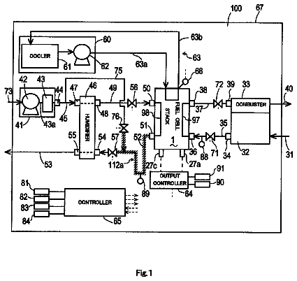
FIG. 1 is a constitution diagram showing the whole constitution of a fuel cell system according to Embodiment 1 of the present invention;
FIG. 2 is a constitution diagram showing the constitution of functional blocks in a control unit 5 of the fuel cell system according to Embodiment 1 of the present invention;
FIG. 3 is a graph diagram showing a relationship between an air blow interval and a cell voltage;
FIG. 4 is a graph diagram showing the properties of a relationship between a fuel gas consumption amount estimated from a power generation current and a theoretical air supply time interval;
FIG. 5 is a flow chart diagram showing an operation procedure of processing to judge the degradation of an electrolyte in a fuel cell stack of the fuel cell system according to Embodiment 1 of the present invention;
FIG. 6 is a graph diagram showing a relationship between an air blow interval and a cell voltage in a case where catalyst activation processing is performed;
FIG. 7 is a flow chart diagram showing an operation procedure of processing to judge the degradation of an electrolyte in a fuel cell stack of a fuel cell system according to Embodiment 2 of the present invention; and
FIG. 8 is a constitution diagram showing a constitution of functional blocks in an FC control unit 52 according to Embodiment 3 of the present invention.
Detailed description
Next, preferable embodiments for performing the present invention will be described in order of Embodiment 1 and Embodiment 2 with reference to the drawings. In the following embodiments, the present invention is applied to a hybrid fuel cell system mounted in an electric car. Moreover, the embodiments are merely the illustration of the configuration of the application of the present invention, and do not limit the present invention.
Embodiment 1
FIG. 1 is a constitution diagram showing the whole constitution of a fuel cell system according to a first embodiment of the present invention.
As shown in FIG. 1, the fuel cell system according to the present embodiment is constituted of a fuel gas supply system 1 which supplies a fuel gas (an anode gas and a hydrogen gas) to a fuel cell 100 described later; a cathode gas supply system 2 which supplies an oxidizing gas (a cathode gas and air) to the fuel cell 100; a power system 4; and a control unit 5 (control means) which performs necessary control. The fuel gas and the oxidizing gas will generically be referred to as a reactant gas.
The fuel cell 100 comprises a stack structure in which a plurality of cells (unitary cells) are stacked. Each cell has a structure in which a power generator referred to as a membrane electrode assembly (MEA) is sandwiched between a pair of separators having passages of the fuel gas, the oxidizing gas and cooling water. The MEA has a structure in which a polymer electrolyte membrane is sandwiched between two electrodes of an anode and a cathode. The anode has a constitution in which a catalyst layer for a fuel pole is provided on a porous support layer, and the cathode has a constitution in which a catalyst layer for an air pole is provided on a porous support layer. Additionally, as the configuration of the fuel cell, a phosphoric acid type, a melted carbonate type or the like can be used. The catalyst layers of these electrodes have a constitution obtained by attaching, for example, platinum particles.
The fuel cell 100 causes the backward reaction of the electrolysis of water, and hydrogen is supplied as the fuel gas from the fuel gas supply system 1 to an anode (cathode) side. Air as the oxidizing gas including oxygen is supplied from the oxidizing gas supply system 2 to a cathode (anode) side. A reaction of formula
occurs on the anode side, and a reaction of formula
occurs on the cathode side, to circulate electrons, thereby allowing a current to flow. H.sub.2.fwdarw.2H.sup.++2e.sup.-
2H.sup.++2e.sup.-+(1/2)O.sub.2.fwdarw.H.sub.2O
The fuel gas supply system 1 comprises a hydrogen tank 10 as a hydrogen gas supply source; a fuel gas supply path 11; a fuel off-gas discharge path 12; and a fuel gas pressure sensor 13 which measures the gas pressure of the hydrogen gas to detect the cross leak of the hydrogen gas. In addition, the fuel gas supply system may comprise a hydrogen pump for circulating the hydrogen gas, and a main valve, a regulation valve, a shutoff valve, a check valve, a gas-liquid separator and the like necessary for the management/control of the hydrogen gas (not shown).
A high pressure hydrogen gas is charged into the hydrogen tank 10. As the hydrogen supply source, in addition to the high pressure hydrogen tank, various sources such as a hydrogen tank using a hydrogen storing alloy, a to hydrogen supply mechanism by a reforming gas, a liquid hydrogen tank and a liquefied fuel tank can be applied. The fuel gas supply path 11 is a piping line which supplies the high pressure hydrogen gas, and may comprise a pressure regulation valve (the regulator) halfway (not shown). In the fuel cell 100, the hydrogen gas supplied from the fuel gas supply path 11 is supplied to the anode side of each unitary cell through a manifold, causes an electrochemical reaction in the anode of the MEA, and is then discharged as a fuel off-gas (a hydrogen off-gas). The fuel off-gas discharge path 12 is a path through which the fuel off-gas discharged from the fuel cell 100 is discharged, and may be provided with a circulation path. The circulation path has a constitution in which the fuel off-gas is again returned to the fuel gas supply path 11 through a check valve or an ejector (not shown).
The oxidizing gas supply system 2 comprises a compressor 20, an oxidizing gas supply path 21 and an oxidizing off-gas discharge path 22. Additionally, the system may comprise a humidifier which controls the humidity of the air as the oxidizing gas, a gas-liquid separator which removes an oxidizing off-gas (an air off-gas), a diluter for mixing the oxidizing off-gas with the fuel off-gas, a muffler and the like, although they are not shown in FIG. 1.
The compressor 20 compresses air taken from an air cleaner or the like based on a control signal C.sub.COMP, and varies an air amount or an air pressure, to supply the air to the cathode side of the fuel cell 100. The air supplied from the oxidizing gas supply path 21 in the fuel cell 100 is supplied to the cathode side of each unitary cell through a manifold in the same manner as in the hydrogen gas, causes an electrochemical reaction in the cathode of the MEA, and is then discharged as the oxidizing off-gas. The oxidizing off-gas discharged from the fuel cell 100 is diluted and discharged together with the fuel off-gas.
The power system 4 comprises a battery 40, a DC-DC converter 41, a traction inverter 42, a traction motor 43, an auxiliary machine inverter 44, a high pressure auxiliary machine 45, a battery computer 46, a current sensor 47, a voltage sensor 48 which measures the output voltage of the fuel cell, a counter flow prevention diode 49 and the like.
The battery 40 is a chargeable/dischargeable secondary cell. As the battery, various types of secondary cells, for example, a nickel-hydrogen battery may be used. Instead of the secondary cell, a chargeable/dischargeable accumulator such as a capacitor may be used. In the battery 40, a plurality of battery units for generating a power at a constant voltage can be stacked and connected in series, to output a high voltage.
The battery computer 46 is provided at an output terminal of the battery 40, and can communicate with a control unit 3. The battery computer 46 monitors the state of charge of the battery 40, keeps an adequate charging range so that the battery is not overcharged nor over-discharged, and notifies the control unit 3, if the battery has a state such as an overcharge state or an over-discharge state.
The DC-DC converter 41 corresponds to power conversion means for raising or lowering the voltage between a primary side and a secondary side based on a control signal C.sub.CONV to circulate a power. For example, the output voltage of the battery 40 on the primary side is raised up to the output voltage of the fuel cell 100 on the secondary side, and the power is supplied to a load device such as the traction motor 43 or the high pressure auxiliary machine 45. On the contrary, the surplus power of the fuel cell 100 or a regenerative power from the load device is lowered on the secondary side, and is passed to charge the battery 40 on the primary side.
The traction inverter 42 converts a direct current into a three-phase alternate current to supply the current to the traction motor 43. The traction motor 43 is, for example, a three-phase motor, and is a main power source for a car in which the fuel cell system is mounted.
The auxiliary machine inverter 44 is direct current-alternate current conversion means for driving the high pressure auxiliary machine 45. The high pressure auxiliary machine 45 comprises various types of motors necessary for the operation of the fuel cell system, for example, the motors for the compressor 20, a hydrogen pump and a cooling system.
The current sensor 47 detects the output current of the fuel cell 100, and outputs a current detection signal Si to the control unit 5. The voltage sensor 48 detects the output voltage of the fuel cell 100, and outputs a voltage detection signal Se to the control unit 5. A cell monitor 101 detects the cell voltage of a part or all of the cells of the fuel cell 100, and outputs a cell voltage detection signal Sc to the control unit 5.
The control unit 5 is constituted of two control units, one of them is an HV control unit 51 which controls hybrid running, and the other control unit is an FC control unit 52 which controls the operation of the fuel cell. Each of the control units comprises a constitution of a multi-purpose computer including a central processing unit (CPU), an RAM, an ROM, an interface circuit and the like, and mutual communication enables the control of the whole system. The HV control unit 51 successively executes a software program stored in an internal ROM or the like, to mainly control the power system 4. In particular, the HV control unit 51 controls power circulation among these elements in view of the generated power of the fuel cell 100, the charge power of the battery 40 and the consumption power of various motors. Additionally, cell voltage lowering prevention processing, high-potential-avoiding processing and a part of catalyst layer activation processing can be executed. Moreover, the FC control unit 52 successively executes the software program stored in the internal ROM or the like to control the whole fuel cell system mainly including the anode gas supply system 1 and the cathode gas supply system 2. Additionally, a part of the activation processing of the catalyst layer can be executed.
FIG. 2 is a constitution diagram showing the constitution of functional blocks in the control unit 5 of the fuel cell system according to the first embodiment of the present invention.
As shown in FIG. 2, the control unit 5 is divided into the HV control unit 51 and the FC control unit 52 as described above. The HV control unit 51 comprises a power system control unit 511, a high-potential-avoiding processing unit 512 and a part of a catalyst activation processing unit 513. The FC control unit 52 comprises a cell voltage lowering prevention processing unit 521, a degradation judgment unit 522 according to the present invention, and a part of the catalyst activation processing unit 513.
The power system control unit 511 is a functional block which controls the whole power circulation in the fuel cell 100, the battery 40, various motors and the like. Detection signals from various sensors are input to determine load distribution between the fuel cell 100 and the battery 40, and the control of the charging into the battery 40 in the case of the supply of the regenerative power or the like is performed.
The high-potential-avoiding processing unit 512 is a functional block which performs the high-potential-avoiding processing. Specifically, the high-potential-avoiding processing unit 512 judges whether or not an output voltage Vfc or a cell voltage Vc of the fuel cell 100 exceeds a predetermined high-potential-avoiding voltage threshold value with reference to the voltage detection signal Se supplied from the voltage sensor 48 and/or the cell voltage detection signal Sc supplied from the cell monitor 101. When the voltage exceeds the high-potential-avoiding voltage threshold value, a control signal SCONV is output to the DC-DC converter 41 to lower a secondary side voltage, that is, the output voltage of the fuel cell 100. Moreover, the high-potential-avoiding processing unit outputs, to the compressor 20, the control signal CCOMOP for supplying air to compensate for the amount of the generated power which increases in accordance with the lowering of the output voltage of the fuel cell.
The catalyst activation processing unit 513 is a functional block which performs catalyst activation processing. Specifically, on predetermined conditions that a low efficiency operation such as an intermittent operation is performed, the catalyst activation processing unit 513 limits the supply of the oxidizing gas and the fuel gas periodically or in a case where it can be judged from the cell voltage Vc or the like that the oxidation of the catalyst of the electrolyte membrane is proceeding. Moreover, the secondary side voltage of the DC-DC converter 41 is gradually lowered to a catalyst activation target voltage, to keep the proceeding state of the electrochemical reaction in the reduction region of the catalyst, thereby activating the catalyst (also referred to as refreshing). The catalyst activation target voltage is kept for a constant time, and then the DC-DC converter 41 is controlled to restore the secondary side voltage to the original voltage. At this time, the compressor 20 is controlled to compensate for the oxidizing gas which runs short owing to the catalyst activation processing, thereby supplying the constant amount of the oxidizing gas for a period of time (this processing will hereinafter be referred to as "air blow").
The cell voltage lowering prevention processing unit 521 is a functional block which performs the cell voltage lowering prevention processing. Specifically, the cell voltage lowering prevention processing unit 521 judges whether or not the cell voltage is below a predetermined minimum lower limit voltage during the intermittent operation with reference to the cell voltage detection signal Sc from the cell monitor 101. Moreover, when the cell voltage is below the minimum lower limit voltage, the compressor 20 is driven for a constant time to supply the constant amount of the oxidizing gas (air blow), thereby raising the cell voltage. The supply of the reactant gas is stopped in principle during the intermittent operation, and the cell voltage lowers when the oxidizing gas runs short with the elapse of the constant time after the air blow, whereby the air blow is required again. That is, the cell voltage lowering prevention processing unit 521 periodically performs the air blow during the intermittent operation.
The degradation judgment unit 522 is a functional block which judges the degradation of the electrolyte membrane of the fuel cell 100 in consideration of both the flow rate of the oxidizing gas supplied during the intermittent operation and the flow rate of the oxidizing gas consumed to maintain the function of the fuel cell 100 according to the present invention. Specifically, the degradation judgment unit 522 comprises a relationship table 523, fuel gas consumption amount estimation means 524, theoretical air supply time interval acquisition means 525, actual air supply time interval measuring means 526 and degradation judgment means 527.
The relationship table 523 is a table which contains a record of a relationship between the consumption amount of the fuel gas (the supply amount of the fuel gas required during the intermittent operation) and the theoretical air supply time interval varying with the increase of the fuel gas consumption amount (hereinafter referred to also as the "theoretical time interval"), and is stored in a storage section of the control unit 5. For example, when the supply amount of the fuel gas is specified by the number of moles and the air supply time interval (the interval of the air blow) can be grasped by the number of seconds, the relationship table 523 regulates a relationship of the number of the seconds, which is the air supply time interval, with respect to the number of the moles of the fuel gas (see FIG. 4).
The fuel gas consumption amount estimation means 524 is a functional block which estimates the fuel gas consumption amount per unit time during the intermittent operation based on an output current Ifc of the fuel cell 100 detected on the basis of the detection signal Si supplied from the current sensor 47. Here, the fuel gas consumption amount estimated by the fuel gas consumption amount estimation means 524 is the whole fuel gas consumption amount estimated from the output current of the fuel cell, and includes both the consumption amount of the fuel gas necessary for the intermittent operation and the consumption amount of the fuel gas which increases during the execution of the high-potential-avoiding processing.
The theoretical air supply time interval acquisition means 525 is a functional block which acquires the theoretical air supply time interval corresponding to the fuel gas consumption amount estimated by the fuel gas consumption amount estimation means 524 with reference to the relationship table 523. The theoretical air supply time interval acquired corresponding to the fuel gas consumption amount reflects the increase of the consumption amount of the oxidizing gas for maintaining the function of the fuel cell in the high-potential-avoiding processing or the like.
The actual air supply time interval measuring means 526 is a functional block which measures the interval of the air blow performed under the control of the cell voltage lowering prevention processing unit 521, that is, the actual air supply time interval (hereinafter referred to also as "the actual time interval"). Here, the actual air supply time interval measuring means 526 compares the time interval with the time interval of the air blow corresponding to the fuel gas consumption amount with the exclusion of the air blow immediately after the end of the catalyst activation processing from the actually executed air blow. This will be described in detail later in Embodiment 2.
The degradation judgment means 527 is a functional block which considers that the actual supply time interval of the air supply measured by the actual air supply time interval measuring means 526 corresponds to the fuel gas consumption amount, and judges whether or not the time interval is shorter than the theoretical air supply time interval acquired by the theoretical air supply time interval acquisition means 525, to judge the degradation of the electrolyte of the fuel cell 100.
(Description of Operation)
Next, the operation of the processing to judge the degradation of the electrolyte of the fuel cell stack will be described in the fuel cell system according to the present embodiment.
FIG. 3 shows a relationship between the interval of the air blow executed by the cell voltage lowering prevention processing and a cell open circuit voltage during the intermittent operation.
As shown in FIG. 3, the fuel cell system sets a minimum lower limit voltage Vth1, below which the cell voltage should not be, for the cell voltage lowering prevention processing. The cell voltage lowering prevention processing unit 521 monitors the cell voltage Vc detected by the cell monitor 101, and executes the air blow for a predetermined time when the cell voltage Vc reaches the minimum lower limit voltage Vth1. When the air blow is executed, the oxidizing gas is supplied to temporarily recover the cell voltage Vc. However, when the oxidizing gas starts running short again after the air blow, the cell voltage Vc starts lowering. When the cell voltage reaches the minimum lower limit voltage Vth1, the air blow is executed again. It is considered that the time interval of the air blow corresponds to the consumption amount of the oxidizing gas necessary for the intermittent operation as long as the oxidizing gas is not excessively consumed to maintain the function of the fuel cell, and the consumption amount of the oxidizing gas also corresponds to the consumption amount of the fuel gas owing to the relationships of the above formulas
to (3). Therefore, when the consumption amount of the fuel gas can be grasped, the supply amount of the fuel gas, that is, the theoretical time interval of the air blow (the theoretical time interval) can be grasped. The fuel gas consumption amount can be calculated from the output current of the fuel cell 100 based on the relationships of the above formulas
to (3). The relationship table 523 contains a record of the theoretical air blow time interval Tc obtained from the supply amount of the oxidizing gas required for the consumption amount of the fuel gas.
The description continues in the full USPTO document.
 Lapsed, fee not paid2 drawings