Cross-reference to related applications
This nonprovisional application claims priority under 35 U.S.C. .sctn.119(a) on Patent Application No. 2012-079116 filed in Japan on Mar. 30, 2012, the entire contents of which are hereby incorporated by reference.
Technical field
The present invention relates to an image recording apparatus in which an image is recorded in a recording medium.
Background
Japanese Patent Application Laid-Open No. 2010-162804 discloses an image forming apparatus in which an image is formed by ejecting ink from nozzles while an ink jet head reciprocates in a scanning direction. The image forming apparatus disclosed in Japanese Patent Application Laid-Open No. 2010-162804 comprises nozzles for black arranged at half the interval of nozzles for color, in which the nozzles for black and the nozzles for color eject ink while the ink jet head reciprocates in the scanning direction and a recording sheet is conveyed by the distance corresponding to the interval of five nozzles for black every time a moving direction of a carriage is inverted, to form an image on the recording sheet.
Summary
A case is considered where an image is formed with the image forming apparatus disclosed in Japanese Patent Application Laid-Open No. 2010-162804 by ejecting black ink and color ink superposed on each other. In Japanese Patent Application Laid-Open No. 2010-162804, both black ink and color ink are ejected when the carriage is moved to either side of the scanning direction. This causes the black ink and the color ink to be ejected in one order when the carriage is moved to the right side but in the opposite order when the carriage is moved to the left side. Thus, the resulting image has a mixture of a portion where the image is formed by ejecting color ink after black ink and a portion where the image is formed by ejecting black ink after color ink.
In the case of ejecting black ink and color ink by superposing one on the other, the first-ejected ink spreads out widely on a recording medium because it is ejected on the recording medium where no ink had been ejected. On the contrary, the later-ejected ink does not spread as widely as the first-ejected ink because it is ejected on the recording medium where ink had already been ejected.
Accordingly, in the image formed with the image forming apparatus disclosed in Japanese Patent Application Laid-Open No. 2010-162804, black ink stands out at the portion where the image is formed by ejecting color ink after black ink is ejected, whereas color ink stands out at the portion where the image is formed by ejecting black ink after color ink is ejected. Thus, the image would have non-uniformity between the portion where the black ink stands out and the portion where the color ink stands out, leading to degradation in image quality.
As a method of controlling such that the order of ejecting black ink and color ink is maintained irrespective of portions of a recording medium in the image forming apparatus disclosed in Japanese Patent Application Laid-Open No. 2010-162804, black ink and color ink may be ejected from nozzles only when the carriage is moved to either one of the right side and the left side in the scanning direction. It is alternatively considered that, in the image forming apparatus disclosed in Japanese Patent Application Laid-Open No. 2010-162804, only black ink is ejected from nozzles when the carriage is moved to one of the right side and the left side in the scanning direction, whereas only color ink is ejected from nozzles when the carriage is moved to the side opposite from the above-described one of the right side and the left side in the scanning direction.
In the cases as described above, however, the number of movements of the carriage necessary to record an image increases because no ink is ejected from nozzles when the carriage is moved to the side opposite from the above-described one of the right side and the left side in the scanning direction, or because only one of the black or color ink is ejected every time when the carriage is moved to the right side or to the left side, which increases time required for recording the image.
To solve such a problem, it is an object to provide an image recording apparatus which is capable of recording an image in a significantly short period of time while eliminating non-uniformity between different portions in the recorded image due to a difference in the order of ejecting ink.
An image recording apparatus according to a first aspect is an image recording apparatus, comprising: an ink jet head ejecting ink from a plurality of nozzles; a carriage equipped with the ink jet head and reciprocating in a predetermined moving direction; a conveyance mechanism conveying a recording medium to which ink is ejected from the nozzles in a conveying direction perpendicular to the moving direction; and a control section controlling operations of the ink jet head, the carriage and the conveyance mechanism, wherein the ink jet head is provided with: a plurality of first nozzles aligned with an interval D1 in the conveying direction and ejecting first ink; and a plurality of second nozzles positioned on one side in the moving direction with respect to the plurality of first nozzles and aligned with an interval nD1 (n is an integer larger than 1) in the conveying direction, and ejecting second ink of a type different from the first ink, the control section repeatedly executes a unit recording operation in which the carriage is moved alternately to the one side and to another side in the moving direction for n times, while ink is ejected from at least one of the plurality of first nozzles and the plurality of second nozzles and the conveyance mechanism conveys a recording medium in the conveying direction by a length of (1+mn)D1 (m is 0 or an arbitrary natural number) every time the moving direction of the carriage is inverted, the control section causes both the plurality of first nozzles and the plurality of second nozzles to eject ink at first movement of the carriage in which a direction of the first movement of the carriage is toward the another side or at last movement of the carriage in which a direction of the last movement of the carriage is toward the one side among n movements of the carriage, and the control section causes only the plurality of second nozzles to eject ink at movement of the carriage except for the first movement or the last movement among n movements of the carriage.
According to the first aspect, when ink is ejected from both the plurality of first nozzles and the plurality of second nozzles at the first movement of the carriage in which the direction of the first movement of the carriage is toward another side as a unit recording operation, any portion of an image to be recorded to a recording medium is recorded by ejecting the second ink after the first ink is ejected. When, on the other hand, ink is ejected from both the plurality of first nozzles and the plurality of second nozzles at the last movement of the carriage in which the direction of the last movement of the carriage is toward one side as a unit recording operation, any portion of an image to be recorded to a recording medium is recorded by ejecting the first ink after the second ink is ejected. This can prevent non-uniformity from occurring between regions in an image to be recorded to a recording medium.
Moreover, in the unit recording operation, at least one of the first nozzle and the second nozzle ejects ink when the carriage is moved to each of the directions, and both the first and second nozzles further eject ink at the first or the last movement of the carriage. This can significantly reduce the number of movements of the carriage necessary for recording an image, thereby preventing delay in recording of the image.
According to the first aspect, non-uniformity between regions in the image to be recorded on a recording medium caused by the difference in the order of ejecting the first ink and the second ink can be avoided. This can also largely reduce the number of movements of the carriage necessary for recording an image, thereby preventing delay in recording of the image.
The above and further objects and features will more fully be apparent from the following detailed description with accompanying drawings.
Brief description of the several views of the drawings
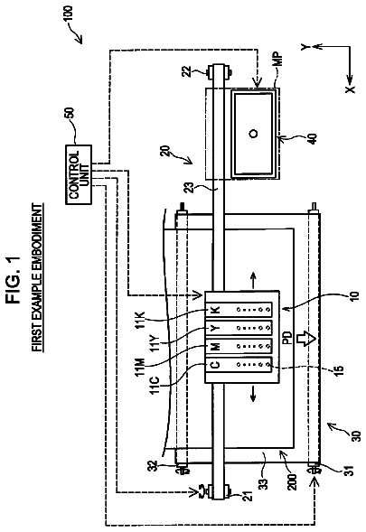
FIG. 1 is a schematic configuration diagram of a printer 1 according to an embodiment,
FIG. 2 is a diagram illustrating a positional relationship of nozzles at an ink jet head shown in FIG. 1,
FIG. 3 is a block diagram illustrating a hardware configuration of the printer 1 according to the embodiment,
FIG. 4 is a diagram illustrating nozzles for ejecting ink and positions where ink is ejected when an image is recorded in the first recording mode,
FIG. 5 is a diagram illustrating nozzles for ejecting ink and positions where ink is ejected when an image is recorded in the second recording mode,
FIG. 6 is a diagram illustrating nozzles for ejecting ink and positions where ink is ejected when an image is recorded in the third recording mode,
FIG. 7 is a flowchart illustrating a procedure of print processing,
FIG. 8 is a diagram corresponding to FIG. 4 and illustrating one modification, and
FIG. 9 is a diagram corresponding to FIG. 5 and illustrating one modification.
Detailed description
A preferred embodiment will be described below.
As shown in FIG. 1, the printer 1 according to the present embodiment comprises a carriage 2, an ink jet head 3, a sheet conveying roller 4 and the like. Moreover, the operation of the printer 1 is controlled by a control device 50.
The carriage 2 reciprocates in a scanning direction along two guide rails 5. Note that the right side and the left side in the scanning direction are defined as shown in FIG. 1 in the description below. The ink jet head 3 is provided with three black head units 11a to 11c, and three color head units 12a to 12c.
As illustrated in FIG. 2, the three black head units 11a to 11c are arranged in the scanning direction and respectively include a plurality of black nozzles 15 aligned at an interval Kn in a conveying direction perpendicular to the scanning direction. Moreover, the black head unit 11b is arranged at a position displaced from the black head 11a toward an upper stream in the conveying direction by an interval Kb which is a third of the interval Kn (=Kn/3). The black head unit 11c is arranged at a position displaced from the black head unit 11b toward the upper stream in the conveying direction by the interval Kb. Thus, at the ink jet head 3, the black nozzles 15 for the adjacent black head units 11a to 11c are spaced apart from one another by the interval Kb in the conveying direction.
In the present embodiment, as described above, the three black head units 11a to 11c each including black nozzles 15 aligned at the interval Kn are spaced apart from one another by the interval Kb in the conveying direction, so that the black nozzles 15 are spaced apart from one another by the interval Kb. It is, however, also possible to provide one black head unit with the black nozzles 15 aligned at the interval Kb instead of the three black head units 11a to 11c.
The three color head units 12a to 12c are aligned in the scanning direction and respectively include a plurality of color nozzles 16 aligned at the interval Kn in the conveying direction perpendicular to the scanning direction. Moreover, the three color head units 12a to 12c are not displaced from one another in the conveying direction, so that the color nozzles 16 of the three color head units 12a to 12c are positioned at the same positions as the black nozzles 15 of the black head unit 11c with respect to the conveying direction.
Furthermore, as shown in FIG. 1, the ink jet head 3 is connected to four ink cartridges 14 through four tubes 13. The four ink cartridges 14 have ink of black, yellow, cyan and magenta stored therein in this order from the right side of the scanning direction. The ink of four colors is supplied to the ink jet head 3 through the tubes 13.
The ink jet head 3 ejects the four-color ink supplied from the ink cartridges 14. More specifically, the black ink is ejected from the black nozzles 15 of the black head units 11a to 11c, while the ink of yellow, cyan and magenta is ejected from the color nozzles 16 of the color head units 12a to 12c, respectively.
The sheet conveying roller 4 conveys a recording sheet P in the conveying direction. In the printer 1, the carriage 2 is moved to the right side or to the left side in the scanning direction while scanning in which ink is ejected from the ink jet head 3 mounted on the carriage 2 is repeated, and the recording sheet P is conveyed with the sheet conveying roller 4 in the conveying direction by a predetermined amount every time the moving direction of the carriage 2 is inverted, to record an image on the recording sheet P.
Next, a hardware configuration of the printer 1 will be described with reference to FIG. 3. As shown in FIG. 3, the printer 1 comprises a control device 50, a driver IC 61, a carriage motor 62, a conveyance motor 63, an ink jet head 3, a receiving device 64, a reading device 65 and an operation panel 66.
The receiving device 64 may be an interface for receiving various types of data transmitted from an external device 71 such as a PC to the printer 1. More specifically, a well-known network card, a USB device controller or the like may be used. The reading device 65 may be a controller for reading various types of data stored in an external memory 72 such as a portable storage like a memory card or an internal memory of a digital camera. More specifically, a well-known memory controller, a USB host controller or the like may be used. The operation panel 66 includes a display and various types of operation buttons for operation by the user. The user can operate the operation panel 66 to input various instructions to the printer 1.
The control device 50 includes various types of control circuits including a CPU (Central Processing Unit), a ROM (Read Only Memory), a RAM (Random Access Memory), ASIC and the like. The control device 50 performs various types of processing such as recording control processing, image data acquisition processing, mode information acquisition processing, determination processing and the like in accordance with various types of programs stored in a memory such as ROM or RAM.
The recording control processing is for controlling the operations of the driver IC 61 for driving the ink jet head 3, the carriage motor 62 for moving the carriage 2, the conveyance motor 63 for driving the sheet conveying roller 4 and the like when an image is recorded at the printer 1. The control device 50 controls the driver IC 61, the carriage motor 62, the conveyance motor 63 and the like to selectively record an image in any one of the first to third recording modes, which will be described later.
The image data acquisition processing is for acquiring image data transmitted from the external device 71 such as a PC to the printer 1. The control device 50 may also acquire image data through the receiving device 64 described above. The external device 71 such as a PC creates image data which can be printed at the printer 1 when, for example, the user gives an instruction to print a desired electronic file, and transmits the created image data to the printer 1. Note that the image data may be data described in a page descriptive language or may be data of an image file in a predetermined format such as JPEG which can be decrypted by the printer 1.
The mode information acquisition processing is for acquiring mode information indicating which one of the first to third recording modes described later is set to record an image on a recording sheet P. The control device 50 may acquire the mode information through the receiving device 64 described above. It is noted that the mode information in the present embodiment may be data created by the printer driver of the external device 71 when an instruction for printing is given by the external device 71 such as a PC. The external device 71 transmits the mode information along with the image data described above to the printer 1. Note that the mode information acquired by the control device 50 may be data described in a page descriptive language or may be data described at the header of an image file in a predetermined format such as JPEG.
The printer driver in the external device 71 may generate mode information, indicating which recording mode is set for printing, in accordance with various types of print setting and a file format of an original electronic file. For example, it may be so configured that the user can select a desired recording mode among the first to third recording modes with a GUI of the printer driver and that the printer driver generates mode information based on the selected recording mode. The user may directly set a desired recording mode among the first to third recording modes.
Moreover, instead of the user directly setting any one of the first to the third recording modes, the printer driver may generate mode information indicating any one of the first to third recording modes based on print setting of another item input by the user. For example, it may be configured that "monochrome/color setting" can be selected on the GUI of the printer driver. In the item of "monochrome/color setting," either one of "monochrome printing" or "color printing" may be selected for print setting. When "monochrome printing" is being set, the printer driver may generate mode information indicating the third recording mode. When, on the other hand, "color printing" is being set, the printer driver may generate mode information indicating one of the first recording mode and the second recording mode based on the file format of an original electronic file designated for printing. More specifically, in the case of forming a file such as spreadsheet software or word processing software that uses characters, mode information indicating the first recording mode may be generated. If, on the other hand, the file format of the original electronic file is an image file such as TIFF or GIF, mode information indicating the second recording mode may be generated.
The determination processing is to determine which one of the first to third recording modes described later is set to record an image on a recording sheet P in the printer 1 based on the mode information acquired at the mode information acquisition processing. The details of the determination processing will be described later.
Recording of an image in the first to third recording modes as described above will now be described. The first recording mode is to record a color image by ejecting black ink and color ink superposed on one another on a recording sheet P. The left side view in FIG. 4 schematically shows a positional relationship of black nozzles 15 and color nozzles 16 in each scanning operation of the first recording mode as well as the black nozzles 15 and color nozzles 16 ejecting ink. In the left side view of FIG. 4, the circled "B" and "C" correspond to the black nozzles 15 for the three black head units 11a to 11c and to the color nozzles 16 for the three color head units 12a to 12c, respectively. Each of the numbers 1 through 7 at the upper side on the left side view of FIG. 4 indicates which number of times the scanning corresponds to. The arrow shown below each of the numbers indicates a moving direction of the carriage 2 in each scanning operation. Moreover, in the left side view of FIG. 4, the black nozzles 15 and color nozzles 16 ejecting ink at each scanning are indicated by solid lines, while the black nozzles 15 and color nozzles 16 not ejecting ink are indicated by broken lines.
The right side view in FIG. 4 schematically shows a eject state of ink when an image is recorded in the first recording mode. In the right side view of FIG. 4, the circled "B" and "C" correspond to ink ejected from the black nozzles 15 and ink ejected from the color nozzles 16, respectively. Moreover, each of the numbers described alongside "B" and "C" indicates which number of times the scanning corresponds to when ink is ejected. Furthermore, each of the numbers 1 through 7 at the lower side of the right side view in FIG. 4 indicates the number of times the scanning is performed immediately before the ink is ejected. In addition, a position where ink is ejected, i.e. ejection position, in each scanning is indicated by the solid line whereas a position where ink is ejected prior to that is indicated by a broken line. In the right side view of FIG. 4, though the ejection position for black ink and the ejection position for color ink are illustrated side by side in the scanning direction, the black ink and color ink are ejected so as to be superposed on each other at least on one portion of a recorded image.
Though, at the printer 1, in practice, a recording sheet P is conveyed in the conveying direction without a change in the position of the ink jet head 3 in the conveying direction, the position of the recording sheet P is fixed in FIG. 4 to show the position of the ink jet head 3 on the basis of the recording sheet in order to clearly indicate the position where ink is ejected on the recording sheet P. Moreover, FIG. 4 shows an example where an image is recorded in a region R in which eighteen dots are aligned in the conveying direction of the recording sheet P. Furthermore, regions R1 through R6 shown in FIG. 4 are formed by dividing the region R into six regions in the conveying direction, and in each of the regions R1 through R6, three dots are aligned in the conveying direction.
In the first recording mode, the first scanning is executed in which ink is ejected from the black nozzles 15 and the color nozzles 16 while moving the carriage 2 to the left side. Thereafter, a recording sheet P is conveyed in the conveying direction by the same length as the interval Kb. Subsequently, the second scanning is executed in which ink is ejected only from the color nozzles 16 while the carriage 2 is moved to the right side. Thereafter, the recording sheet P is conveyed by the same length as the interval Kb. Subsequently, the third scanning is executed in which ink is ejected only from the color nozzles 16 while moving the carriage 2 to the left side. In the first to third scanning as described above, ink is ejected only from the black nozzles 15 and color nozzles 16 set in the regions R1 through R3 among the black nozzles 15 and the color nozzles 16. Accordingly, the first unit recording operation including the series of scanning operations allows the printer 1 to record an image in the regions R1 through R3 with a resolution corresponding to the interval Kb of the black nozzles 15.
Next, as the fourth scanning, blank scanning is executed in which the carriage 2 is moved to the right side at a speed higher than that in the first to third scanning operations without ejecting ink from the black nozzles 15 and color nozzles 16. Thereafter, at the position where the ink jet head 3 is not opposed to the recording sheet P, flushing is executed in which ink is ejected from the black nozzles 15. Moreover, while the blank scanning and the subsequent flushing are executed, the recording sheet P is conveyed by the length of 7 Kb which is seven times the interval Kb, i.e. by the length of Kb+2Kn which is obtained by adding a value corresponding to twice the interval Kn to the interval Kb.
Subsequently, the first unit recording operation is executed again. That is, the fifth through seventh scanning operations are executed as in the first through third scanning operations, and the recording sheet P is conveyed by the same interval as the interval Kb after the fifth and sixth scanning operations. Note that, in the fifth through seventh scanning operations, ink is ejected only from the black nozzles 15 and color nozzles 16 that are set in the regions R4 through R6. This allows the printer 1 to record an image with a resolution corresponding to the interval Kb of the black nozzles 15 in the regions R4 through R6.
It is noted that, when an image is recorded in a region longer than the region shown in FIG. 4 in the conveying direction, thereafter, the blank scanning and the subsequent flushing are further executed while the recording sheet P is conveyed by the length 7 Kb during the blank scanning and flushing. From then on, the first unit recording operation, blank scanning, flushing, and conveyance of the recording sheet P during the blank scanning and flushing are repeatedly executed in accordance with the length related to the conveying direction of the region in which an image is to be recorded.
The second recording mode is different from the first recording mode and is for recording a color image by ejecting black ink and color ink superposed on one another on a recording sheet P. FIG. 5 is a diagram corresponding to FIG. 4 in the second recording mode.
In the second recording mode, the first scanning is executed in which ink is ejected only from the color nozzles 16 while moving the carriage 2 to the right side, and thereafter the recording sheet P is conveyed by the same length as the interval Kb in the conveying direction. Subsequently, the second scanning is executed in which ink is ejected only from the color nozzles 16 while moving the carriage 2 to the left side, and thereafter the recording sheet P is conveyed by the same length as the interval Kb. Moreover, while the recording sheet P is being conveyed, flushing, in which ink is ejected from the black nozzles 15, is executed at a position where the ink jet head 3 is not opposed to the recording sheet P. Subsequently, the third scanning is executed in which ink is ejected from both the black nozzles 15 and color nozzles 16 while moving the carriage 2 to the right side. In the first to third scanning operations as described above, ink is ejected only from the black nozzles 15 and color nozzles 16 that are set in the regions R1 through R3 among the black nozzles 15 and color nozzles 16. Accordingly, the second unit recording operation including the series of scanning operations allows the printer 1 to record an image in the regions R1 through R3 with a resolution corresponding to the interval Kb of the black nozzles 15.
Next, as the fourth scanning, blank scanning is executed in which the carriage 2 is moved to the right side at a speed higher than that in the first to third scanning operations without ejecting ink from the black nozzles 15 and color nozzles 16. During that time, the recording sheet P is conveyed by the length of 7 Kb which is seven times the interval Kb.
Subsequently, the second unit recording operation is executed again. That is, the fifth through seventh scanning operations are executed as in the first through third scanning operations, and the recording sheet P is conveyed by the same interval as the interval Kb after the fifth and sixth scanning operations. Moreover, after the sixth scanning and before the seventh scanning, flushing is executed. Note that, in the fifth through seventh scanning operations, ink is ejected only from the black nozzles 15 and color nozzles 16 that are set in the regions R4 through R6. This allows the printer 1 to record an image with a resolution corresponding to the interval Kb of the black nozzles 15 in the regions R4 through R6.
Note that, when an image is recorded in a region longer than the region shown in FIG. 5 in the conveying direction, blank scanning is further executed while the recording sheet P is conveyed by the length of 7 Kb. From then on, the second unit recording operation, blank scanning and conveyance of the recording sheet P during the blank scanning are repeatedly executed in accordance with the length related to the conveying direction of the region in which an image is recorded, to record an image on the recording sheet P.
The third recording mode is for recording a monochrome image by using only black ink. FIG. 6 is a diagram corresponding to FIG. 4 in the third recording mode.
In the third recording mode, the first scanning is executed in which ink is ejected from the black nozzles 15 while moving the carriage 2 to the right side. Note that, in the first scanning, ink is ejected only from the black nozzles 15 set in the regions R1 through R3 in relation to the conveying direction.
Next, the recording sheet P is conveyed in the conveying direction by the length of a row of black nozzles 15, i.e. by the lengths of 12 Kb which is twelfth times the interval Kb. Subsequently, the second scanning is executed in which ink is ejected from the black nozzles 15 while moving the carriage 2 to the left side. In the second scanning, ink is ejected only from the black nozzles 15 that are set in the regions R4 through R6 in relation to the conveying direction.
By thus recording an image, the first scanning allows the printer 1 to record a monochrome image in the regions R1 through R3 with a resolution corresponding to the interval Kb of the black nozzles 15 in relation to the conveying direction. Furthermore, the second scanning allows the printer 1 to record a monochrome image in the regions R4 through R6 with a resolution corresponding to the interval Kb of the black nozzles 15 in relation to the conveying direction. That is, the monochrome image can be recorded at a speed higher than that in the first or second recording mode and with the same resolution as that in the first or second recording mode.
It is noted that, when an image is recorded in a region longer in the conveying direction than the region R shown in FIG. 6, the above-described scanning and conveying of the recording sheet P are alternately executed for a number of times corresponding to the length of a region in which an image is to be recorded.
While an image can selectively be recorded at any one of the first to third recording modes, an image formed by ejecting black ink and color ink superposed on one another is recorded both in the first recording mode and the second recording mode. The difference between the quality of an image recorded in the first recording mode and the quality of an image recorded in the second recording mode will be described.
When an image is recorded in the first recording mode, ink is ejected from both the black nozzles 15 and color nozzles 16 at the first scanning in each first unit recording operation, and then ink is ejected only from the color nozzles 16 in the subsequent scanning. Moreover, since the black nozzles 15 are positioned on the left side of the carriage 2 and the carriage 2 moves to the left side in the first scanning, black ink is first ejected and then color ink is ejected at the first scanning in the first unit recording operation. In the first unit recording operation, therefore, black ink is first ejected on the recording sheet P on which no ink have been ejected and thereafter color ink is ejected on the recording sheet P on which the black ink have already been ejected.
Thus, at a portion on the recording sheet P where black ink and color ink are superposed on each other, the black ink is ejected on the recording sheet P which has no ink ejected thereon, and spreads out widely over the recording sheet P. On the other hand, color ink is ejected on the recording sheet P on which black ink has already been ejected, so that it does not spread as widely as the black ink on the recording sheet P. When, therefore, an image is recorded in the first recording mode, an image with black ink standing out is recorded.
When, on the other hand, an image is recorded in the second recording mode, in each second unit recording operation, ink is ejected only from the color nozzles 16 at scanning other than the last scanning, and thereafter, ink is ejected from both the black nozzles 15 and color nozzles 16 in the last scanning. Furthermore, since the black nozzles 15 are positioned on the left side of the carriage 2 and the carriage 2 moves to the right side in the last scanning, color ink is first ejected and then black ink is ejected in the last scanning in the second unit recording operation. In each second unit recording operation, therefore, color ink is first ejected on the recording sheet P with no ink being ejected and thereafter black ink is ejected on the recording sheet P on which color ink has already been ejected.
Thus, at a portion on the recording sheet P where black ink and color ink are superposed on each other, the color ink is ejected on the recording sheet P which has no ink ejected thereon, and spreads out widely over the recording sheet P. On the other hand, black ink is ejected on the recording sheet P on which color ink has already been ejected, so that it does not spread as widely as the color ink on the recording sheet P. When, therefore, an image is recorded in the second recording mode, an image with color ink standing out is recorded.
Furthermore, an image recorded in the first recording mode is formed by ejecting color ink after ejecting black ink at any portion. On the other hand, an image recorded in the second recording mode is formed by ejecting black ink after ejecting color ink at any portion. Thus, an image recorded in the first recording mode or the second recording mode will not have a mixture of a portion in which black ink stands out which is recorded by first ejecting black ink and then ejecting color ink and a portion in which color ink stands out which is recorded by first ejecting color ink and then ejecting black ink. Hence, non-uniformity between portions can be prevented from occurring in a recorded image.
As an image recording method that can prevent non-uniformity due to the difference between the order of ejecting black ink and the order of ejecting color ink from occurring between portions in a recorded image, other than the image recording method using the first and second recording modes as described above, for example, such a method may be considered that both black ink and color ink are ejected only when a carriage is moved to either one of the right and left sides in the scanning direction. With this method, however, ink will not be ejected from any one of the black nozzles 15 and color nozzles 16 at half the number of times for the repeatedly executed scanning operations. This increases the number of times the carriage 2 is required to move for recording an image, which further increases time required for recording the image.
Another possible method is to eject only black ink when a carriage is moved to one of the right and left sides in the scanning direction and to eject only color ink when the carriage 2 is moved to the direction opposite from the above. In this case, however, ink is ejected only from one of the black nozzles 15 and color nozzles 16 in each of the scanning operations. This increases the number of times the carriage 2 is required to move for recording an image, which further increases time required for recording the image.
In the case of the present embodiment, on the other hand, ink is ejected from the color nozzles 16 in each of the scanning operations in the first and second unit recording operations. Furthermore, in the first unit recording operation, ink is ejected from both the black nozzles 15 and color nozzles 16 in the first scanning, whereas, in the second unit recording operation, ink is ejected from both the black nozzles 15 and color nozzles 16 in the last scanning. Thus, the number of times the carriage 2 is required to move for recording an image can be reduced compared to the cases as described above. An image can, therefore, be recorded in a significantly short period of time.
Moreover, in the first and second unit recording operations, ink in the color nozzles 16 is not easily dried because ink is ejected from the color nozzles 16 at all the three scanning operations. On the other hand, ink is ejected from the black nozzles 15 at only one of the three scanning operations. Thus, ink in the black nozzles 15 may be dried by the time the ink is to be ejected next from the black nozzles 15 after ink has been ejected from the block nozzles 15, possibly preventing the black nozzles 15 from normally ejecting ink.
In the present embodiment, flushing is executed after the first unit recording operation, before the subsequent first unit recording operation and immediately before the last scanning in the second unit recording operation. Thus, dryness of ink in the black nozzles 15 is eliminated, allowing the black nozzles 15 to normally eject ink in the first and second unit recording operations.
Moreover, when the color nozzles 16 are aligned with an interval which is three times the interval of the black nozzles 15 as in the present embodiment, three scanning operations are executed in the first and second unit recording operations. Thus, the carriage 2 moves in the same direction both in the first and last scanning operations. In the present embodiment, therefore, blank scanning is executed after the first and second unit recording operations and before the subsequent first and second unit recording operations, so that the first and second unit recording operations can be executed in series. Furthermore, as the moving speed of the carriage 2 in the blank scanning is made faster than that of the carriage 2 at scanning in the first or second unit recording operation, the time required for recording an image can be shortened.
The printer 1 according to the present embodiment records an image in any one of the first to third recording modes as described above. The operation of the control device 50 when an instruction for recording is received from the external device 71 will now be described with reference to FIG. 7.
When the receiving device 64 receives an instruction for recording image data, the control device 50 starts print processing as shown in FIG. 7. When the print processing is started, the control device 50 performs image data acquisition processing and mode information acquisition processing (S101). After acquiring image data by the image data acquisition processing and mode information by the mode information acquisition processing, the control device 50 performs determination processing (S102). After determining which recording mode is set to record image data in the determination processing, the control device 50 performs record control processing based on the recording mode determined at S102 (S103). It is noted that, when more than one pieces of image data are divided to be received in response to one printing instruction, acquisition of the subsequent image data and recording of the image data are repeatedly executed at S103.
In the present embodiment, an image can be recorded in a desired one of the first to third recording modes. In the third recording mode, a monochrome image can promptly be recorded with a high resolution. In the first recording mode, on the other hand, visibility of a character and the like can be increased when an image including a character and the like is recorded as a color image. This is advantageous when, for example, an image to be recorded includes a table with a background color and printing is performed for a file used in spreadsheet software or the like which is assumed to preferably have high visibility for characters by highlighting characters in the table. In the second recording mode, on the other hand, when the duty of jetted ink is high, such as when an acquired file format is for photograph, black nozzles can be prevented from drying and thus a clear image can be recorded.
The description continues in the full USPTO document.
 Lapsed, fee not paid4 drawings