Patent Yard Sign in
Lapsed, fee not paid

Radiant liquid heating container

US 8,726,798 B2 · Assignee: Thermodyne Foodservice Products, Inc. · Inventors: Tippmann, Jr.; Vincent Paul et al.

USPTO PDF

Overview

Sheet 1 of 4 from the published document. All sheets in the USPTO PDF

Abstract From the patent

A radiant liquid heating device includes a container for holding a liquid. The container includes an opening for dispensing the fluid and a closed bottom. A base member is mounted relative to the closed bottom. The base member is spaced a predetermined distance relative to the closed bottom to provide an air gap there between. The base member is exposed to a heat source wherein the base member shields the bottom of the container from being in direct contact with the heat source to provide a source of radiant heat for maintaining a liquid disposed within the container at a predetermined temperature.

Why it's free to use

  • The USPTO Official Gazette of July 14, 2026 lists it as expired on May 20, 2026 for an unpaid maintenance fee.
  • It isn't on any reinstatement notice published since.
  • Its 2 US relatives have also lapsed, expired or never issued.
  • We check US rights only. Check foreign counterparts before selling abroad.
FiledApril 17, 2012
GrantedMay 20, 2014
Expired (fee)May 20, 2026
Application number13/449020
Classification (CPC)A47J36/26
Length19 claims · 8 pages

Drawings 4

All 4 drawing sheets from the published document, cropped to the drawing.

Figures as described

  • FIG. 1 is a perspective view of a container for heating a liquid
  • FIG. 2 is a perspective view of a base member that is formed to fit the bottom of the container illustrated in FIG. 1
  • FIG. 3 is a perspective view of the base member with a dark surface coating the interior of the base member
  • FIG. 4 is an exploded view illustrating the container being mounted on the base member
  • FIG. 5 is a perspective view illustrating the container with the base member being secured relative thereto
  • FIG. 6 is a cross-sectional view of the container and the base member illustrating the gap that is formed between the bottom of the container and the base member
  • FIG. 7 is a cross-sectional view of a metal container with a base member illustrating the gap that is formed between the bottom of the container and the base member

Claims 19 total, 1 independent

What the patent claimed, word for word. All of it is now free to use.

  1. 1
    Independent claimA radiant liquid heating container comprising: an enclosure adapted to hold a liquid; said enclosure includes a closed bottom, an outer portion and an opening for adding or extracting said liquid; a base shell including a bottom member and an outer circumferential surface projecting upwardly from the bottom member a predetermined distance to a top portion; wherein said base shell has a higher curvature than a curvature of said closed bottom of said enclosure, in a perpendicular direction with respect to a plane of the bottom member of said base shell, forming a continuous air gap between said bottom member of said base shell and said bottom of said enclosure without any point contact between the curvature of the base shell and the bottom of the enclosure; said base shell and said enclosure intersect each other at the top of said base shell wherein the outer circumferential surface projecting upwardly a predetermined distance from the bottom member of the base shell extends upwardly the predetermined distance on the outer portion of the enclosure; wherein said continuous air gap is formed between said bottom member of said base shell and said bottom of said enclosure without any point contact between the curvature of the base shell and the bottom of the enclosure and said continuous air gap is formed between the outer circumferential surface projecting upwardly the predetermined distance and the outer portion of said enclosure without any point contact between the outer circumferential surface projecting upwardly the predetermined distance and the outer portion of the enclosure and said top portion of said base shell is sealed at the point of intersection of the top portion of said base shell and said outer portion of the enclosure with a heat resistant material to avoid point contact of said base shell with said enclosure to avoid spot heating of a liquid within said enclosure by providing the continuous air gap between the bottom member of the base shell and the bottom of said enclosure without any point contact between the curvature of the base shell and the bottom of the enclosure and the continuous air gap between the outer circumferential surface projecting upwardly the predetermined distance and the outer portion of said enclosure without any point contact between the outer circumferential surface projecting upwardly the predetermined distance and the outer portion of the enclosure.
  2. 2
    The radiant liquid heating container as recited in claim 1, wherein said base shell is made of metal.
  3. 3
    The radiant liquid heating container as recited in claim 1, wherein said base shell is made of aluminum.
  4. 4
    The radiant liquid heating container as recited in claim 1, wherein said enclosure is made of glass.
  5. 5
    The radiant liquid heating container as recited in claim 1, wherein interior surface of said base shell is coated with a non-reflecting material.
  6. 6
    The radiant liquid heating container as recited in claim 1, wherein interior surface of said base shell is coated with black paint.
  7. 7
    The radiant liquid heating container as recited in claim 1, wherein said seal is made of plastic.
  8. 8
    The radiant liquid heating container as recited in claim 1, wherein said seal is made of silicone.
  9. 9
    The radiant liquid heating container as recited in claim 1, wherein said enclosure is made of metal.
  10. 10
    The radiant liquid heating container as recited in claim 1, wherein said liquid is coffee.
  11. 11
    The radiant liquid heating container as recited in claim 1, wherein said base shell has a circular cross section.
  12. 12
    The radiant liquid heating container as recited in claim 1, wherein said base shell is placed between a heat source and said bottom of said enclosure.
  13. 13
    The radiant liquid heating container as recited in claim 1, wherein interior surface of said base shell is coated with a dark material.
  14. 14
    The radiant liquid heating container as recited in claim 1, wherein said enclosure has a circular cross section.
  15. 15
    The radiant liquid heating container as recited in claim 1, wherein said handle is attached or affixed to top of said enclosure.
  16. 16
    The radiant liquid heating container as recited in claim 1, wherein said liquid's temperature is held at a constant temperature.
  17. 17
    The radiant liquid heating container as recited in claim 1, wherein said liquid is substantially heated through radiant heat.
  18. 18
    The radiant liquid heating container as recited in claim 1, wherein said liquid's temperature is held at a predetermined temperature.
  19. 19
    The radiant liquid heating container as recited in claim 1, said liquid heating container comprises one or more spacers.

Claim map

Independent claims stand on their own. The others add detail to the claim they name.

Description

Background of the invention

1. Field of the invention

The present invention relates to a radiant liquid heating container wherein a base member is mounted relative to the bottom of the container with a predetermined space providing an air gap between the container and the base for maintaining a liquid disposed within the container at a predetermined temperature.

2. Description of Background Art

Hithertofore, a container for maintaining a liquid at a predetermined temperature is normally exposed directly to a heat source. After the liquid is heated on the heat source for a certain period of time, the liquid in the container may be burned by the direct contact of the container relative to the heat source. This is a particular problem with respect to coffee that is brewed and thereafter exposed directly to a heat source. The heat source makes point contact with the container to burn certain portions of the coffee.

More specifically, a liquid product, such as coffee, is maintained in a heated condition by placing the container holding the liquid directly on a heat source, such as a burner. Normally, three points of contact are made between the container and the burner for conducting the heat of the burner to the container. At the points of contact with the burner, the container is heated to a very high temperature that results in a burning of the liquid within the container. When coffee is disposed in the container, the coffee is burned and the liquid within the container is boiled off to produce a coffee product that is not fit for consumption.

In addition, a thermos may be used for storing a heated liquid. However, with time the liquid within the thermos will cool and thus become unsuitable for consumption.

Summary and objects of the invention

It is an object of an embodiment of the present invention to provide a radiant heater for maintaining a liquid within a container at a predetermined temperature without adversely affecting the taste of the liquid.

It is another object of an embodiment of the present invention to provide a radiant heater for maintaining a liquid within a container at a predetermined temperature by displacing the container to form a gap between the container and a base member for heating the container by use of radiant heat while eliminating the point contact between the container and the burner.

These and other objects of the invention are achieved by providing a radiant liquid heating container that includes a container for holding a fluid with an opening for dispensing the fluid and a closed bottom. A base member is mounted relative to the closed bottom. The base member is spaced a predetermined distance relative to the closed bottom to provide an air gap there between. The base member is exposed to a heat source wherein the base member shields the bottom of the container from being in direct contact with the heat source to provide a source of radiant heat for maintaining a liquid disposed within the container at a predetermined temperature.

Further scope of applicability of the present invention will become apparent from the detailed description given hereinafter. However, it should be understood that the detailed description and specific examples, while indicating preferred embodiments of the invention, are given by way of illustration only, since various changes and modifications within the spirit and scope of the invention will become apparent to those skilled in the art from this detailed description.

Brief description of the drawings

The present invention will become more fully understood from the detailed description given hereinbelow and the accompanying drawings which are given by way of illustration only, and thus are not limitative of the present invention, and wherein:

FIG. 1 is a perspective view of a container for heating a liquid;

FIG. 2 is a perspective view of a base member that is formed to fit the bottom of the container illustrated in FIG. 1;

FIG. 3 is a perspective view of the base member with a dark surface coating the interior of the base member;

FIG. 4 is an exploded view illustrating the container being mounted on the base member;

FIG. 5 is a perspective view illustrating the container with the base member being secured relative thereto;

FIG. 6 is a cross-sectional view of the container and the base member illustrating the gap that is formed between the bottom of the container and the base member; and

FIG. 7 is a cross-sectional view of a metal container with a base member illustrating the gap that is formed between the bottom of the container and the base member.

Detailed description of the preferred embodiments

FIG. 1 illustrates a container 10 for holding a liquid. The container 10 includes an opening 12 for dispensing the liquid and a closed bottom 14. FIGS. 2 and 3 illustrate a base member 20 for mounting relative to the container 10. The base member 20 includes an interior surface 22 with a circumferential surface 26 and a closed bottom 24. As illustrated in FIG. 3, the interior surface may be coated with a non-reflective material 26.

As illustrated in FIGS. 4 and 5, the base member 20 is adapted to be mounted relative to the closed bottom 14. As illustrated in FIG. 6, the base member 20 is spaced a predetermined distance 30 relative to the closed bottom 14 to provide an air gap there between. In one embodiment of the invention, the gap may be 1/4 of an inch, 0.625 cm.

The base member 20 is adapted to be exposed to a heat source, such as an electric heater with a certain watt/density of heat being supplied to the plate that is mounted on the heat source. The base member 20 shields the bottom 14 of the container 10 from being in direct contact with the heat source to provide a source of radiant heat for maintain a liquid disposed within said container 10 at a predetermined temperature.

In an embodiment of the invention, the container 10 may be constructed of glass and the base member 20 may be constructed of aluminum or any other suitable metallic material.

The interior surface 22 of said base member 20 is coated with a non-reflecting surface 26 for enhancing the transmission of radiant heat transmitted to the container 10. The non-reflecting surface 26 may be black paint or any material for aiding in the transmission of radiant heat to the container 10.

The base member 20 may be sealed relative to the container 10 for forming a water proof and air tight gap disposed between the closed bottom 14 of the container 10 and the interior surface 22 of the base member 20. The seal may be constructed of plastic or the seal may be a silicone seal.

The base member 20 includes an outer circumferential surface 28 for engaging an outer circumferential surface 18 of the container 10 at a predetermined point 32. The predetermined point 32 is displaced upwardly from a bottom portion 24 of the base member 20 to prevent spot heating of a liquid disposed within the container 10.

In one embodiment of the invention, the base member 20 is removably mounted relative to the container 10 to permit removal of the base member 20 from the container 10 for cleaning. In addition, spacer members 34, 36 may be disposed between the base member 20 and the container 10 for maintaining the gap there between.

As illustrated in FIG. 7, the container 100 may be constructed of metal and the base member 120 may be constructed of aluminum or any other suitable metallic material.

The interior surface 122 of said base member 120 is coated with a non-reflecting surface 126 for enhancing the transmission of radiant heat transmitted to the container 100. The non-reflecting surface 126 may be black paint or any material for aiding in the transmission of radiant heat to the container 100.

The base member 120 may be sealed relative to the container 100 for forming a water proof and air tight gap disposed between the closed bottom 114 of the container 100 and the interior surface 122 of the base member 120. The seal may be constructed of plastic or the seal may be a silicone seal.

The base member 120 includes an outer circumferential surface 128 for engaging an outer circumferential surface 118 of the container 100 at a predetermined point 132. The predetermined point 132 is displaced upwardly from a bottom portion 124 of the base member 120 to prevent spot heating of a liquid disposed within the container 100.

The base member 120 illustrated in FIG. 7 may be removably mounted relative to the container 100 to permit removal of the base member 120 from the container 100 for cleaning. In addition, spacer members 134, 136 may be disposed between the base member 120 and the container 100 for maintaining the gap there between.

The invention permits a liquid disposed with the container 10, 100 to be maintained at a predetermined temperature by use of radiant heat and not conductive heat. By using radiant heat to maintain a liquid such as coffee at a predetermined temperature the present invention avoids problems in the prior art wherein the coffee is burned by using conduction to heat at least three points on the bottom of the container. Normally, if conduction heat is used, the coffee would be heated to 300 to 500 degrees Fahrenheit at the three points of contact with the container which will result in a burning of the coffee located in the particular areas in the container adjacent to the three points of contact. In addition, the conduction heat applied to the container will result in a boiling off of the water in the coffee which will render the coffee unfit for consumption. The present invention avoids the problems of the prior art to provide coffee or soup that is maintained at a predetermined temperature without burning or boiling off the product to make it unacceptable for consumption.

The invention being thus described, it will be obvious that the same may be varied in many ways. Such variations are not to be regarded as a departure from the spirit and scope of the invention, and all such modifications as would be obvious to one skilled in the art are intended to be included within the scope of the following claims.

Timeline & family

Timeline From USPTO dates

2008201020122014201620182020202220242026Earliest priority dateMay 7, 2007Application filedApril 17, 2012Application publishedAug 16, 2012Patent grantedMay 20, 20143.5-year fee paidNov 20, 20177.5-year fee paidNov 20, 202111.5-year fee not paidNov 20, 2025Patent expiredMay 20, 2026

Maintenance fees

Fees are due 3.5, 7.5 and 11.5 years after grant. This patent expired on May 20, 2026, so the fee marked "not paid" was the one that went unpaid.

3.5-year feeDue November 20, 2017Paid
7.5-year feeDue November 20, 2021Paid
11.5-year feeDue November 20, 2025Not paid

US family 3 documents, by filing date

Published applicationUS 2008/0283042 A1

Radiant liquid heating container

Filed May 2008 · published Nov 2008
Published application
Published applicationUS 2012/0204856 A1

RADIANT LIQUID HEATING CONTAINER

Filed Apr 2012 · published Aug 2012
Published application
This documentUS 8,726,798 B2

Radiant liquid heating container

Filed Apr 2012 · granted May 2014
Lapsed, fee not paid

Earlier publications, parents and continuations. None of them can still be enforced, or this patent would not be listed.

Sources & verification

Verification

  • The USPTO Official Gazette of July 14, 2026 lists it as expired on May 20, 2026 for an unpaid maintenance fee.
  • It isn't on any reinstatement notice published since.
  • Its 2 US relatives have also lapsed, expired or never issued.
  • Rechecked against USPTO records every day.
  • We check US rights only. Check foreign counterparts before selling abroad.

Confirm it yourself

  1. Open the file history on Patent Center.
  2. The status should read "Patent Expired Due to NonPayment of Maintenance Fees Under 37 CFR 1.362".
  3. Check the documents for any later petition to revive or reinstate.

Everything on this page comes from the documents linked above.

More in Agriculture & Food Tech

All Agriculture & Food Tech
Lapsed, fee not paidUS 8,723,005 B1
Agriculture & Food Tech · US 8,723,005 B1

Maize hybrid X95C398

A novel maize variety designated X95C398 and seed, plants and plant parts thereof, produced by crossing Pioneer Hi-Bred International, Inc. proprietary inbred maize varieties.

Filed2012
LapsedMay 2026
OwnerPioneer Hi Bred International Inc
Drawing from US 8,723,084 B2Lapsed, fee not paid6 drawings
Agriculture & Food Tech · US 8,723,084 B2

Household appliance for the production of bread

The household appliance (1) for the production of bread comprises--a cooking chamber (11), --electrical supply means (19) for heating said cooking chamber (11), --a drive means ((12) pivotally activated in said cooking…

Filed2010
LapsedMay 2026
OwnerDe'Longhi Appliances S.R.L.
Drawing from US 8,727,032 B2Lapsed, fee not paid5 drawings
Agriculture & Food Tech · US 8,727,032 B2

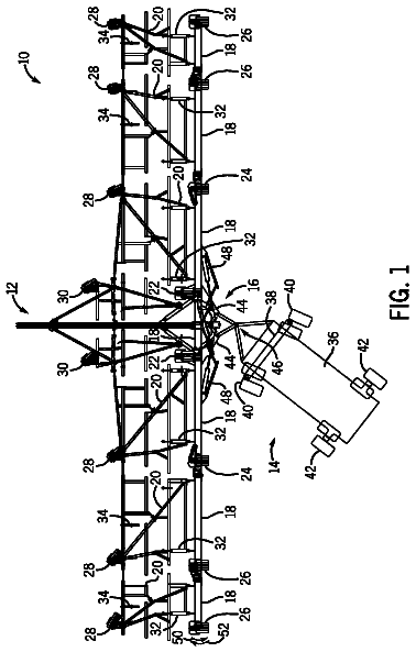
Implement with tool bar behind wing frames

An agricultural implement including a hitch assembly configured to couple to a tow vehicle, a plurality of wing tool bars coupled transversely to the hitch assembly, and a plurality of wing frames pivotally coupled to…

Filed2011
LapsedMay 2026
OwnerCNH Industrial Canada, Ltd.
Drawing from US 8,727,840 B2Lapsed, fee not paid5 drawings
Agriculture & Food Tech · US 8,727,840 B2

Method of cutting a pork loin

A method of cutting a pork loin creating an anterior portion, a center portion, and posterior portion of a pork loin to provide pork products having enhanced value.

Filed2012
LapsedMay 2026
OwnerTyson Foods, Inc.