Cross reference to related applications
This application claims the benefit of U.S. Provisional Patent Application Ser. No. 60/821,523, filed Aug. 4, 2006, titled "KINEMATICS COMPENSATION OBJECT ORIENTED SYSTEM AND METHOD FOR MACHINE TOOL CONTROL", and U.S. Provisional Patent Application Ser. No. 60/821,503, filed Aug. 4, 2006, titled "SYSTEM AND METHOD FOR TOOL CENTER POINT MANAGEMENT", the disclosures of which are expressly incorporated by reference herein including the source code appendix of each.
Further, this application is related to U.S. patent application Ser. No. 11/833,958, filed Aug. 3, 2007, titled "MACHINE TOOL SYSTEM CONTROL", the disclosure of which is expressly incorporated by reference herein.
Background and summary of the invention
The invention relates to machine tool control software. More specifically, the field of the invention is that of machine tool control software for object oriented machine tool control software and the operation of machine tool control software.
An object oriented machine tool control system may provide real-time machine tool software system control that isolates system responsibilities into classes that permit a machine tool manufacturer or system integrator to manage complexity and change. One example of a machine tool control system is disclosed in U.S. Pat. No. 5,453,933, assigned to the assignee of the present invention, the disclosure of which is incorporated by reference herein. The system of the '933 patent allows different systems to be created from a core set of procedures without redesigning or making massive software changes.
Engineers changing a control system of the '933 patent may easily make changes to the system because they do not need to be experts on the entire system to make a modification to a single component in a class. One change does not have a ripple effect of change throughout the system. Portions of the system that are most likely to change such as the user interface and device drivers are separated from the Kernel. These components are more accessible to change through PLC programs, customizations to the Machine class and addition to or modification of operator programs.
In an exemplary embodiment of the present disclosure, a motion control system is provided for a machine tool system. In an example of the present disclosure, the motion control system includes a generalized kinematics library which may model various machine tool systems. In a further example, multiple instances of the generalized kinematics library are generated to provide data for the machine tool system or other machine tool systems.
In a further exemplary embodiment of the present disclosure, a method for controlling the movement of a machine tool system to machine a part is provided. The method comprising the steps of contacting the part with a tool and moving the tool relative to the part from a first position to a second position while the tool remains in contact with the part. The tool interpolating through a machine singularity point of the machine tool system.
In another exemplary embodiment of the present disclosure, a method for determining position information for a plurality of moveable axes of a machine tool system to machine a part is provided. The method comprising the steps of providing a cascading method accepting a plurality of different tool position input types; receiving a first tool position, the first tool position corresponding to one of the plurality of different input types; and determining with the cascading method the positional information based on the received first tool position.
In yet another exemplary embodiment of the present disclosure, a method for controlling the movement of a machine tool system to machine a part, the machine tool system having a plurality of rotatable axes. The method comprising the steps of contacting the part with a tool at a first position; identifying a second position to move the tool; and selecting a shortest angular traverse solution for each of the plurality of rotatable axes from a plurality of possible solutions for each of the plurality of rotatable axes.
In yet a further exemplary embodiment of the present disclosure, a method for controlling the movement of a machine tool system to machine a part, the machine tool system having a plurality of rotatable axes including a tilt axis. The method comprising the steps of contacting the part with a tool at a first position; identifying a second position to move the tool; and selecting a first solution for each the plurality of rotatable axes from a plurality of possible solutions for each of the plurality of rotatable axes based on a specified tilt axis preference. The first solution having a tilt angle for the tilt axis which satisfies the tilt axis preference.
In still another exemplary embodiment of the present disclosure, a method for controlling the movement of a machine tool system to machine a part, the machine tool system having a plurality of moveable axes. The method comprising the steps of contacting the part with a tool at a first position; identifying a second position to move the tool; and determining a plurality of interpolated positions from the first position to the second position with a two stage interpolation method.
In still yet another exemplary embodiment of the present disclosure, an apparatus for machining a part with at least one tool. The apparatus comprising a frame; a moveable support supported by and moveable relative to the frame, the moveable support supporting the part; a machine tool spindle supported by the frame and moveable relative to the part, the machine tool spindle adapted to couple the at least one tool, the moveable support and the machine tool spindle including a plurality of moveable axes; and a motion control system operably coupled to the machine tool spindle and the moveable support. The motion control system executing the machining of the part through the controlled movement of the plurality of moveable axes of the machine tool spindle and the moveable support. The motion control system contacts the part with a first tool at a first position and moves the first tool relative to the part from the first position to a second position while the first tool remains in contact with the part. The first tool interpolating through a machine singularity point of the machine tool system.
In further still another exemplary embodiment of the present disclosure, an apparatus for machining a part with at least one tool. The apparatus comprising a frame; a moveable support supported by and moveable relative to the frame, the moveable support supporting the part; a machine tool spindle supported by the frame and moveable relative to the part, the machine tool spindle adapted to couple the at least one tool, the moveable support and the machine tool spindle including a plurality of moveable axes; and a motion control system operably coupled to the machine tool spindle and the moveable support. The motion control system executing the machining of the part through the controlled movement of the plurality of moveable axes of the machine tool spindle and the moveable support, wherein the motion control system contacts the part with a first tool at a first position and moves the first tool relative to the part from the first position to a second position by selecting a shortest angular traverse solution for each of a plurality of rotatable axes of the plurality of moveable axes from a plurality of possible solutions for each of the plurality of rotatable axes.
In another exemplary embodiment of the present disclosure, an apparatus for machining a part with at least one tool is provided. The apparatus comprising a frame; a moveable support supported by and moveable relative to the frame, the moveable support supporting the part; a machine tool spindle supported by the frame and moveable relative to the part, the machine tool spindle adapted to couple the at least one tool, the moveable support and the machine tool spindle including a plurality of moveable axes; and a motion control system operably coupled to the machine tool spindle and the moveable support. The motion control system executing the machining of the part through the controlled movement of the plurality of moveable axes of the machine tool spindle and the moveable support. The motion control system contacts the part with a first tool at a first position and moves the first tool relative to the part from the first position to a second position by selecting a first solution for each of a plurality of rotatable axes of the plurality of moveable axes from a plurality of possible solutions for each of the plurality of rotatable axes based on a specified tilt axis preference, the first solution having a tilt angle which satisfies the tilt axis preference for a tilt axis of the plurality of the moveable axes.
In still another exemplary embodiment of the present disclosure, an apparatus for machining a part with at least one tool is provided. The apparatus comprising a frame; a moveable support supported by and moveable relative to the frame, the moveable support supporting the part; a machine tool spindle supported by the frame and moveable relative to the part, the machine tool spindle adapted to couple the at least one tool, the moveable support and the machine tool spindle including a plurality of moveable axes; and a motion control system operably coupled to the machine tool spindle and the moveable support. The motion control system executing the machining of the part through the controlled movement of the plurality of moveable axes of the machine tool spindle and the moveable support. The motion control system contacts the part with a first tool at a first position and moves the first tool relative to the part from the first position to a second position by determining a plurality of interpolated positions from the first position to the second position with a two stage interpolation method.
In a further exemplary embodiment of the present disclosure, a method for controlling the movement of a machine tool system to machine a part is provided. The method comprising the steps of receiving a machine configuration corresponding to the machine tool system, the machine configuration identifying a plurality of moveable axes of the machine tool system and a plurality of interdependencies therebetween; generating based on the machine configuration and a generalized kinematics library a virtual kinematics machine; receiving input data corresponding to a shape of the part; and generating positions for the plurality of moveable axes of the machine tool system based on the virtual kinematics machine and the input data.
In another exemplary embodiment of the present disclosure, a method for controlling the movement of a machine tool system having a plurality of moveable axes to machine a part is provided. The method comprising the steps of receiving input data corresponding to a shape of the part; generating a first virtual kinematics machine based on a machine configuration of the machine tool system and a generalized kinematics library, the first virtual kinematics machine generating positions for the plurality of moveable axes of the machine tool system based on the input data; and generating a second virtual kinematics machine based on the machine configuration of the machine tool system and the generalized kinematics library, the second virtual kinematics machine generating position information for a moveable portion of the machine tool system.
In yet still another exemplary embodiment of the present disclosure, a method of programming multiple machine tool systems with a software controller is provided. The method comprising the steps of providing a generalized kinematics library accessible by the software controller; generating a first virtual kinematics machine having a first configuration corresponding to a first machine tool system, the first virtual kinematics machine based on the generalized kinematics library; and generating a second virtual kinematics machine having a second configuration corresponding to a second machine tool system, the second virtual kinematics machine based on the generalized kinematics library.
In another exemplary embodiment of the present disclosure, an apparatus for machining a part with at least one tool is provided. The apparatus comprising a frame; a moveable support supported by and moveable relative to the frame, the moveable support supporting the part; a machine tool spindle supported by the frame and moveable relative to the part, the machine tool spindle adapted to couple the at least one tool, the moveable support and the machine tool spindle including a plurality of moveable axes; and a motion control system operably coupled to the machine tool spindle and the moveable support, the motion control system executing the machining of the part through the controlled movement of the plurality of moveable axes of the machine tool spindle and the moveable support. The controlled movement of the plurality moveable axes is provided by an instance of a generalized kinematics library. The instance including a plurality of virtual axes which correspond to the plurality of moveable axis.
In still a further exemplary embodiment of the present disclosure, a method of configuring a software controller of a machine tool system is provided. The method comprising the steps of providing a generalized kinematics library accessible by the software controller; receiving information regarding a configuration of the machine tool system, the machine tool system having a plurality of orthogonal moveable axes; generating an instance of the generalized kinematics library which corresponds to the machine tool system based on the received information regarding the configuration of the machine tool system; and controlling a movement of the plurality of orthogonal moveable axes through the instance of the generalized kinematics library.
In a further exemplary embodiment of the present disclosure, a computer readable medium having computer-executable instructions for controlling the movement of a plurality of moveable axes of a machine tool system to machine a part is provided. The computer executable instructions comprising a generalized kinematics library; instructions to generate an instance of the generalized kinematics library based on a configuration of the machine tool system; instructions to provide input data to the instance of the generalized kinematics library; and instructions to get output data from the generalized kinematics library, the output data being related to the movement of the plurality of moveable axes.
Brief description of the drawings
The above mentioned and other features and objects of this invention, and the manner of attaining them, will become more apparent and the invention itself will be better understood by reference to the following description of an embodiment of the invention taken in conjunction with the accompanying drawings, wherein:
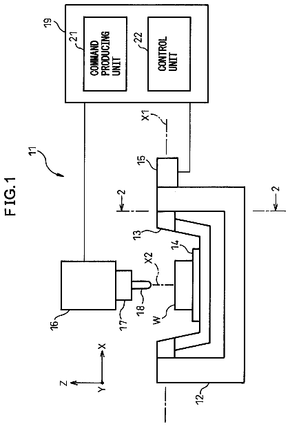
FIG. 1 illustrates an exemplary machine tool system;
FIG. 2 illustrates a representative view of the of a motion control system of the exemplary machine tool system of FIG. 1;
FIG. 3 illustrates a representative view of axis objects;
FIGS. 4A and 4B illustrate exemplary input screens of a user interface for providing characteristics regarding a rotary C-axis;
FIGS. 5A and 5B illustrate exemplary input screens of a user interface for providing characteristics regarding a rotary C-axis;
FIG. 6 illustrates an exemplary input screen for specifying the interdependencies between a plurality of axes of the machine tool system of FIG. 1;
FIGS. 7A and 7B illustrate representative views of the Tool Matrix Stack and the Part Matrix Stack;
FIG. 8 illustrates a representative view of a cascade method of the motion control system of FIG. 2;
FIGS. 9A-9C relate to a method to determine the rotary angle of the tilt axis of the machine tool system of FIG. 1;
FIGS. 10A-C illustrate a machine singularity point for various machine tool systems;
FIG. 11A illustrates a machine singularity point of the machine tool system of FIG. 1;
FIG. 11B illustrates a tilt angle corresponding to a positive tilt axis preference;
FIG. 11C illustrates a tilt angle corresponding to a negative tilt axis preference;
FIGS. 12A-D illustrate that a tool remains in contact with a part during a rotation about the machine singularity point;
FIGS. 13A-C represent a method which interpolates the tool vector from last position at the machine singularity point, rotates about the machine singularity point, and then interpolates the tool vector from the machine singularity point to next tool position;
FIG. 14A illustrates a last tool vector position and a next tool vector position;
FIG. 14B illustrates a plane defined by the tool vector for the last position and the tool vector for the next position about the coordinate system origin and includes a tool vector that coincides with the machine singularity point;
FIG. 14C illustrates a move from the last position to the next position solution #1;
FIGS. 15A-C represent a method which interpolates the tool vector from last position to the machine singularity point, rotates about the machine singularity point, and then interpolates the tool vector from the machine singularity point to next tool position.
FIGS. 16A and 16B illustrate a last position and a first solution of a next position, both the last position and the first solution of next position having a negative tilt angle on the same side of the machine singularity point;
FIGS. 17A-B illustrate a last position and a first solution of a next position having a tilt axis angle on the tilt axis preference side with a 180 degree rotary axis rotation;
FIG. 17C illustrates a second solution of the next position for FIG. 17A which is chosen if the tilt axis angle for the first solution in FIG. 17B is not on the tilt axis preference side with a zero degree rotary axis rotation;
FIGS. 18A-C represents a case where the tool vector should not interpolate through the singularity point and the correct Solution #2 must be selected;
FIG. 19 represents a chord error;
FIG. 20 illustrates a transform plane;
FIG. 21 illustrates an exemplary input screen for specifying a tilt axis preference and various parameters;
FIG. 22 illustrates the relationship between a surface contact point at a surface normal, a tool vector and the and a tool bottom center point;
FIG. 23 illustrates the selection of a tool bottom center point in a case having multiple solutions;
FIG. 24 illustrates a tool vector interpolation from a last position to a next position;
FIG. 25 illustrates interpolated tool vectors; and
FIG. 26 illustrates a correspondence between the Boolean Decision Matrix and the Transformation Matrix.
Corresponding reference characters indicate corresponding parts throughout the several views.
Detailed description of the drawings
The embodiments disclosed herein are not intended to be exhaustive or limit the invention to the precise form disclosed in the following detailed description. Rather, the embodiment is chosen and described so that others skilled in the art may utilize its teachings.
Referring to FIG. 1, a machine tool system 100 is shown having a motion control system 200. Machine tool system 100 includes a frame 102 having a first saddle 104 coupled thereto. Saddle 104 is translatable in directions 106 and 108. A second saddle 110 is supported by first saddle 104. Saddle 110 is translatable in directions 112 and 114 relative to saddle 104. A platform 120 is supported by saddle 110 and is rotatable relative to saddle 110 in directions 122 and 124. In one embodiment, each of saddle 104, saddle 110, and platform 120 are moveable through motors which are controlled by motion control system 200.
Further, a third saddle 126 is supported by frame 102. Saddle 126 is translatable in directions 128 and 130. Saddle 126 supports a rotatable member 132. Rotatable member 132 is rotatable in directions 134 and 136 relative to saddle 126. In one embodiment, each of saddle 126 and rotatable member 132 are moveable through motors which are controlled by motion control system 200.
A tool spindle 138 is supported by platform 132. Various tools 141 may be coupled to tool spindle 138 to perform various operations with machine tool system 100. Exemplary tools include and an end mill, a drill, a tap, a reamer, and other suitable tools. Tool spindle 138 is rotatable about a tool spindle axis 139 to input a rotation to the tool 141. In one embodiment, a plurality of tools 141 are stored in a tool carousal 144. Additional details about tool carousal 144 are provided in U.S. Provisional Application Ser. No. 60/821,481, the disclosure of which is expressly incorporated by reference herein.
The movement of saddle 104 in direction 106 or direction 108 is illustrated as a movement in an y-axis 150. The movement of saddle 110 in direction 112 or direction 114 is illustrated as a movement in an x-axis 152. The movement of saddle 126 in direction 128 and direction 130 is illustrated as a movement in an z-axis 154. The rotation of rotatable member 132 in direction 134 or direction 136 is illustrated as a movement in an B-axis 156. The rotation of platform 120 in direction 122 or direction 124 is illustrated as a movement in an C-axis 158. Machine tool system 100 is an exemplary 5-axis machine. In one embodiment, one of B-axis 156 and C-axis 158 is replaced with an A-axis wherein platform 120 is tiltable about one of x-axis 152 and y-axis 150.
Through the movement of one or more of the 5-axes of machine tool system 100 a tool 141 may be positioned relative to a part 160 (see FIG. 9A) supported by platform 120 to be machined. Part 160 may be secured to platform 120 to maintain the position of part 160 to platform 120.
The movement of one or more of the 5-axes of machine tool system 100 is controlled through motion control system 200. Referring to FIG. 2, motion control system 200 includes a software controller 202 and one or more I/O modules 206. It should be understood that the methods disclosed herein may be executed by software controller 202 and be stored in a manner associated with software controller 202.
Software controller 202 receives a machine configuration 208 and input data, such as a part program 204, and then provides output data, such as position data for the various axes 150, 152, 154, 156, and 158 of machine tool system 100. In the illustrated example in FIG. 2, software controller 202 receives part program 204 and machine configuration 208 from one or more I/O modules 206. Machine configuration 208 provides the dependencies between the various axes 150, 152, 154, 156, and 158 of machine tool system 100 as well as the attributes of each axis. For instance, as saddle 104 moves in direction 106 the location of C-axis 158 is changed. Therefore, the location of C-axis 158 depends on the location of saddle 104.
Exemplary I/O modules 206 includes input members, such as a user interface, a touch display, a keyboard, a mouse, one or more buttons or switches, a CD drive, a floppy drive, an interface to a determiner network (wireless or wired), and other suitable devices for providing information to software controller 202 and output members, such as a display (such as a touch screen), lights, printer, and other suitable devices for presenting information.
In one embodiment, part program 204 is entered through a conversational mode of operation whereby a user during a programming session is presented with one or more screens through a user interface (such as a touch screen and keyboard). An exemplary method of conversational programming is disclosed in U.S. Pat. No. 5,453,933, assigned to the assignee of the current application, the disclosure of which is expressly incorporated by reference herein. During the programming session, the user may program the desired geometry for the machined part and specify one or more attributes. In one example, the user specifies the desired geometry for the machined part by creating blocks of code each of which specifies a tool and a trajectory of the tool. As such, the geometry of the machined part is defined based on the operations used to create the machined part.
In one embodiment, part program 204 is provided through a NC mode of operation whereby an NC program is loaded into software controller 202. Part programs are frequently expressed in a standard G&M code language, or a close derivative of this language based on either the International Standards Organization (ISO) or the Electronics Industries Association (EIA) RS-274-D, using codes identified by letters such as G, M, F. The codes define a sequence of machining operations to control motion in the manufacture of a part. Software controller 202 converts the codes to provide location positions for the various axes 150, 152, 154, 156, and 158 of machine tool system 100. In one embodiment, part program 204 is parsed by a parser 220 of software controller 202. Parser 220 reviews part program 204 and identifies various geometry segments. Exemplary geometry segments include lines and arcs.
Regardless of the origin of part program 204, part program 204 defines the desired geometry for the machined part either directly or based on the operations used to create the part. However, part program 204 may not specify the positions of saddles 104, 110, and 126 nor the rotations of platform 120 and rotatable member 132. These positions are determined by software controller 202.
In one embodiment, software controller 202 is an object-oriented software component. In one embodiment, software controller 202 is based on the software described in U.S. Pat. No. 5,453,933 issued on Sep. 26, 1995 and titled CNC CONTROL SYSTEM, the disclosure of which is expressly incorporated by reference herein.
In one embodiment, software controller 202 includes an object oriented generalized kinematics library 210 and one or more host software applications 215. The host software application 215 interfaces with instances (identified herein as virtual kinematics machines 214, 234, and 236) of the generalized kinematics library 210 through an interface, such as an API interface 217. Host software application 215 also interfaces with other components of software controller 202, such as the real time application for the real time mill and the graphics application.
Generalized kinematics library 210 includes a collection of objects or classes from which objects may be derived that are used to develop virtual kinematics machine 214 from an instance of the library 210. In one embodiment, the machine configuration 208 is provided to software controller 202. Based on machine configuration 208 software controller 202 creates the virtual kinematics machine 214 from the kinematics library 210. Virtual kinematics machine 214 is stored in memory. Virtual kinematics machine 214 has the same configuration as the actual machine described in the machine configuration 208.
Design Overview of Generalized Kinematics Library
The Generalized Kinematics Library contains an application programming interface (API) 217 that a host software application 215 uses to communicate data via Set data functions and receive data via Get data functions. Thus, as per the object oriented design paradigm, the host software application 215 cannot directly access private member data in the generalized kinematics library 210 or instances thereof.
Interfacing to the Generalized Kinematics Library
The host software application 215 interfaces to the generalized kinematics library 210 through an API 217 designed using the object-oriented paradigm by communicating data via Set data functions and receiving data via Get data functions.
Generalized Kinematics Library Initialization
In accordance with object oriented paradigm, the host software application 215 initializes the virtual kinematics machines with the data required for the generalized kinematics library 214 to assemble the virtual kinematics machine 214. The host software application 215 begins by creating an instance of the general kinematics library 210. The initialization procedure follows using configuration data 208 about the machine axes that may originate from numerous sources including configuration files, user-input, and or automatic drive recognition by the real-time components of the machine tool system 100.
The host software application 215 cycles through each axis that is present in the system and calls the function AddAxis(ID, Connection). The Axis ID is a number that uniquely identifies the axis. Exemplary axis ids include the set {0,1,2,3,4,5} which corresponds to linear and rotational axes {x,y,z,a,b,c}. With the call of this function, the generalized kinematics library 210 creates an axis object in memory, which can then initialized with any or all of the following data as required for the axis type by the host software application 215.
Each axis may include some or all of the following attributes 303: ID Type (linear/rotary/tilt/spindle) Direction Coordinate location (centerline if rotational axis) Limits Maximum velocities Connection (whether the axis is connected to the tool or to the part)
After all the axes have been created and initialized with the appropriate data, the generalized kinematics library EndSetup( ) function is called by the host software application 215, which validates the machine kinematics, assembles the Tool and Part Matrix Stacks 270 and 280 (see FIGS. 7A and 7B), and determines the tilt axis angle for the machine singularity point if it is a 5-axis machine. The singularity point tilt angle of the tilt axis (B-axis 158) is determined by locating the tilt angle where the spindle axis aligns with the rotary axis, (C-axis 156).
At this point the generalized kinematics library 210 is ready to be used by the host software application 215. Normally the generalized kinematics library 210 is initialized with a starting position, and other initial modes, each of which are explained in more detail herein, are set either on or off including: Shortest angular traverse, Interpolation on/off Interpolation type if on Tilt axis preference direction or off or force use of preference direction Multiple Instances of the Generalized Kinematics Library
The design of the generalized kinematics library 210 allows the host software application 215 to create multiple instances of the generalized kinematics library 210 for different processes (different host software applications within the machine tool control software 200). For example, one instance is used to interpret programs for the real-time running of the actual machine tool system 100. Another instance is used to display the real-time graphics and position data during program runtime on the machine tool system 100. A third instance may be used to interpret programs for different machines to display in graphics. This third instance allows the user to program parts 160 for different machines than that which the software controller 202 is connected to and to check these programs using graphical verification. Each instance of the general kinematics library 210 is independent and may be used simultaneously.
The software controller 202 contains an initialization class that acts as an API layer between the generalized kinematics library 210 and the host application software 215. This configuration permits different components (i.e. different host software applications) within software controller 202 to initialize their instances of the general kinematics library 210 through a common, universally accessible singleton class. The host software applications 215 may also modify the kinematics models for different machines when necessary. An example would be the concurrent programming graphics instance of the generalized kinematics library 210 that may be modified to model machines other than the one the CNC controller 200 is connected to. Also, in one embodiment the general kinematics library 210 permits the simultaneous control of multiple machine tool systems with a single controller.
Using Generalized Kinematics Library in Tool Position Computation Mode for Motion Control
The API to determine machine joint positions for any of the given input types 1 through 4 (see FIG. 8) is a simple overloaded SetPosition(Input Data) function, where Input Data is the requisite data corresponding to Type 4 through Type 1. Interpolation modes, feedrates or time steps, tool information, and part setup are set prior to calling the SetPosition(Input Data) function. The generalized kinematics library 210 updates its internal NextPosition data object with the input data and uses this object to determine the next tool position. When using the generalized kinematics library 210 to determine tool positions, the joint positions and time step for the input move are determined and stored in memory. The generalized kinematics library 210 then updates its internal LastPosition data object with the input and determined data, which will be used to make decisions to determine the next input tool position. The host software application 215 will then pick up the determined information using a GetPositionData( ) function, which returns a reference to a class in the generalized kinematics library 210 that contains the determined data.
The host software application 215 can configure the generalized kinematics library 210 to store additional information other than the machine joint positions and time step for each move. For example, tool tip location with respect to the workpiece, tool vector direction with respect to the machine reference coordinate system 284 (See FIG. 7A).
Using Generalized Kinematics Library in Computation Mode
The generalized kinematics library 210 may be used in a pure computation mode where the LastPosition internal data object does not get updated with the determined tool position. This can be useful when making logical decisions about the tool path in the host software application such as computing the clipping point of an oriented retract plane to the machine limits. The API is a simple overloaded DeterminePosition(Input Data) function, where Input Data is the requisite data corresponding to Type 4 through Type 1. The requisite machine states must be set prior to calling DeterminePosition, which is identical to using SetPosition described in the previous section.
In addition to computing machine joint angles for input tool positions, the generalized kinematics library 210 may also determine tool tip and tool vector data with respect to any of the coordinate systems in the kinematics linkages of the modeled machine. An example would be the computation of the tool vector in the machine reference coordinate given the machine joint positions and angles: GetToolVectorWrtMachine(Machine Joint Positions), where Machine Joint Positions is a vector containing all the relevant axes positions. This function call would not update the generalized kinematics library 210 internal LastPosition data object.
The Virtual Kinematics Machines
Generalized kinematics library 210 consolidates the kinematics calculations in a single library source that can be shared throughout the code. The generalization of the library provides a means for the library to create a virtual kinematics machine of any orthogonal machine tool system of up to 5 axes. In one embodiment, this is achieved with an object-oriented design in which a virtual mathematical model of the machine tool system 100 is created in the library. Although the generalized kinematics library 210 is described herein for use with machine tool systems of up to 5 orthogonal axes, due to the object-oriented design of the generalized kinematics library 210, it can be specialized for non-orthogonal systems and for systems with more than 5 axes. The object-oriented design provides the flexibility to generate a plug-and-play library that may connect and configure itself to model any orthogonal machine tool system from 1 to 5 axes. Further, although described herein for use with a machine tool system 100, the motion control system 200 may be used with any type of motion system including robotics.
Virtual kinematics machine 214 is based on one or more matrix stacks discussed herein. These matrix stacks, such as 270 and 280 in FIGS. 7A and 7B, include matrices that describe the characteristics of one or more of the various axes 150, 152, 154, 156, and 158 of machine tool system 100. Additional characteristics of machine tool system 100 may also be accounted for in the matrix stacks 216. For instance, part 160 is coupled to platform 120.
Axis Objects
Referring to FIG. 3, each axis of the various axes 150, 152, 154, 156, and 158 of machine tool system 100 is described as an object. The axis objects are derived from a generic axis class 302 represented in FIG. 3. Axis class 302 is the base class for all axis objects and defines properties and methods for axis objects. Axis class 302 includes various axis attributes 303 and transformation matrices 305. The Axis base class 302 contains common data and methods that all derived axes objects own.
The following is a list of data included in the Axis base class 302:
Data:
Axis ID=integer {0,1,2,3,4,5,6,7} corresponding to {X,Y,Z,A,B,C,S} Name=string {"X","Y","Z","A","B","C","S") Type=enumeration {Linear, Rotary, Tilt, Spindle} Position=axis position Matrix=axis transformation matrix Connection=enumeration {Tool, Part} MinPosition=lower bound of motion MaxPosition=upper bound of motion AxisLimitsExists=Boolean {True, False} InitialMachineDirection Vector=Vector in Machine reference frame representing positive axis movement direction. For rotation axes, vector direction of axis centerline for Right-hand positive rotation. MaxContourSpeed=interpolation speed MaxRapidSpeed=rapid move speed Methods: Several methods are included in the Axis base class including Set( ) and Get( ) functions for each of the above data.
Derived from axis class 302 are three derived-classes, linear axis 320, spindle axis 321, and rotary axis 322. The SpindleAxis Class 321 is derived from the Axis base class. In addition to the Axis base class 202 data and methods, the SpindleAxis Class 321 includes:
Data:
Location=spindle coordinate system origin with respect to axis it is connected to Methods: SetAxisS( )=initialization function SetInitSpindleAxisDirectionWrtMachine(DirectionVector)=function to set InitialMachineDirection Vector from base Axis class SetLocationWrtLastAxis( )=function to set the location of the spindle coordinate system with respect to the last axis it is connected to
The Linear Axis class 320 is derived from the Axis base class 302. In addition to the axis base class data 302 and methods, the LinearAxis Class 320 includes:
Methods:
Translate( )=functions to translate a vector or multiply a matrix by the linear axis translation matrix SetAxis(x,y,z)=initialization functions
The RotationAxis class 322 is derived from the Axis base class 302. In addition to the Axis base class 302 data and methods, the RotationAxis Class 322 includes:
Data:
Centerline=Location of axis of rotation Methods: SetAxis(a,b,c)=Initialization functions Rotate( )=functions to rotate a vector or multiply a matrix by the rotation GetPerpendicularDistanceToAxis(Point)=function returns perpendicular radial distance to axis of rotation
Based on machine configuration 208, virtual kinematics machine 214 includes five machine specific axis objects 250, 252, 254, 256, and 258 which correspond to axes 150, 152, 154, 156, and 158 of FIG. 1. Exemplary input screens of a user interface of I/O modules 206 are provided for specifying some exemplary attribute information for C-axis 258 (FIGS. 4A and 4B) and for B-axis 256 (FIGS. 5A and 5B).
The description continues in the full USPTO document.
 Lapsed, fee not paid9 drawings