Technical field
This document relates generally to cardiac rhythm management (CRM) systems and particularly to an anti-tachyarrhythmia system that automatically adjusts one or more arrhythmia detection durations using patent-specific and/or tachyarrhythmia event-specific information.
Background
Tachyarrhythmias are abnormal heart rhythms characterized by a rapid heart rate. Tachyarrhythmias generally include supraventricular tachyarrhythmia (SVT, including atrial tachyarrhythmia, AT) and ventricular tachyarrhythmia (VT). Fibrillation is a form of tachyarrhythmia further characterized by an irregular heart rhythm. In a normal heart, the sinoatrial node, the heart's predominant natural pacemaker, generates electrical impulses, called action potentials, that propagate through an electrical conduction system to the atria and then to the ventricles of the heart to excite the myocardial tissues. The atria and ventricles contract in the normal atrio-ventricular sequence and synchrony to result in efficient blood-pumping functions indicated by a normal hemodynamic performance. VT occurs when the electrical impulses propagate along a pathologically formed self-sustaining conductive loop within the ventricles or when a natural pacemaker in a ventricle usurps control of the heart rate from the sinoatrial node. When the atria and the ventricles become dissociated during VT, the ventricles may contract before they are properly filled with blood, resulting in diminished blood flow throughout the body. This condition becomes life-threatening when the brain is deprived of sufficient oxygen supply. Ventricular fibrillation (VF), in particular, stops blood flow within seconds and, if not timely and effectively treated, causes immediate death. In very few instances a heart recovers from VF without treatment.
Cardioversion and defibrillation are used to terminate most tachyarrhythmias, including AT, VT, and VF. An implantable cardioverter/defibrillator (ICD) is a cardiac rhythm management (CRM) device that delivers an electric shock to terminate a detected tachyarrhythmia episode by depolarizing the entire myocardium simultaneously and rendering it refractory. Another type of electrical therapy for tachyarrhythtnia is anti-tachyarrhythmia pacing (ATP). In ATP, the heart is competitively paced in an effort to interrupt the reentrant loop causing the tachyarrhythmia. An exemplary ICD includes ATP and defibrillation capabilities so that ATP is delivered to the heart when a non-fibrillation VT is detected, while a defibrillation shock is delivered when VF occurs.
The efficacy of cardioversion, defibrillation, and ATP in terminating tachyarrhythmia depends on the type and origin of the tachyarrhythmia. An unnecessary therapy delivered during a non-life-threatening tachyarrhythmia episode may cause substantial pain in the patient and reduces the longevity of the ICD while providing the patient with little or no benefit. On the other hand, a necessary therapy withheld during a life-threatening tachyarrhythmia episode may result in irreversible harm, including death. For these and other reasons, there is a need for detecting tachyarrhythmia in a way that ensures patient safety while reducing unnecessary delivery of therapy.
Summary
A CRM system delivers anti-tachyarrhythmia therapies and uses patient-specific and/or tachyarrhythmia event-specific information to automatically set and adjust one or more arrhythmia detection durations. In one embodiment, the CRM system initializes and updates the one or more arrhythmia detection durations using patient-specific information such as medical history and recent medical trends. In another embodiment, the CRM dynamically adjusts the one or more arrhythmia detection durations using the patient's hemodynamic performance. One example of such an arrhythmia detection duration is a sustained rate duration (SRD) that starts when a tachyarrhythmia such as an SVT is detected. An anti-tachyarrhythmia therapy is delivered only if the detected SVT sustains throughout the SRD.
In one embodiment, a CRM system includes a tachyarrhythmia detector and a duration controller. The tachyarrhythmia detector detects a tachyarrhythmia during an arrhythmia detection duration. The duration controller includes a duration timer and a duration adjuster. The duration timer times the arrhythmia detection duration. The duration adjuster includes one or more of a duration initialization module and a dynamic duration adjustment module. The duration initialization module automatically determines an initial value using one or more indication parameters related to an indication for an anti-tachyarrhythmia therapy and sets a base value of the arrhythmia detection duration to the initial value. The dynamic duration adjustment module dynamically adjusts the arrhythmia detection duration using a signal indicative of hemodynamic performance.
In one embodiment, a method for operating a CRM system is provided. An arrhythmia detection duration is timed. A tachyarrhythmia is detected during the arrhythmia detection duration. The arrhythmia detection duration is adjusted automatically using one or more indication parameters related to an indication for an anti-tachyarrhythmia therapy and/or adjusted dynamically using a signal indicative of hemodynamic performance.
In one embodiment, a CRM system includes a tachyarrhythmia detector, a therapy output circuit, a therapy controller, and a duration controller. The tachyarrhythmia detector determines whether a tachyarrhythmia sustains during a sustained rate duration (SRD). The therapy output circuit delivers an anti-tachyarrhythmia therapy. The therapy controller initiates a delivery of the anti-tachyarrhythmia therapy in response to an expiration of the SRD and withholds the delivery of the anti-tachyarrhythmia therapy if the SRD is terminated before the expiration. The duration controller includes a duration timer and a duration adjuster. The duration timer times the SRD. The duration adjuster receives a sensed physiologic signal and/or stored patient-specific information, and automatically adjusts the SRD using the sensed physiologic signal and/or the stored patient-specific information.
In one embodiment, a method for operating a CRM system is provided. A sensed physiologic signal and/or stored patient-specific information are received. An SRD is automatically adjusted using the sensed physiologic signal and/or the stored patient-specific information. Whether a tachyarrhythmia sustains is determined during the SRD. A delivery of an anti-tachyarrhythmia therapy is initiated in response to an expiration of the SRD. The delivery of the anti-tachyarrhythmia therapy is withheld if the SRD is terminated before expiring.
This Summary is an overview of some of the teachings of the present application and not intended to be an exclusive or exhaustive treatment of the present subject matter. Further details about the present subject matter are found in the detailed description and appended claims. Other aspects of the invention will be apparent to persons skilled in the art upon reading and understanding the following detailed description and viewing the drawings that form a part thereof, each of which are not to be taken in a limiting sense. The scope of the present invention is defined by the appended claims and their legal equivalents.
Brief description of the drawings
The drawings, which are not necessarily drawn to scale, illustrate generally, by way of example, but not by way of limitation, various embodiments discussed in the present document.
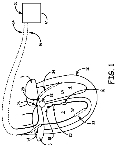
FIG. 1 is an illustration of an embodiment of a CRM system including an anti-tachyarrhythmia system with adjustable arrhythmia detection duration and portions of the environment in which the CRM system operates.
FIG. 2 is a block diagram illustrating an embodiment of an tachyarrhythmia detection system of the anti-tachyarrhythmia system.
FIG. 3 is a block diagram illustrating an embodiment of the anti-tachyarrhythimia system.
FIG. 4 is a flow chart illustrating an embodiment of a method for controlling an anti-tachyarrhythmia therapy using a sustained rate duration (SRD).
FIG. 5 is a flow chart illustrating an embodiment of a method for initializing the SRD.
FIG. 6 is a flow chart illustrating an embodiment of a method for updating the SRD.
FIG. 7 is a flow chart illustrating an embodiment of a method for dynamically adjusting the SRD using a hemodynamic signal.
FIG. 8 is a flow chart illustrating an embodiment of a method for controlling two anti-tachyarrhythmia therapies using two adjustable SRDs.
Detailed description
In the following detailed description, reference is made to the accompanying drawings which form a part hereof, and in which is shown by way of illustration specific embodiments in which the invention may be practiced. These embodiments are described in sufficient detail to enable those skilled in the art to practice the invention, and it is to be understood that the embodiments may be combined, or that other embodiments may be utilized and that structural, logical and electrical changes may be made without departing from the scope of the present invention. The following detailed description provides examples, and the scope of the present invention is defined by the appended claims and their legal equivalents.
In this document, the terms "a" or "an" are used, as is common in patent documents, to include one or more than one. In this document, the term "or" is used to refer to a nonexclusive or, unless otherwise indicated. Furthermore, all publications, patents, and patent documents referred to in this document are incorporated by reference herein in their entirety, as though individually incorporated by reference. In the event of inconsistent usages between this documents and those documents so incorporated by reference, the usage in the incorporated reference(s) should be considered supplementary to that of this document; for irreconcilable inconsistencies, the usage in this document controls.
It should be noted that references to "an", "one", or "various" embodiments in this document are not necessarily to the same embodiment, and such references contemplate more than one embodiment.
The relationship between a heart rate and a cardiac cycle length (also known as cardiac interval), as used in this document, is the relationship between a frequency and its corresponding period. If a heart rate is given in beats per minute (bpm), its corresponding cardiac cycle length in milliseconds is calculated by dividing 60,000 by the heart rate (where 60,000 is the number of milliseconds in a minute). Any process, such as a comparison, using a heart rate is to be modified accordingly when a cardiac cycle length is used instead. For example, if a tachyarrhythmia is detected when the ventricular rate exceeds a tachyarrhythmia threshold rate, an equivalent process is to detect the tachyarrhythmia when the ventricular cycle length (also known as ventricular interval) falls below a tachyarrhythmia threshold interval. The appended claims should be construed to cover such variations.
In this document, a "fast beat" refers to a heart beat having a heart rate that falls into a tachyarrhythmia detection zone, which is typically defined by at least one tachyarrhythmia detection threshold, and a "slow beat" refers to a heart beat having a heart rate that is below the tachyarrhythmia detection zone. In other words, a "fast beat" is a heart beat having a tachyarrhythmic heart rate, and a "slow beat" is a heart beat having a heart rate that is not tachyarrhythmic. A paced heart beat is typically considered as a slow beat.
This document discusses a CRM system that delivers anti-tachyarrhythmia therapies and uses patient-specific and/or tachyarrhythmia event-specific information to automatically set and adjust one or more arrhythmia detection durations. In one embodiment, the system initializes and updates the one or more arrhythmia detection durations for a patient using the patient's medical record including information such as medical history and recent medical trends. In another embodiment, the system dynamically adjusts the one or more arrhythmia detection durations using the patient's hemodynamic performance sensed during a tachyarrhythmia episode. The one or more arrhythmia detection durations include one or more durations within which an arrhythmia is detected, verified, classified, or otherwise analyzed, as illustrated by the following example.
In one example of an ICD that delivers ventricular cardioversion/defibrillation pulses, a detection of three consecutive fast beats from a ventricular electrogram starts a tachyarrhythmia detection and classification process. In response to the detection of three consecutive fast beats, a tachyarrhythmia detection window is started. The tachyarrhythmia detection window includes ten consecutively detected heart beats starting with and including the three consecutive fast beats. If at least eight out of the ten heart beats in the tachyarrhythmia detection window are fast beats (i.e., the tachyarrhythmia detection window is satisfied), a tachyarrhythmia verification duration is started. Otherwise, the tachyarrhythmia detection and classification process is terminated without delivering a ventricular anti-tachyarrhythmia therapy.
During the tachyarrhythmia verification duration, a moving verification window of ten consecutively detected heart beats is used to determine whether the detected tachyarrhythmia sustains. If at least six out of the ten heart beats in the verification window are fast beats (i.e., the verification window is satisfied), the detected tachyarrhythmia is considered to be sustaining. If this verification window fails to be satisfied at any time during the tachyarrhythmia verification duration, the tachyarrhythmia detection and classification process is terminated without delivering a ventricular anti-tachyarrhythmia therapy. If the detected tachyarrhythmia episode is determined to be sustaining throughout the tachyarrhythmia verification duration, it is classified by its origin and/or type to determine whether a ventricular anti-tachyarrhythmia therapy will be necessary.
If the detected tachyarrhythmia episode is classified as a type of tachyarrhythmia for which a ventricular cardioversion/defibrillation therapy is to be delivered, such as a VT episode, the preparation for the ventricular cardioversion/defibrillation therapy is started. After the preparation is completed, a tachyarrhythmia reconfirmation window of three consecutive heart beats is started, immediately before a scheduled ventricular cardioversion/defibrillation pulse delivery. If at least two out of the three heart beats in the tachyarrhythmia reconfirmation window are fast beats (i.e., the tachyarrhythmia reconfirmation window is satisfied), the detected tachyarrhythmia is considered to be still sustaining, and the ventricular cardioversion/defibrillation pulse is delivered.
If the detected tachyarrhythmia episode is classified as a type of tachyarrhythmia for which no ventricular anti-tachyarrhythmia therapy is needed, such as an SVT episode, a sustained rate duration (SRD), also similarly referred to in the art as High Rate Timeout.TM. (Medtronic, Inc.) and Maximum Time to Diagnosis.TM. (St. Jude Medical, Inc.), is started. During the SRD, the heart rate is monitored to determine whether the tachyarrhythmia episode sustains. If the tachyarrhythmia episode sustains throughout the SRD, the ventricular anti-tachyarrhythmia therapy is delivered when the SRD expires even though the detected tachyarrhythmia episode is classified as an SVT episode. The tachyarrhythmia episode sustains if the heart rate remains within a predetermined tachyarrhythmia rate detection zone (such as a VT rate detection zone). In one embodiment, the tachyarrhythmia episode is considered sustaining when an average heart rate (such as an average of heart rates detected within a moving window) falls within the predetermined tachyarrhythmia rate detection zone. In another embodiment, the tachyarrhythmia episode is considered sustaining when a predetermined majority of heart beats within a moving detection window are fast beats, such as when at least six out of ten heart beats are fast beats. In one embodiment, the SRD is programmable between 10 seconds and 60 minutes, with approximately three minutes as a specific example. The SRD is applied to determine whether a detected tachyarrhythmia needs to be treated because of a sustaining high heart rate, after the tachyarrhythmia is classified to be a type that is not to be treated. Thus, the SRD functions as a "safety net" capable of overriding a tachyarrhythmia classification to deliver a therapy. The length of the SRD should reflect a balanced consideration between prompt treatment for a potentially life-threatening tachyarrhythmia and avoidance of an unnecessary yet painful treatment. While the SRD may be programmable by a user such as a physician or other caregiver, the optimization of its value is typically difficult to perform manually before programming the ICD for each individual patient.
As illustrated in the example above, an "arrhythmia detection duration" as used in this document includes any duration within which an arrhythmia is detected, verified, classified, or otherwise analyzed. In various embodiments, such arrhythmia detection durations are specified by a time interval or by number of heart beats. Examples of such an arrhythmia detection duration include the tachyarrhythmia detection window, the tachyarrhythmia verification duration, the verification window, the tachyarrhythmia reconfirmation window, and the SRD. The SRD is specifically discussed below as an example of the arrhythmia detection duration in the present system. Generally, the SRD is substantially longer than many other arrhythmia detection durations, and therefore the automatic adjustment of its length has more significant impact in the overall performance of the ICD.
FIG. 1 is an illustration of one embodiment of a CRM system 100 and portions of the environent in which CRM system 100 operates. CRM system 100 includes an implantable medical device 101 that is electrically coupled to a heart 199 through leads 105 and 110. An external system 102 communicates with implantable medical device 101 via a telemetry link 103.
Implantable medical device 101 delivers anti-tachyarrhythmia therapies such as ATP and cardioversion/defibrillation therapies. In one embodiment, implantable medical device 101 is an implantable cardioverter/defibrillator (ICD) with cardiac pacing capabilities. In another embodiment, in addition to a pacemaker and a cardioverter/defibrillator, implantable medical device 101 further includes one or more of other monitoring and/or therapeutic devices such as a neural stimulator, a drug delivery device, and a biological therapy device. Implantable medical device 101 includes a hermetically sealed can housing an electronic circuit that senses physiological signals and delivers therapeutic electrical pulses. The hermetically sealed can also functions as an electrode for sensing and/or pulse delivery purposes. In one embodiment, as illustrated in FIG. 1, the electronic circuit senses at least an atrial electrogram and a ventricular electrogram from heart 199 and delivers pacing and cardioversion/defibrillation pulses to heart 199. Lead 105 is a pacing lead that includes a proximal end 106 connected to implantable medical device 101 and a distal end 107 placed in the right atrium (RA) of heart 199. A pacing-sensing electrode 108 is located at distal end 107. Another pacing-sensing electrode 109 is located near distal end 107. Electrodes 108 and 109 are electronically connected to implantable medical device 101 via separate conductors in lead 105 to allow sensing of the atrial electrogram and/or delivery of atrial pacing pulses. Lead 110 is a defibrillation lead that includes a proximal end 111 connected to implantable medical device 101 and a distal end 112 placed in the right ventricle (RV) of heart 199. A pacing-sensing electrode 113 is located at distal end 112. A defibrillation electrode 114 is located near distal end 112 but electrically separated from pacing-sensing electrode 113. Another defibrillation electrode 115 is located at a distance from distal end 112 for supraventricular placement. Electrodes 113, 114, and 115 are electrically connected to implantable medical device 101 via separate conductors in lead 110. Electrode 113 allows sensing of the ventricular electrogram and/or delivery of ventricular pacing pulses. Electrodes 114 and 115 allow delivery of ventricular cardioversion/defibrillation pulses.
CRM system 100 includes an anti-tachyarrthythmia system 120 that uses at least one adjustable arrhythmia detection duration such as the SRD. The adjustable arrhythmia detection duration has a base value that is initialized to a value determined based on a patient's medical history including one or more indication parameters related to an indication for the anti-tachyarrhythmia therapy. Such indication parameters include patient demographics that indicate the likeliness that a cardiac condition detected from the patient is related to a tachyarrhythmia episode that requires the anti-tachyarrhythmia therapy. The base value is updated based on one or more trend parameters related to a recent trend of one of the patient's medical conditions. When being timed for tachyarrhythmia detection, the arrhythmia detection duration is dynamically adjusted using a sensed signal indicative of the patient's hemodynamic performance. In one embodiment, as illustrated in FIG. 1, anti-tachyarrhythmia system 120 is within implantable medical device 101. In another embodiment, anti-tachyarrhythmia system 120 is distributed in both implantable medical device 101 and external system 102. For example, the value of the arrhythmia detection duration may be initialized in external system 102, but updated and dynamically adjusted by implantable medical device 101. In another example, the base value of the arrhythmia detection duration is initialized and updated in external system 102 and programmed into implantable medical device 101. When being timed for tachyarrhythmia detection, the arrhythmia detection duration is dynamically adjusted in implantable medical device 101.
External system 102 allows for programming of implantable medical device 101 and receives signals acquired by implantable medical device 101. In one embodiment, external system 102 includes a programmer. In another embodiment, external system 102 is a patient management system including an external device in proximity of implantable medical device 101, a remote device in a relatively distant location, and a telecommunication network linking the external device and the remote device. The patient management system allows access to implantable medical device 101 from a remote location, such as for monitoring patient status, adjusting therapies, and obtaining patient's medical records stored in a remote location. Telemetry link 103 is a wireless communication link providing for bidirectional data transmission between implantable medical device 101 and external system 102. In one embodiment, telemetry link 103 is an inductive telemetry link. In an alternative embodiment, telemetry link 103 is a far-field radio-frequency telemetry link. Telemetry link 103 provides for data transmission from implantable medical device 101 to external system 102. This may include, for example, transmitting real-time physiological data acquired by implantable medical device 101, extracting physiological data acquired by and stored in implantable medical device 101, extracting therapy history data stored in implantable medical device 101, and extracting data indicating an operational status of implantable medical device 101 (e.g., battery status and lead impedance). Telemetry link 103 also provides for data transmission from external system 102 to implantable medical device 101. This may include, for example, programming implantable medical device 101 to acquire physiological data, programming implantable medical device 101 to perform at least one self-diagnostic test (such as for a device operational status), programming implantable medical device 101 to enable an available monitoring or therapeutic function, and programming implantable medical device 101 to adjust therapeutic parameters such as pacing and/or cardioversion/defibrillation parameters.
Anti-tachyarrhythmia system 120 may be implemented using a combination of hardware and software. In various embodiments, each element of anti-tachyarrhythmia system 120, including its specific embodiments, may be implemented using an application-specific circuit constructed to perform one or more particular functions or a general-purpose circuit programmed to perform such function(s). Such a general-purpose circuit includes, but is not limited to, a microprocessor or portions thereof, a microcontroller or portions thereof, and a programmable logic circuit or portions thereof For example, a "timer" includes, among other things, an electronic circuit timer constructed to perform the only function of timing a specified duration or a portion of a general-purpose circuit driven by a code instructing that portion of the general-purpose circuit to perform the timing of the specified duration.
FIG. 2 is a block diagram illustrating an embodiment of a tachyarrhythmia detection system 230, which is part of anti-tachyarrhythmia system 120. Tachyarrhythmia detection system 230 includes a tachyarrhythmia detector 232, a duration controller 234, a hemodynamic sensor 236, and a hemodynamic performance analyzer 238. Tachyarrhythmia detector 232 detects a tachyarrhythmia during an arrhythmia detection duration. Duration controller 234 includes a duration timer 240 and a duration adjuster 242. Duration timer 240 times the arrhythmia detection duration. Duration adjuster 242 adjusts the arrhythmia detection duration.
In one embodiment, as illustrated in FIG. 2, duration adjuster 242 includes a duration initialization module 244, a duration update module 246, and a dynamic duration adjustment module 248. In other embodiments, duration adjuster 242 includes any one or more of duration initialization module 244, duration update module 246, and dynamic duration adjustment module 248. Duration initialization module 244 determines an initial value using one or more indication parameters related to an indication for the anti-tachyarrhythmia therapy and sets a base value of the arrhythmia detection duration to the initial value. Duration update module 246 determines an updated value using one or more trend parameters related to a recent trend of a medical condition and sets the base value of the arrhythmia detection duration to the updated value. Dynamic duration adjustment module 248 dynamically adjusts the arrhythmia detection duration using a signal indicative of hemodynamic performance while tachyarrhythmia is being detected during the arrhythmia detection duration. Hemodynamic sensor 236 senses the signal indicative of hemodynamic performance. In one embodiment, hemodynamic performance analyzer 238 produces a hemodynamic stability parameter, and dynamic duration adjustment module 248 computes an adjusted value of the arrhythmia detection duration as a function of the hemodynamic stability parameter and the current value of the arrhythmia detection duration and sets the arrhythmia detection duration to the adjusted value.
As part of anti-tachyarrhythmia system 120, tachyarrhythmia detection system 230 is within implantable medical device 101 in one embodiment, and is distributed in implantable medical device 101 and external system 102 in other embodiments. How tachyarrhythmia detection system 230 is distributed depends on, for example, the overall functions of implantable medical device 101 and external 102 and how frequently the patient is examined by a physician or other caregiver. In one embodiment, duration initialization module 244 is in external system 102, and duration update module 246 and dynamic duration adjustment module 248 are in implantable medical device 101. In another embodiment, duration initialization module 244 and duration update module 246 are in external system 102, and dynamic duration adjustment module 248 is in implantable medical device 101.
FIG. 3 is a block diagram illustrating an embodiment of an anti-tachyarrhythmia system 320. Anti-tachyarrhythmia system 320 is an embodiment of anti-tachyarrhythmia system 120 and includes a sensing circuit 350, a rate detector 352, a tachyarrhythmia detector 332, a therapy output circuit 354, a therapy controller 356, a duration controller 334, a hemodynamic sensor 336, and a hemodynamic performance analyzer 338.
Sensing circuit 350 senses at least one cardiac signal, such as an atrial electrogram or a ventricular electrogram, using electrodes such as those illustrated in FIG. 1. Rate detector 352 detects a heart rate from the cardiac signal. Tachyarrhythmia detector 332 detects a tachyarrhythmia using the heart rate. In one embodiment, tachyarrhythmia detector 332 indicates that the tachyarrhythmia is detected if the heart rate falls into a tachyarrhythmia detection rate zone, such as a VT detection rate zone specified by a threshold heart rate above which a detection of VT is indicated. In one embodiment, tachyarrhythmia detector 332 includes a tachyarrhythmia classifier 358 that classifies each detected tachyarrhythmia. For example, if the detection of VT is indicated based in the heart rate, tachyarrhythmia classifier 358 confirms the detection of VT by classifying the detected tachyarrhythmia as one of VT and SVT. Therapy output circuit 354 delivers an anti-tachyarrhythmia therapy such as an ATP therapy or a cardioversion/defibrillation therapy. Therapy controller 356 controls the delivery of the anti-tachyarrhythmia therapy. In one embodiment, therapy controller 356 controls the delivery of the anti-tachyarrhythmia therapy based on whether the tachyarrhythmia is detected during the arrhythmia detection duration.
The SRD is discussed below in this document as a specific example of the arrhythmia detection duration. Tachyarrhythmia detector 332 detects the tachyarrhythmia during the SRD. In one embodiment, a tachyarrhythmia is detected by tachyarrhythmia detector 332 when the heart rate falls within the VT detection rate zone and classified as an SVT by tachyarrhythmia classifier 358. Therapy controller 356 does not initiate a delivery of the anti-tachyarrhythmia therapy in response to the classification of SVT. However, as a "safety net", the SRD is started following the classification of SVT. If the tachyarrhythmia sustains (i.e., the heart rate remains within the VT detection rate zone), and the rhythm continues to satisfy the detection criteria for withholding the ventricular therapy (for example, the ventricular rate does not exceed the atrial rate by at least 10 beats per minute, or ventricular rate is stable), therapy controller 356 initiates the delivery of the anti-tachyarrhythmia therapy when the SRD expires. If the tachyarrhythmia does not sustain during the SRD, or if the detection criteria for withholding the ventricular therapy are no longer satisfied before the scheduled expiration of the SRD, the SRD is terminated before it expires, and therapy controller 356 withholds the delivery of the anti-tachyarrhythmia therapy.
Duration controller 334 is a specific embodiment of duration controller 234 and controls the SRD. Duration controller 334 includes a duration timer 340 and a duration adjuster 342. Duration timer 340 is a specific embodiment of duration timer 240 and times the SRD. In one embodiment, duration timer 340 starts the SRD in response to the detection and classification of a predetermined-type tachyarrhythmia such as SVT. When being started, the SRD is set to a base value. When tachyarrhythmia detector 332 stops indicating that the tachyarrhythmia is detected during the SRD, duration timer 340 terminates the SRD. Therapy controller 356 withholds the delivery of the anti-tachyarrhythmia therapy if the SRD is terminated before expiring.
Duration adjuster 342 is a specific embodiment of duration adjuster 242 and adjusts the SRD. In one embodiment, as illustrated in FIG. 3, duration adjuster 342 includes a duration initialization module 344, a duration update module 346, and a dynamic duration adjustment module 348. In other embodiments, duration adjuster 342 includes any one or more of duration initialization module 344, duration update module 346, and dynamic duration adjustment module 348. If as a result of adjustment by duration adjuster 342, the SRD exceeds a specified maximum value, the SRD expires at the specified maximum value, causing therapy controller 356 to initiate the delivery of the anti-tachyarrhythmia therapy.
Duration initialization module 344 is a specific embodiment of duration initialization module 244 and determines an initial value using the one or more indication parameters and sets the base value of the SRD to the initial value. In one embodiment, duration initialization module 344 reinitializes the base value of the SRD when the value of at least one of the one or more indication parameters has changed substantially, such as by a specified amount. In one embodiment, duration initialization module 344 calculates the initial value as a function of one or more of the nominal or current base value of the SRD, age, a physical activity level parameter, New York Heart Association (NYHA) classification, left ventricular ejection fraction (LVEF), history of chronic atrial fibrillation (AF), and history of ventricular tachycardia (VT) or ventricular fibrillation (VF). An example of a method for initializing the base value of the SRD by duration initialization module 344 is illustrated in FIG. 5 and discussed below.
Duration update module 346 is a specific embodiment of duration update module 246 and determines an updated value using the one or more trend parameters and sets the base value of the SRD to the updated value. In one embodiment, duration update module 346 updates the base value of the SRD according to a predetermined schedule, such as on an approximately periodic basis. In one embodiment, duration update module 346 calculates the updated value as a function of one or more of the current base value of the SRD, an average physical activity level during a recent period, a number of AT episodes (including episodes with a fast sensed atrial rate and a slow sensed ventricular rate) detected during the recent period, and a number of VF episodes (including episodes with heart rate in a VF detection zone defined by at least one threshold heart rate) detected during the recent period. In one embodiment, the recent period is a specified length of time, such as approximately a month, before the base value of the SRD is updated. In another embodiment, the recent period is the time period between two consecutive updates of the base value of the SRD. An example of a method for updating the base value of the SRD performed by duration update module 346 is illustrated in FIG. 6 and discussed below.
Dynamic duration adjustment module 348 is a specific embodiment of dynamic duration adjustment module 248 and dynamically adjusts the SRD while the tachyarrhythmia sustains during the SRD. Hemodynamic sensor 336 senses a signal indicative of hemodynamic performance. Hemodynamic performance analyzer 338 produces a hemodynamic stability parameter. Dynamic duration adjustment module 348 calculates an adjusted value of the SRD using the hemodynamic stability parameter and sets the current value of the SRD to the adjusted value when a duration adjustment flag is set. Dynamic duration adjustment module 348 includes a duration adjustment timer 360 that controls the timing for setting the duration adjustment flag.
Hemodynamic sensor 336 is a specific embodiment of hemodynamic sensor 236 and senses the signal indicative of hemodynamic performance. Hemodynamic performance analyzer 338 is a specific embodiment of hemodynamic performance analyzer 238 and produces the hemodynamic stability parameter. In one embodiment, hemodynamic sensor 336 includes a pressure sensor that senses a blood pressure signal, and hemodynamic performance analyzer 338 detects a pulse pressure from the blood pressure signal and produces a hemodynamic stability parameter indicative of the change in the pulse pressure. The pulse pressure is the difference between the systolic pressure and the diastolic pressure. In a specific embodiment, hemodynamic sensor 336 includes a pulmonary artery pressure (PAP) sensor that senses a PAP signal, and hemodynamic performance analyzer 338 detects a pulmonary artery pulse pressure from the PAP signal and produces a hemodynamic stability parameter indicative of the change in the pulmonary artery pulse pressure. In another embodiment, hemodynamic sensor 336 includes a impedance sensor that senses a transthoracic impedance signal, and hemodynamic performance analyzer 338 detects a stroke impedance from the transthoracic impedance signal and produces a hemodynamic stability parameter indicative of the change in the stroke impedance. The stroke impedance is the peak-to-peak amplitude of the transthoracic impedance signal.
When the SRD is started with its base value in response to the detection of a predetermined-type tachyarrhythmia such as SVT, duration adjustment timer 360 calculates a duration adjustment interval as a function of the base value of the SRD and starts the duration adjustment interval. In one embodiment, the duration adjustment interval is between approximately 20% and 80% of the base value of the SRD, with approximately 50% of the base value of the SRD being a specific example. Duration adjustment timer 360 sets the duration adjustment flag when the duration adjustment interval expires. Then, duration adjustment timer 360 recalculates the duration adjustment interval as a function of the time interval between the duration adjustment flag is set and the expiration of the adjusted SRD and restarts the duration adjustment interval, unless the time interval between the duration adjustment flag is set and the expiration of the adjusted SRD exceeds a predetermined minimum time interval. In one embodiment, the recalculated duration adjustment interval is between approximately 20% and 80% of the time interval between the duration adjustment flag is set and the expiration of the adjusted SRD, with approximately 50% of the time interval between the duration adjustment flag is set and the expiration of the adjusted SRD being a specific example. The minimum time interval is required for producing the hemodynamic stability interval.
Dynamic duration adjustment module 348 lengthens the SRD if the hemodynamic stability parameter indicates a more stable hemodynamic performance (does not exceed a stability threshold) and shortens the SRD if the hemodynamic stability parameter indicates a less stable hemodynamic performance (exceeds the stability threshold). An example of a method for dynamically adjusting the SRD performed by dynamic duration adjustment module 348 is illustrated in FIG. 7 and discussed below.
The description continues in the full USPTO document.
 Lapsed, fee not paid22 drawings