 Lapsed, fee not paid4 drawings
AI & Machine Learning · US 8,724,890 B2
Vision-based object detection by part-based feature synthesis
A method is provided for training and using an object classifier to identify a class object from a captured image.
US 8,724,926 B2 · Assignee: Universite Joseph Fourier--Grenoble 1 · Inventors: Bucki; Marek et al.
Sheet 1 of 5 from the published document. All sheets in the USPTO PDF
The disclosure relates to an image processing method for estimating a brain shift in a patient, the method involving: the processing of a three-dimensional image of the brain of a patient, acquired before a surgical operation, in order to obtain a reference cerebral arterial tree structure of the patient; the processing of three-dimensional images of the brain of the patient, acquired during the operation, in order to at least partially reconstitute a current cerebral arterial tree structure of the patient; the determination from the combination of the reference and current cerebral arterial tree structures, of a field of shift of the vascular tree representing the shift of the current vascular tree in relation to the reference vascular tree; the application of the determined field of shift of the vascular tree to a biomechanical model of the brain of the patient in order to estimate the brain shift of the patient; and the generation, from the estimated brain shift, of at least one image of the brain of the patient, in which the brain shift is compensated.
The precise locating of a target is essential during surgical procedure to reduce the morbidity rate. During the course of a surgical procedure shift deformation of organic tissues may occur. For example, during surgical procedure for ablation of a brain tumour, this deformation may occur after an opening has been made in the patient's skull. Such deformation may be related to physical phenomena (gravity, loss of cerebrospinal fluid, neurosurgeon manoeuvres, etc.) or to physiological phenomena (tumefaction due to osmotic drugs, anaesthetics, etc.) of which some are currently unknown. To compensate for this shifting of organic tissues and to retrieve the pre-operative data of the patient during the surgical procedure, shift compensation for organic tissue deformation can be achieved on the following principle. A first image of a region of the organic tissues is acquired before the surgica
All 5 drawing sheets from the published document, cropped to the drawing.
What the patent claimed, word for word. All of it is now free to use.
This application is a National Phase Entry of International Application No. PCT/EP2009/062829, filed on Oct. 2, 2009, which claims priority to French Patent Application Serial No. 0856711, filed on Oct. 3, 2008, both of which are incorporated by reference herein.
The present invention concerns the field of computer-assisted surgery, and more particularly a system and method allowing the registration of an organic tissue in two images.
The precise locating of a target is essential during surgical procedure to reduce the morbidity rate. During the course of a surgical procedure shift deformation of organic tissues may occur. For example, during surgical procedure for ablation of a brain tumour, this deformation may occur after an opening has been made in the patient's skull. Such deformation may be related to physical phenomena (gravity, loss of cerebrospinal fluid, neurosurgeon manoeuvres, etc.) or to physiological phenomena (tumefaction due to osmotic drugs, anaesthetics, etc.) of which some are currently unknown.
To compensate for this shifting of organic tissues and to retrieve the pre-operative data of the patient during the surgical procedure, shift compensation for organic tissue deformation can be achieved on the following principle. A first image of a region of the organic tissues is acquired before the surgical operation. During the surgical operation, a second image of the same region is acquired. System processing means process these two images to align the points in the two images to offset the shifting of organic tissues. To align the points in the two images, the processing means use an image registration method. However, registration methods do not allow the points in two images to be exactly aligned when the characteristics of the data given in the two images are heterogeneous.
It is one objective of the present invention to propose a method for registering a set of source points in a first image with a set of target points in a second image, the set of source points being of different type to the set of target points due to the difference between overlapping data regions or to the presence of noise.
For this purpose, the invention provides a method for registering a set of source points S in a reference image, representing an organic tissue, with a set of target points D in a current image representing the deformed organic tissue, the method comprising the determination of a registration function R by iterative minimization of a registration energy E.sub.reg, the registration function corresponding to a transformation allowing the mapping of source points S in the reference image to corresponding target points D in the current image, characterized in that the registration function R is an elastic registration function meeting the conditions required to guarantee heed of physical criteria of the organic tissue, the conditions comprising: the Jacobian of the elastic registration function is higher than 0, the registration function is continuously differentiable the registration function is bijective. Therefore the elastic registration function is determined so as to guarantee the heed of physical criteria associated with the organic tissue it is desired to register.
These physical criteria to be heeded are the following: no folding-over of the organic tissue (which translates as the fact that the Jacobian of the registration function must be higher than 0), regular propagation of organic tissue displacement (which translates as the fact that the registration function is continuously differentiable), non-superimposition of two different points in the initial space at a single point in the deformed space, and the extent of the deformation function extended to the entire space (which translates as the fact that the function is bijective).
Preferred but non-limiting aspects of the present invention are the following: the set of source points is of different type to the set of target points, the registration energy E.sub.reg of the registration function (R) meets the following equation:
.di-elect cons..times..function..function. ##EQU00001## where: s is a point of the set of source points S, R(s) is the transform of point s by the registration function R, d(R(s),D) is the Euclidian distance between the transform of point s by the registration function and the set of target points denoted D; the method comprises a direct filtering step wherein each point s of the set of source points S, whose association with a point d in the set of target points D verifies a rejection criterion, is deleted so as to obtain a filtered set of source points S', the rejection criterion is that the distance between: the transform of point s of the set of source points S by the registration function, and the corresponding point d in the set of target points D is greater than a maximum predetermined value.
The method further comprises an inverse filtering step wherein each point d of the set of target points D, whose association with a point s of the set of source points S verifies another rejection criterion, is deleted so as to obtain a filtered set of destination points D', the other rejection criterion is that the distance between: the inverse transform of point d of the set of target points D by the inverse registration function, and the corresponding point s' in the filtered set of source points S' is greater than the predetermined maximum value.
The invention also concerns a system for registering a set of source points in a reference image, representing an organic tissue, with a set of target points in a current image representing the deformed organic tissue, characterized in that it comprises means for implementing the above-described method. The invention also concerns a computer programme product comprising programme code instructions recorded on a medium which can be used on a computer, characterized in that it comprises instructions for implementing the above-described method.
Other advantages and characteristics will become better apparent from the following description of several variants of embodiment given as non-limiting examples, with reference to the appended drawings in which:
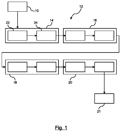
FIG. 1 illustrates one embodiment of the method of the invention;
FIG. 2 illustrates one embodiment of the system for implementing the method of the invention;
FIG. 3 illustrates deformation of a unit square with folding of space;
FIG. 4 is a two-dimensional illustration of a multi-scale iterative approach described in connection with the organic tissue registration step;
FIG. 5 illustrates cells inserted in the margin of discretization for two successive refining levels;
FIG. 6 illustrates a form function w;
FIG. 7 illustrates an exemplary approximation of a registration energy curve by a parabola;
FIG. 8 illustrates three steps of the approximation of the inverse registration function; and
FIG. 9 illustrates direct and indirect filtering steps.
A more detailed description will now be given of one embodiment of the registration method according to the invention. This registration method will be presented within the setting of an image processing method to estimate brain shift. However, this registration method is evidently fully independent of the processing method to estimate brain shift.
More precisely, the registration method of the invention: can be implemented for registering organic tissues other than the brain, and/or can be implemented in other types of image processing methods.
General Principle of the Processing Method to Estimate Brain Shift
As explained in the foregoing, the precise locating of a surgical target is essential to reduce morbidity rate during surgical excision of a brain tumour. When the size of the craniotomy is extensive, deformation of brain soft tissue may occur during the procedure. On account of this brain shift, preoperative data no longer correspond to the reality, and neuro-navigation is highly jeopardized.
With the present invention, it is possible to take this shift into account and to compute a corrected position of the brain's anatomical structures in order to locate ancillaries. Before surgical procedure on a patient's brain, a magnetic resonance angiogram (MRA) of the brain can be acquired. During the procedure, further to major brain shift, the surgeon carries out Doppler ultrasound scanning of the region of interest.
The processing method to estimate brain shift allows preoperative data to be updated in relation to brain shift occurring during the procedure. To do so, it is proposed to track the deformation of a particular anatomic structure i.e. the cerebral vascular tree, throughout the procedure. Owing to its distribution within the volume of the parenchyma, displacements of the vascular tree are representative of global tissue deformation.
The arteries and arterioles irrigating neural tissues lie both in the deep parts of the encephalon but also on the surface, and more particularly in the vicinity of the tumour whose development entails angiogenesis and hence the formation of new vessels. By locating the vascular tree relative to its initial position at the start of the procedure, it is possible to infer displacements of the vessels thereof caused by brain shift. This information, far from being dense within the global volume, remains localized to certain regions.
It is therefore proposed to use biomechanical modelling of the patient's brain to extrapolate global deformation on the basis of the displacement of the cerebral vascular tree. The global displacement field thus obtained is then applied to all the preoperative data for updating thereof.
Description of One Embodiment of the Method for Estimating Brain Shift
With reference to FIG. 1, different steps of the method for estimating brain shift are illustrated. The image processing method for estimating brain shift comprises the following steps: processing 100 a three-dimensional image of the patient's brain acquired before surgical procedure, to obtain a reference cerebral arterial tree of the patient, processing 200 two-dimensional images of the patient's brain acquired during the operation, for at least partial reconstitution of a current cerebral arterial tree of the patient, determining 300, from matching of the reference and current cerebral arterial trees, a deformation field of the vascular tree representing the displacement of the current vascular tree relative to the reference vascular tress, applying 400 the determined deformation field of the vascular tree to a biomechanical model of the patient's brain to estimate the global shift of the patient's brain; this model is used as mechanical interpolator to calculate all volume displacements inside the brain throughout the procedure, generating 500, from the estimated brain shift, at least one image of the patient's brain in which there is compensation for the brain shift.
Determining the Reference Cerebral Vascular Tree
As described in the foregoing, the method comprises a step 100 to process an image of the patient's brain acquired before the surgical procedure. The purpose of this processing is to locate the cerebral vascular tree in the image acquired before the surgical procedure. This cerebral vascular tree in the image, acquired before the surgical procedure corresponds to the vascular tree before shifting of the patient's brain, and will be called hereunder the "reference cerebral vascular tree".
Preferably, the image acquired before the surgical procedure is a three-dimensional image. Further preferably, this three-dimensional image is a magnetic resonance angiogram. Magnetic resonance angiography can reveal major contrast between tissues. Analysis of the magnetic resonance angiogram allows a precise distinction to be made between the types of tissues observed.
In particular the data it contains allows locating of the reference cerebral vascular tree. Also, the technique allowing the acquisition of a magnetic resonance angiogram has the advantage of being non-invasive and hence without danger for the patient, contrary to techniques which emit ionizing radiation for example such as tomography.
Once the patient is placed on the operating table, the processing of the three-dimensional image to obtain the reference cerebral arterial tree comprises a step to orientate the three-dimensional image relative to the patient's head. In other words, the spatial position of the reference vascular tree is determined relative to a reference frame of the patient's physical space. More precisely, the reference cerebral vascular tree is transposed to the patient's physical reference frame by means of a so-called rigid registration technique which is based on matching calibration points with their segmented equivalents in the magnetic resonance angiogram acquired before the operation.
Under the present invention by "rigid registration" is meant a geometric transformation consisting of a rotation and a translation. Computing can then be used to find the transformation between the two systems of coordinates.
The calibration points used may be points or salient anatomic surfaces such as the tip of the nose, supraorbital ridge, the surface of the cheeks or forehead. The calibration points may also be defined by a plurality of adhesive discs (at least three and preferably ten) positioned on the patient's skin before acquisition of the magnetic resonance angiogram. These discs are therefore acquired in the angiogram at the same time as the patient's brain.
The radiometric equivalents of the calibration points can be identified in the magnetic resonance angiogram. Once the patient is installed on the operating table, the surgeon indicates the position of each calibration point to a locating system by means of a probe. The locating system may be an optical locating system (for example comprising a stereoscopic camera) or a magnetic locating system or any other locating system known to persons skilled in the art.
Knowing the position of the reference cerebral vascular tree relative to the calibration points, and knowing the position of the calibration points once the patient is installed on the operating table, the system is capable of calculating the spatial position of the reference vascular tree relative to the spatial position of the patient. Registration between the images and the patient performed at the start of procedure allows the subsequent locating in the operative field of all the elements identified in the magnetic resonance image, and reciprocally to transpose the position of the ancillaries onto the volume of data in order to monitor and control the proper conducting of the surgical procedure.
Determination of the Current Cerebral Vascular Tree
The method further comprises a step 200 which comprises processing a plurality of two-dimensional images of the patient's brain, acquired during the operation, for at least partial reconstitution of a cerebral arterial tree called the patient's "current cerebral arterial tree". Throughout the surgical procedure, further to major brain shift of the patient, the surgeon acquires two-dimensional images.
Under the invention by "plurality of two-dimensional images" is meant 2D images within a determined (3D) volume, whose acquisition planes are secant or parallel. These 2D images can be obtained using any medical 2D or 3D image acquisition device such as 3D ultrasound images for example. Preferably, these two-dimensional images are ultrasound images acquired in Doppler mode, using a probe located by the locating system.
The ultrasound images in Doppler mode allow visualization of blood flows. Also the Doppler ultrasound technique has the advantage of being innocuous for the patient. Intra-operative Doppler ultrasound is therefore a good instrument for investigating brain shift during the procedure. This visualization mode is based on Doppler Effect and, by analyzing variations in the frequency of emitted ultrasound, allows tissue displacements to be located such as blood flows. The segmenting of these types of images is made easier on account of the colour coding used to represent flow velocities. With this modality it is therefore possible to visualize blood flows along the vascular tree within the volume of the encephalon, and thus to identify the position of the vessels which irrigate the parenchyma.
The acquisition of two-dimensional images is achieved as follows for example. The located probe is contacted with the patient's brain through the craniotomy made by the surgeon. A rotational movement is manually imparted to the located probe so that the ultrasound plane scans the largest possible part of the brain around the tumour.
The located probe comprises a marker enabling the locating system to define its position and orientation relative to the patient's physical reference frame, and hence to reposition the two-dimensional images spatially within the patient's physical reference frame. After the acquisition of a series of two-dimensional images, these are processed to locate the patient's current cerebral vascular tree. More precisely, the centres of the vessels contained in each two-dimensional image are selected so as to obtain a point cloud. This point cloud at least partly represents the patient's current cerebral vascular tree.
Registering the Reference and Current Vascular Trees
At another step 300 of the method, the reference and current vascular tree are matched to determine a deformation field representing the displacement of the current vascular tree relative to the reference vascular tree. More specifically, the reference vascular tree is registered with the current vascular tree.
By "elastic registration" is meant the determination, from datasets which represent two digital images of one same region, of a transformation allowing mapping between the reference image and current image. In other words, it entails "best" overlaying of the structures contained in two comparable images. The data derived from the three-dimensional image and from the two-dimensional images are of different type.
On one hand, the reference vascular tree obtained from pre-operative data is practically continuous, the entire patient's head is contained within the volume of data, and segmenting does not so to speak generate any artefacts in the reconstruction of the cerebral vascular tree. On the other hand, the current vascular tree obtained from intra-operative two-dimensional images is composed of a point cloud, and these two-dimensional images only cover a fraction of the volume of the brain. Depending upon the skill of the operator, the two-dimensional images may be more or less regularly distributed in space, some regions comprising multiple acquisitions whilst others do not contain any acquisition.
The task incumbent at registration step 300 of the cerebral vascular trees is therefore to estimate an elastic transformation between: the current intra-operative configuration of the vascular tree defined by a scattered, redundant, incomplete and noisy point cloud, and the reference configuration defined by complete noise-free data obtained from pre-operative imaging. The deformation field is then computed from the correspondence determined between the reference vascular tree and the current vascular tree. The origin of each vector of the deformation field is a point of the reference vascular tree and designates a deformed point of the current vascular tree.
Elastic registration is guided by minimizing registration energy. This registration energy quantifies the similarity between the current vascular tree and the reference vascular tree. Optimal registration is achieved with zero registration energy. The objective of the elastic registration step is iteratively to minimize the value of this registration energy by causing the points of the current vascular tree to move towards the points of the reference vascular tree.
The rapidity of computing is obtained by means of: prior computing of a distance map--between each point of the current vascular tree and its counterpart in the radiometric sense (i.e. the point which designates the same structure) in the reference vascular tree--on which evaluation of the registration energy is based, and determining the direction of the steepest descent computed on each iteration of the minimization process.
Given the scattered and irregular nature of the data, the search for an elastic registration function must be constrained so as not to arrive at an aberrant registration. The elastic registration function is a non-linear transformation allowing mapping from the current vascular tree to the reference vascular tree. More precisely, the conditions related to the type of data it is desired to register are determined to guarantee heed of essential physical criteria.
Since the data concerns organic data, one first condition which must be met by the elastic registration function is non-folding of space. Shifting of the patient's brain cannot induce folding-over of the patient's brain.
A second condition which must be met by the elastic registration function concerns the continuity of deformation propagation. The reference and current vascular trees are observations of the physical phenomenon of brain shift. Similar to the process of brain shift in the patient, without tearing or resection of tissue, the registration function must be continuous and even continuously differentiable i.e. differentiable at every point of the domain and not having any differential discontinuity.
A third condition which must be met by the registration function is that two different points of the current vascular tree cannot have the same image in the reference vascular tree, and vice versa. The elastic registration function such as proposed in the invention has the advantage of being invertible with the desired degree of accuracy. Once this registration function has been computed, post-processing of the result produced by registration allows the elimination of aberrations due to the presence of noise in the data of the intra-operative two- or three-dimensional images.
All the displacements of the vascular tree that are finally selected form a deformation field representing displacement of the current vascular tree relative to the reference vascular tree. The reader will appreciate that the registration step can be applied to the registration of structures other than a cerebral vascular tree. In particular, the elastic registration presented above can be applied to the registration of any type of organic tissue.
Extrapolation of the Deformation Field of the Cerebral Vascular Tree to the Entire Volume of the Organ via a Biomechanical Model
At another step 500 of the method, the determined deformation field of the vascular tree is applied to a biomechanical model of the soft tissues of the patient's brain to estimate the global shift of the patient's brain. This mathematical model formalizes a priori knowledge of the behaviour of the organ, and allows the global behaviour thereof to be inferred under local deformation constraints deduced from intra-operative observation, called boundary conditions.
The biomechanical model (also known as deformable model) plays a twofold role. First, the biomechanical model allows extrapolation of displacements of the vascular tree to the entire volume of the brain to simulate the effect of brain shift.
Second, the biomechanical model allows data adjustment. The estimation of the deformation field of the vascular tree is flawed with errors due to the imaging mode used, to the limitations of segmenting algorithms and to those of elastic registration computing in order to match the current vascular tree with the reference vascular tree. With the biomechanical model it is possible to harmonize the deformation field by deleting errors in the input data to the biomechanical model. This renders the method resistant to artefacts present in noisy data collected during the surgical procedure (i.e. the two- or three-dimensional ultrasound images).
The originality of the method therefore lies in the complementarity between a biomechanical model approximating the patient's cerebral tissue behaviour and tracking of a potentially noisy anatomical structure but representing brain shift by means of the cerebral vascular tree. On completion of step 500 of the method, the patient's global brain shift is estimated. A last step 600 of the method, and using the estimated global brain shift, concerns the generation of at least one image of the patient's brain in which there is compensation for brain shift. For example, this image is the three-dimensional image (or two-dimensional cross-sectional images of this three-dimensional image) acquired before the operation to which the patient's global estimated brain shift is applied so as to update pre-operative data in relation to the patient's estimated global brain shift.
Verification of the Coherency of Computed Deformation
Advantageously, the method may comprise a step to compute discrepancies between points in the generated image of the brain and one or more control two-dimensional images acquired during the operation. This enables the user to verify the coherency and accuracy of the computing performed by the above-described method. For this purpose, the user may for example acquire one or more control two-dimensional images of the patient's brain to compute the positioning error between the points of the control two-dimensional images and their counterparts in the image generated from the patient's estimated global brain shift.
For example, the user may scan the cerebral tissues in the region of interest whilst projecting the position of the vascular tree deformed by the model onto the control two-dimensional images. The overlaying of the two data items i.e. real-time Doppler obtained by scanning the organ, and simulated Doppler signal computed from the incidence of the located ultrasound slices relative to the vascular tree deformed by the system, enables the user to evaluate coinciding between the model and patient reality. The assessment of deformation quality allows the user to take a decision on whether or not to follow the indications of the system on the basis of the updated pre-operative data.
Since brain shift is a changing process, this validation is made immediately after the acquisition of the data on which the deformation algorithm is based, to guarantee the pertinence thereof. The above-described method is fully adapted to continuous monitoring of brain soft tissue deformation, both through its response times which are of the order of a few seconds, and through the repeatability of the data acquisition procedure which does not require any major interruption during surgical procedure or the providing of cumbersome equipment.
Theory Associated with Elastic Registration
A more detailed description will now be given of the theory associated with the elastic registration step. The explanations below are given in connection with the elastic registration of the cerebral vascular tree, but evidently this registration can be applied to other types of organic tissues.
Elastic registration is an application R:.sup.3.fwdarw..sup.3, which minimizes a certain error of registration, or rather more a registration energy defined between a set of source points S and another set of target points D. Registration energy R is the measurement of a "similarity" between the set of transformed points R(S) and the target set (D). When the two sets merge then this energy becomes zero and registration is achieved. If the registration energy and the function space in which the transformation R takes place are not correctly defined, then the problem of finding an optimal R is ill-defined i.e. the existence and unity of R are not guaranteed.
In this part we will describe the framework for computing elastic deformation which allows robust establishment of elastic correspondence between the data under consideration. The specificities of this approach lie in the mathematical properties of transformation R, shown further on, which guarantee the physical realism thereof.
Registration Energy
Registration energy can be freely defined to reflect the type of registration problem concerned. For example for registration between two images, this measurement can be based on the differences between the pixel or voxel values of the source and target images. In the case in hand, the similarity between the datasets S and D is defined by the spatial proximity of the two point clouds. Without any other knowledge of the type of data being handled, it is possible for example to define registration energy E.sub.reg as the mean of the minimum Euclidian distances between R(S) and D.
.function..function..times..di-elect cons..times..function..function..function..times..di-elect cons..times..function..function. ##EQU00002## where: R represents the elastic registration function, Card(S) is the cardinal of the source set S, Card (D) is the cardinal of the target set D, d(R(s),D) represents the distance between set D and the transform by R of a point s in set S, d(d,R(S) represents the distance between a point d of set D and the transform by R of set S.
In this case, optimal registration is achieved when the value of E.sub.reg cancels itself out. The symmetric energy presented above assumes that each structure present in S can, by means of a suitable transformation R, find a match among D, and reciprocally. The designations "S" and "D" of the two datasets are interchangeable.
In the case in hand however, the structures present in S and D may not be equivalent and the assumption of symmetry does not hold since the structures in S only represent a sub-set of D. An alternative definition must be found to take this into consideration. Henceforth, "S" shall designate all the points defining the current, intra-operative configuration of the vascular tree, and D shall designate those which define the pre-operative reference configuration thereof. The elastic registration function R is therefore the function which maps the points of S to D, and an asymmetric definition of the energy of this registration can be formulated by truncating the above symmetric expression:
.times..times..function..times..di-elect cons..times..function..function. ##EQU00003##
The meaning of the names "source" and "target" can be better grasped by viewing elastic registration as an iterative process in which the source points S are moved towards the target set along an optimal trajectory on a surface of potential energy whose relief is defined by the spatial configuration of the points in D. The evaluation of a candidate configuration R(S) is made on the set containing fewer data, whilst the energy function is more strictly defined by D which contains the reference information on the entire structure of the vascular tree. Alternative solutions to the problem of asymmetry can be found in the literature. The above definition of E.sub.reg can lead to situations in which a group of source points is registered to a confined part of D, in other words this energy does not promote distribution of the point sources over the target structure. To avoid this situation, it is possible to extend its expression by adding a term which quantifies this distribution but which operates solely in a restricted neighbourhood of D points which contain R(S) points.
Finally, since the cardinal of set S does not change throughout registration, it is also possible to simplify the preceding expression of energy E.sub.reg by eliminating its preceding multiplicative constant, which leads us to the following definition of E.sub.reg:
.function..di-elect cons..times..function..function. ##EQU00004##
Space of Deformation Functions
Given the scattered, irregular nature of the data, the search for an elastic registration function must be constrained so as not to arrive at an aberrant registration. This pitfall is chiefly due to numerous local minima scattered over the product of the energy function for a given D configuration. The two sets S and D are observations of the physical phenomenon being examined i.e. brain shift.
It is therefore assumed that in similar manner to the brain shift process, without any tearing or resection of tissue, the non-linear transformation R being sought is continuous and even continuously differentiable i.e. differentiable at every point of the domain and does not exhibit any differential discontinuity. This defines a first restriction on the search space of the registration functions: R.epsilon.C.sup.1(.sup.3).
A further strong constraint on the nature of the transformation is that it must not entail folding of space. The non-folding constraint can be mathematically expressed as follows. Let us consider a trihedron oriented positively consisting of three infinitesimal vectors dX.sub.1, dX.sub.2 and dX.sub.3 placed at a point p of the space. Let dV denote the positive volume defined by these three vectors and whose value is given by the determinant of the matrix formed by the three vectors. dV=(dX.sub.1.times.dX.sub.2)dX.sub.3=|dX.sub.1dX.sub.2dX.sub.3|
After application of R transformation at point p, the three vectors are transformed to dx1, dx2 and dx3. The infinitesimal nature of these vectors allows the following approximation:
.A-inverted..differential..differential..times..times. ##EQU00005## The volume defined by the transformed trihedron, denoted dv, is then obtained in similar manner:
.differential..differential..times..times..function..times. ##EQU00006##
The non-folding constraint is then quite simply written: dv>0. This means that the deformed infinitesimal volume has not been "folded over" (dv<0) by R or fully crushed (dv=0). Therefore the application of R does not locally fold over space if and only if its Jacobian at p is strictly positive. In our case, elastic registration must not fold space at any point, which leads to the expression of the non-folding constraint: .A-inverted.p.epsilon..sup.3,|J.sub.R(p)|>0
If, at a given point, the Jacobian is greater than 1, this means that the elastic registration locally stretches the volume; if, on the contrary, it is smaller than 1, then the volume is contracted. Finally, the product of the Jacobian matrix of R computed at a point by a unit vector gives us the stretching or contraction rate of the space in a given direction in the neighbourhood of this point. FIG. 3 shows the deformation of a unit square with folding of space.
Finally, for the same physical reasons, the application R must be injective. This translates as the fact that two separate points cannot have the same image by R, and physically R must not bring two atoms to one same point in space. If R is an injection, then for each point reached p.epsilon.Image(R), a predecessor can be computed.
In the case in hand in which S represents a fraction of the structure present in D, the transformation that is sought in fine is the one which brings D to S, i.e. R.sup.-1, in order to map the deformation field of the vascular tree in the reference configuration D to the current configuration S as described above. For the expression R.sup.-1 to have a meaning, we need D.OR right.Image (R). To simplify these considerations, it is considered that the R functions are surjective i.e. such that Image (R)=.sup.3 it is therefore possible to conclude that the registration function R that is being sought is bijective.
The non-folding constraint guarantees that the Jacobian is strictly positive at every point of .sup.3, yet this is insufficient to guarantee global bijectivity. The function space must therefore be suitably defined to ensure the bijectivity of function R. The following sections describe the registration strategy adopted to arrive at minimization of registration energy whilst paying heed to the above-mentioned constraints of differentiability, non-folding and bijection.
Computing of Registration
The approach presented here is inspired by mechanical modelling of solids based on discretization of finite-element type. To approximate the mechanical behaviour of non-structured data, it is assumed that the point cloud subjected to deformation is encompassed in a virtual elastic solid. Since displacement of the points translates the physical properties of an underlying structure whose geometry is unknown, the shape of a box surrounding the points is arbitrarily given to this virtual solid. All admissible deformations are then defined as the successive combinations of elementary deformations of the encompassing solid, whose effects are propagated throughout its volume and modify the position of the inner points. The elementary deformations mentioned here are defined later on. This described 3D registration technique can easily become a 2D registration technique by replacing the notion of "virtual solid" by "virtual plane". The illustrations presented below are based on a 2D implantation of registration for clarification of the concepts thereof.
The elastic registration function is assembled iteratively so that the registration energy E.sub.reg is optimally reduced with each step. Let S.sub.0:=S denote the initial cloud of source points, and let S.sub.i be the cloud of source points obtained after the iteration i. The domain of the virtual solid is discretized with a certain level of refining into regular hexahedrons (or squares, in 2D) called "cells". The elementary deformations of the solid are obtained by individually displacing the nodes of the mesh thus formed.
The uniting of the cells surrounding a node n defines its "neighbourhood" denoted V (n). An elementary registration function r is defined by propagating the displacement of the node n to all the points of .sup.3 under the following constraints:
.times..times..times..times..times..times..times..times..times..times..ti- mes..times..differential..function..times..times..times..times..A-inverted- ..di-elect cons..differential..function..function..times..times..times..ti- mes..times..times..times..times..times..times..times..times..times..times.- .function..function..function..times..times..times..times..times..times..t- imes..times..times..times..times..times..times..times..times..A-inverted..- function..function. ##EQU00007## Each node of the discretized solid is given consideration and the gradient of the registration energy, as a function of displacement of the node, is computed. The opposite of this vector defines the preferred displacement of this node i.e. the displacement which, when applied to the node, leads to the greatest reduction in registration energy.
Of all the nodes, the node which allows the greatest reduction in gradient is chosen and its preferred displacement is applied to it whilst the other nodes remain immobile. Local deformation of the solid is computed by propagating the displacement of the node through its neighbourhood, and the position of the source points it contains is modified accordingly, thereby giving the new configuration of the point cloud Si+1.
Once the elementary deformation has been applied, the solid returns to its initial configuration, at rest, and the source points Si+1 are distributed within its volume. A new iteration can then be computed using the new configuration Si+1 as starting point. The iterations finally come to an end when no significant reduction in energy can be obtained by displacing the nodes of the mesh of the solid.
The description continues in the full USPTO document.
About 6,033 words. The USPTO PDF has it with every drawing.
Fees are due 3.5, 7.5 and 11.5 years after grant. This patent expired on May 13, 2026, so the fee marked "not paid" was the one that went unpaid.
METHOD FOR REGISTERING A SET OF POINTS IN IMAGES
Filed Oct 2009 · published Jul 2011Method for registering a set of points in images
Filed Oct 2009 · granted May 2014Earlier publications, parents and continuations. None of them can still be enforced, or this patent would not be listed.
Prior art cited by the examiner or applicant. Useful when you check your own idea for novelty.
Everything on this page comes from the documents linked above.