 Lapsed, fee not paid5 drawings
AI & Machine Learning · US 8,724,858 B2
Driver imaging apparatus and driver imaging method
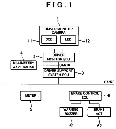
An imaging mechanism captures an image of a face of a driver of a vehicle.
US 8,724,865 B2 · Assignee: Medical Metrics, Inc. · Inventors: Hipp; John A. et al.
Sheet 1 of 15 from the published document. All sheets in the USPTO PDF
A method computer program for displaying relative movement between vertebrae or other medical objects is provided. The method generally includes acquiring at least two images of adjacent vertebrae, wherein the at least two images are acquired from a substantially similar acquisition position and illustrate the vertebrae in two different positions. The method further includes displaying a first image to a user on a screen, displaying a second image to the user overlaid onto the first image, translating, via user input, the first or second image to align a stationary feature present in both the first and second images, and alternately displaying the translated first and second images to display relative movement between the stationary feature and adjacent features.
The present embodiments relate to clinical assessment of spinal stability, and more particularly, to a method and system for tracking, stabilizing, and reporting motion between vertebrae. One of the primary functions of the spine is to protect the spinal cord and associated neural elements, as well as, mechanically support the upper body so that a person can perform the desired activities of daily living. When these mechanical functions are compromised by trauma, disease, or aging, the individual can experience pain and other symptoms. Millions of people suffer from disorders of their spine. Back disorders are a leading cause that prevents individuals from working productively in society. As part of the diagnosis and treatment of these individuals, clinicians need to know if the motion in the spine is abnormal. The spine consists of 26 bones call vertebrae. Vertebrae are normally connect
1 of 15 drawing sheets so far from the published document, cropped to the drawing. Every sheet is in the USPTO PDF.
What the patent claimed, word for word. All of it is now free to use.
The present embodiments relate to clinical assessment of spinal stability, and more particularly, to a method and system for tracking, stabilizing, and reporting motion between vertebrae.
One of the primary functions of the spine is to protect the spinal cord and associated neural elements, as well as, mechanically support the upper body so that a person can perform the desired activities of daily living. When these mechanical functions are compromised by trauma, disease, or aging, the individual can experience pain and other symptoms. Millions of people suffer from disorders of their spine. Back disorders are a leading cause that prevents individuals from working productively in society. As part of the diagnosis and treatment of these individuals, clinicians need to know if the motion in the spine is abnormal.
The spine consists of 26 bones call vertebrae. Vertebrae are normally connected to each other by a complex arrangement of ligaments. A large number of muscles also attach to these vertebrae and create motion required by the individual. Vertebrae have complex geometries and are separated from each other by a structure called the intervertebral disc. Several research studies have shown that if vertebrae are fractured, if ligaments between vertebrae are damaged, or the intervertebral disc between vertebrae is damaged, then the motion between the vertebrae can be altered. When diagnosing and treating a patient with a spinal disorders clinicians need to know if motion between vertebrae is abnormal or not, since any abnormalities in motion can help the clinician understand what part of the spine has been damaged.
Clinicians use physical tests and imaging studies to determine if motion in the spine is abnormal. The ability to correctly identify abnormalities in motion (the sensitivity), and the ability to correctly determine that there is no abnormality (the specificity) of most common clinical tests are either not known, or have been shown by scientific studies to be unreliable or inaccurate in many patients. One of the most common clinical imaging studies used to assess motion in the spine is simple radiographs. In some cases, the clinician compares radiographs taken with the person in two or more different positions, to assess motion in the spine. A single static image can show if there is any misalignment of the spine, but the single image cannot be used to determine if there is abnormal motion in the spine. Comparing radiographs taken of the patient in two or more positions can be difficult and scientific studies have shown this technique to have significant limitations.
To be of clinical value, a diagnostic test must be reliable, easy to interpret, and ideally should be non-invasive and relatively fast. Currently, the most accurate method for measuring motion between vertebrae in living subjects, is to surgically implant metal markers into the vertebrae. The technique is commonly referred to as Roentgen Stereophotogrammetric Analysis (RSA). With RSA, radiographic images are obtained with the patient in two or more different positions. The radiographic images must be taken with the patient located within a geometric calibration frame that allows the spatial coordinates of the images to be calculated. The position of the metal markers can then be measured and compared between images. Radiographs are also usually taken in two different planes, allowing for three-dimensional motion measurements. Although this method can be accurate, it is invasive because it requires surgical implantation of markers. In addition, it is time consuming to analyze the image to measure motion of the markers. Although, this method has been used in laboratory and clinical research studies, it is not known to be used in routine clinical practice.
Another method that has been used to measure motion between vertebrae in the spine involves combining geometric information obtained from a computed tomography (CT) study of the spine with information from a fluoroscopic imaging study of the spine. By knowing the actual three-dimensional geometry of an object, it is possible to estimate two-dimensional motion from fluoroscopic imaging data. Although this method is non-invasive, it does require a CT examination and substantial post-processing of the data. It is not a method that could be readily used in routine clinical practice. However, this method has been used in several published laboratory studies, mostly related to motion around total joint replacements.
Accordingly, a reliable and accurate method to assess motion in the spine that can be used in clinical practice for overcoming the problems in the art is desired. Such a method could also be useful in research studies to develop better methods for diagnosing and treating patients with spinal disorders.
According to one embodiment of the present disclosure, a method for processing medical images via an information handling system identifies and tracks motion between vertebrae of a spine. The method includes identifying one or more vertebra in each of at least two medical images accessed via the information handling system, and acquiring tracking data as a function of a position of the respective identified vertebrae from the at least two medical images. The method also includes processing a sequence of the at least two medical images as a function of the tracking data to track a motion between the vertebrae of the spine in the sequence.
The present disclosure is best understood from the following detailed description when read in conjunction the accompanying Figures. It is to be noted, however, that the accompanying Figures illustrate only exemplary embodiments of the invention and are therefore not to be considered limiting of its scope, for the invention may admit to other equally effective embodiments.
FIG. 1 is a functional block diagram view of an information handling system configured to measure and display intervertebral motion in the spine according to one embodiment of the present disclosure;
FIG. 2 is a block diagram view of various components for the processing of medical imaging data to calculate an intervertebral motion according to one embodiment of the present disclosure;
FIG. 3 is a graphical user interface view of an example interface configured to enable a user to select sequences of medical images for the purposes of tracking or visualizing motion between vertebrae according to another embodiment of the present disclosure;
FIGS. 4a and 4b are illustrative example radiographic images of the spine showing a search model region (the square in the image of FIG. 4a) with selected areas masked-out and the anatomic landmarks (in the image of FIG. 4b) that would be associated with the model;
FIG. 5 is a flow diagram view of decision making to either create a new model or use an existing model in the method according to one embodiment of the present disclosure;
FIG. 6 is a block diagram view of the steps and tasks for tracking multiple images from a sequence of images according to one embodiment of the present disclosure;
FIG. 7 is an example graphical user interface view configured to allow a system user to adjust search parameters used during tracking of a vertebrae in a sequence of medical images;
FIG. 8 is a diagram view illustrating how the position of an object being tracked can be anticipated (N+1) based on data describing where the object was in the previous frames (N and N-1);
FIG. 9 is an illustrative plot in connection with using the Hough Transform for finding a straight line through a set of discrete points, for example, according to one embodiment of the present disclosure;
FIGS. 10a and 10b are illustrative plots of possible (r, theta.) values defined by each known point in FIG. 10a that are mapped to curves in the Hough parameter space of FIG. 10b;
FIGS. 11a and 11b are illustrative image views of example radiographic images of the spine show in FIG. 11a with an initial contour drawn by a user around a vertebrae and a final contour in FIG. 11b subsequent to an application of a method of snakes used to obtain a more refined representation of the vertebral boundaries;
FIGS. 12a and 12b are illustrative image views of example radiographic images of the spine showing the affect of edge detection before masking and after masking to identity the contours of a vertebra, wherein the first image shows the contours before masking (FIG. 12a) and the second image (FIG. 12b) represents the contour that would be used for a geometric searching via the Generalized Hough Transform in subsequent images;
FIG. 13 is graphical user interface view of an example interface showing how a range of images from a larger sequence of images can be selected for the purposes of tracking over a user specified portion of the images;
FIG. 14 is a graphical user interface view of an example user interface that allows a user to play back and review images of the spine in motion, with, or without feature stabilization active, wherein feature stabilization uses the results of tracking of a vertebrae to make the selected vertebrae remain in a constant location on the screen as the multiple images are displayed;
FIG. 15 is a schematic diagram view of a spine in two positions before tracking, as well as the stabilized image view wherein one of the vertebra is in a constant position, allowing relative displacements of adjacent vertebrae to be clearly seen;
FIG. 16 is a graphical user interface view of an example of how the quantitative results of the tracking of a vertebra can be displayed to the user; and
FIG. 17 is an illustrative view of a report according to one embodiment of the present disclosure.
It is to be understood that the following disclosure describes several exemplary embodiments of the invention, along with exemplary methods for implementing or practicing the invention. Therefore, the following disclosure describes exemplary components, arrangements, and configurations that are intended to simplify the present disclosure. These exemplary embodiments are merely examples of various possible configurations and implementations of the invention and are not intended to be limiting upon the scope of the invention in any way. Further, the present disclosure may repeat reference numerals and/or letters in the various exemplary embodiments and across multiple Figures. Applicants note that this repetition is for the purpose of simplicity and clarity and does not in itself dictate a relationship between the various exemplary embodiments and or configurations discussed herein. Additionally, where the following disclosure describes structural relationships between the elements of a particular embodiment, the particular structural relationship described is not intended to be limiting upon the scope of the invention, as the inventors contemplate that various components may be interstitially positioned without departing from the true scope of the invention. Similarly, where method steps are described, unless expressly stated herein, the invention is not intended to be limited to any particular sequence of the method steps described. Further, the invention is not intended to be limited only to the method steps described, as various additional steps may be implemented in addition to the described method steps without departing from the true scope of the invention.
Additionally, in various embodiments, the invention may provide advantages over the prior art; however, although embodiments of the invention may achieve advantages over other possible solutions and the prior art, whether a particular advantage is achieved by a given embodiment is not intended in any way to limit the scope of the invention. Thus, the following aspects, features, embodiments, and advantages are intended to be merely illustrative of the invention and are not considered elements or limitations of the appended claims; except where explicitly recited in a claim. Similarly, references to "the invention" herein should neither be construed as a generalization of any inventive subject matter disclosed herein nor considered an element or limitation of the appended claims, except where explicitly recited in a claim.
Further, at least one embodiment of the invention may be implemented as a program product for use with a computer system or processor. The program product may define functions of the exemplary embodiments (which may include methods) described herein and can be contained on a variety of computer readable media. Illustrative computer readable media include, without limitation, (i) information permanently stored on non-writable storage media (e.g., read-only memory devices within a computer such as CD-ROM disks readable by a CD-ROM drive); (ii) alterable information stored on writable storage media (e.g., computer disks for use with a disk drive or hard-disk drive, writable CD-ROM disks and DVD disks, zip disks, portable memory devices, and any other device configured to store digital data); and (iii) information conveyed across communications media, (e.g., a computer, telephone, wired network or wireless network). These embodiments may include information shared over the Internet or other computer networks. Such computer readable media, when carrying computer-readable instructions that perform methods of the invention, may represent embodiments of the present invention.
Further still, in general, software routines or modules that implement embodiments of the invention may be part of an operating system or part of a specific application, component program, module, object, or sequence of instructions, such as an executable script. Such software routines typically include a plurality of instructions capable of being performed using a computer system or other type or processor configured to execute instructions from a computer readable medium. Also, programs typically include or interface with variables, data structures, etc., that reside in a memory or on storage devices as part of their operation. In addition, various programs described herein may be identified based upon the application for which they are implemented. Those skilled in the art will readily recognize, however, that any particular nomenclature or specific application that follows facilitates a description of the invention and does not limit the invention for use solely with a specific application or nomenclature. Furthermore, the functionality of programs described herein may use a combination of discrete modules or components interacting with one another. Those skilled in the art will recognize, however, that different embodiments may combine or merge such components and modules in a variety of ways.
The present embodiments provide assistance to system users in measuring and visualizing motion between vertebrae in the spine. In one embodiment, the method is implemented via an information handling system. The information handling system can include one or more of a computer system 1 running appropriate software (as further described herein), data input devices 2a-b, a keyboard 3, a pointing device or tool 4, a display 5, and output devices such as printers 6, a computer network 7, and disk or tape drives 8, as shown, for example in FIG. 1.
Referring to FIG. 2, a basic flow of the process 10 according to one embodiment of the present disclosure includes one or more sub-processes, referred to herein as engines. In one embodiment, the method includes capturing images via an image capture engine 11 or importing data from a medical imaging system via an image import engine 12. An image organization and database engine 13 is configured to provide image organization and database storage as appropriate for a given situation or clinical application. Responsive to receiving captured and/or imported data, the system proceeds through a process of tracking individual vertebrae via an image tracking engine 14, automatically or manually, for example, per request of a system user. At the completion of tracking, the system creates one or more reports, automatically or manually in response to a user request, the one or more reports describing motion between tracked vertebrae via reporting engine 15. Alternatively, at the completion of tracking, a system user can use the system to review the images via image review engine 16. In either the generation of the report or the reviewing of images, the same can be performed with, or without feature stabilization in use or operation. The various engines will be described in further detail herein below.
According to one embodiment an information handling system is programmed with computer software to implement the various functions and functionalities as described and discussed herein. Programming of computer software can be done using programming techniques known in the art.
As discussed herein, the method for tracking vertebrae in a sequence of medical images is implemented using a computer system. The computer system can include a conventional computer or workstation having data input and output capability, a display, and various other devices. The computer runs software configured to calculate and visualize intervertebral motion automatically or manually according to desired actions by a system user, as discussed further herein below.
Referring again to FIG. 2, the image capture engine 11 and or image import engine 12 provide mechanisms for getting image data into the system. Data can be transferred to the system via a computer network video or image acquisition board, digital scanner, or through disk drives, tape drives, or other types of known storage drives. After transferring data to the computer system, the method of importing and organizing the image data is implemented via an image organization and database engine 13. This can be accomplished through a user-interface 19 (FIG. 3) that allows the user to enter a new patient and associated information, and implements a study selection list containing a list of studies in the database that are available for analysis or review. The study list is constructed during application start-up by scanning the database for all available studies. For each study listed in the database, an entry will appear or be made in the list of studies on the user interface. During system operation, the user may click on any study in the list to load the corresponding study.
The magnification of the images must be known in order to calculate relative motions between vertebrae in real-world units. In digital medical images, the magnification is usually described by the pixel size, which is the dimensions of each picture element (pixel) in units of millimeters or other defined unit of length. If images are acquired directly into the computer system, the magnification of the imaging system must be known and input to the system. If images are imported, the magnification can either be determined from information in the header of the image data file, or can be defined by the user.
Many current medical images are in DICOM format, and this format usually has information in the header regarding the pixel size. If not, the user can be prompted to draw a line, or identify two landmarks, and then give the known, real-world dimensions of the line or between the points. The pixel size is then calculated as the number of pixels between points or the length of the line in pixels divided by the known length. A third alternative is to allow the user to directly specify the pixel size. A fourth alternative is to place an object with a unique geometry and known dimensions next to the spine when it is imaged. In the latter instance, the object can then be automatically recognized when importing the images, allowing for automated image scaling.
One goal of the embodiments of the present disclosure is to track the position of a specific vertebra in a sequence of medical images. Accurate tracking relies on rich texture, defined as wide variation in gray levels within and particularly at the boundaries of the vertebra being tracked. Sometimes it's necessary to enhance the features of an image to create greater contrast, better definition of vertebral edges, or reduce noise in the search model and/or target images.
One approach is to apply an image processing technique called `Histogram Equalization`. Histogram equalization creates gray-level variations within regions that appeared more uniform in the original image, and has the effect of non-linearly enhancing certain details (i.e. making dark areas darker and light areas lighter). Histogram equalization involves first creating a histogram describing how many pixels are at each of the possible values. A transformation function is then applied to the pixels values that uses the histogram to spread the pixel values over a greater range of pixel values. A variation of histogram equalization is a technique called Histogram Stretching or matching which re-maps all gray levels to a full dynamic range based on a user specified distribution function.
For tracking vertebrae in medical images, histogram equalization or stretching can be done over a user selected range of gray-scale values or can be weighted in a particular manner to exclude or correct specific image artifacts, such as blooming in fluoroscopic images. A third technique for improving image quality implements a gamma curve that non-linearly expands the range of gray levels for bone while suppressing the range of gray-levels for soft tissue. For tracking of medical images of the spine, a wide variation in the gray-levels corresponding to bone is most desirable because bone is usually the object being tracked.
Alternative techniques that can be used to improve the quality of the tracking, by enhancing the variation in grey levels in and around vertebrae, include: 1) contrast Limited Adaptive Histogram Equalization (CLAHE), 2) Low-pass or high-pass filtering, 3) Thresholding, 4) Binarization, 5) Inversion, 6) Contrast enhancement and 7) Fourier transformation. These techniques are described in Gonzalez R C, Woods R E. Digital Image Processing, 2nd edition. Prentice Hall, Upper Saddle River, N.J. 2002 which is incorporated by reference.
Tracking of vertebrae in medical images can also be improved through the application of certain edge detection algorithms. Edge detection and/or edge enhancement algorithms that can improve the tracking of vertebrae in medical images include; gradient operators (such as Sobel, Roberts, and Prewitt), Laplacian derivatives, and sharpening spatial filters, as defined in Gonzalez R C, Woods R E. Digital Image Processing, 2nd edition. Prentice Hall, Upper Saddle River, N.J. 2002 which is incorporated by reference. These algorithms alter the original image to make the edges of objects in the image appear to be more distinct and can improve the accuracy and reliability during tracking of vertebrae in certain types of medical images.
According to one embodiment, the computer system is programmed via suitable software to provide easy access to a range of image enhancement and edge detection algorithms. The image enhancement and edge detection algorithms allow for tracking of a much wider range of images, image qualities, and object features. To reduce noise in fluoroscopic images in particular, if many images have been taken of the spine during a motion maneuver, there can be little motion of the spine between immediately adjacent frames. In that case, adjacent images can be averaged together to create a new image sequence. Averaging together of adjacent images can significantly reduce noise in the images.
After importing or acquiring image data, and improving the quality of the images, the next step in analyzing intervertebral motion is to track the motion of individual vertebra. Tracking is the process of determining the precise position and orientation of an object in two or more (usually many) images. FIGS. 4a and 4b are illustrative example radiographic images of the spine showing a search model region (the square 17 in the image of FIG. 4a) with selected areas masked-out, and the anatomic landmarks (indicated by reference numeral 18 in the image of FIG. 4b) that would be associated with the model.
FIG. 5 is a flow diagram view of decision making to either create a new model or use an existing model in the method according to one embodiment of the present disclosure. Automated, or semi-automated tracking uses a search model 20 (FIG. 5). The search model represents the image characteristics (geometry and density variations) of the specific vertebra or object (implant, pathologic feature, etc) being tracked. With respect to the tracking of vertebrae in radiographic (x-ray) images, this technique involves identifying a small region 17 within a source image (FIG. 4a) that contains the vertebra or object of interest. This region containing the object to track is called a search model or template. The search model is used to find similar regions in subsequent `target` images that contain identical information as the model 20 (FIG. 5).
Models also may have specific anatomic landmarks 18 associated with the model, such that the geometric relationship between the model and the landmarks is defined (FIG. 4b). The search model is used to find the best match by interrogating each image in a sequence of images to locate the position and orientation of the model that yields the best match with the object being tracked. It is possible to either define a new model or use an existing model 20 (FIG. 5). The user is first prompted at 21 to either use an existing model or build a new one. If the user chooses to use an existing model, the chosen model is retrieved at 22. If the user chooses to build a model, then a model is built at 23. The method further includes applying the model to the images to generate tracking data at 24.
Identification of the vertebrae to be tracked also is used to establish the frame of reference for relative motion calculations. The frame of reference can be defined by the user selection of 3 or more landmarks which define a Cartesian coordinate system. Alternatively, the frame of reference can be defined by the user drawing 2 or more lines which in turn define a Cartesian or Polar coordinate system Identification of the vertebrae to be tracked can be accomplished by drawing a region of interest around the vertebrae. Identification of the region of interest (ROI) can also be done manually by the operator, by tracing the boundaries of the ROI, or defining the ROI by a box, circle or other simple geometric shape.
Identification of the vertebrae to be tracked can also be computed from anatomic landmark points identified by a system operator, or the identification of the region of interest can be accomplished by a user identified point in or near the vertebra, or with the computer, using various segmentation algorithms to identify the entire region of interest. Automated identification of the features to be tracked can also be accomplished by various segmentation algorithms, for example, that can include thresholding, seed growing, or snakes, as defined in Gonzalez R C, Woods R E. Digital Image Processing, 2nd edition. Prentice Hall, Upper Saddle River, N.J. 2002 which is incorporated by reference.
Finally, the vertebra to be tracked can also be defined from a library of templates to use as the basis for the region of interest. Embedded in the process of identifying landmarks, a method that allows the operator to manually mask out any undesired areas from the region of interest can also improve the tracking process. Once the search model or template is identified, it is used to interrogate each image such that the position and orientation of the model that yields the best `match` with the object being tracked is found 24 (FIG. 5). The rotation and translation of the model that yields the best match, describes how the vertebra moves from image to image.
The tracking process is iterative (FIG. 6). The first image is retrieved 26 and the search model 27 is identified in that first image. The tracking data are found for the image 29, a check is made to see if the last image has been reached 30, and if not the next image is loaded 28. When the last image is reached, the tracking stops.
There are several methods by which the match is computed, and the specific method used depends on the image quality, the amount of out-of-plane rotation, and the features of the vertebra being tracked. One technique, called Normalized Grayscale Correlation, determines the best match by computing the degree of similarity in densitometric information between the search model and underlying image. The basics of this technique are described in Gonzalez R C, Woods R E. Digital Image Processing, 2nd edition. Prentice Hall, Upper Saddle River, N.J. 2002 which is incorporated by reference. Specific improvements to the basic technique are used for tracking vertebrae in medical images, to improve tracking speed, accuracy and reliability. Another technique, called Geometric Searching, computes the closeness of the match by finding the best fit between a set of contours in the search model and the underlying image. A third technique involves computer-assisted manual matching of one frame to another. The quality of any type of automated tracking is assessed by a score that describes how close of a match was found between the original image and the tracked position of the search model.
Applied to tracking vertebrae for the purpose of measuring motion in the spine, grayscale correlation is the process of mathematically assessing the similarity between defined regions within two or more images. The technique provides a method to search for the position of a defined vertebra in a new image, based on how similar the region being searched is to the original image of the vertebra. Grayscale correlation uses the process of image convolution. Image convolution is the mathematical process of creating a new image by passing a section of an image or an image pattern over a base image and applying a mathematical formula to calculate the new image from the defined combination of the base image and the image section that is passed over it.
Furthermore, as applied to tracking vertebrae, a search model is first defined. The user can be given the option of masking out certain pixels that could adversely affect tracking. A convolution is then performed whereby the search model is passed over a defined region of the target image, and rotated and translated defined amounts until the optimal match is found. While tracking vertebrae, the size of the search region is constrained to improve speed and avoid finding adjacent vertebrae. In addition, the amount that the model can be rotated or translated is also limited to improve speed (FIG. 7).
The amount that the model is rotated or translated can also be predicted by knowing how far, and in what direction, the vertebra had moved between the previous two images (FIG. 8). In addition, the size of the search region can be automatically made smaller or larger based on recent large changes in position or anticipated large changes in position. Additional improvements to grayscale correlation that improve tracking of vertebrae include mean-centering, using adaptive contours for automatic boundary delineation, hierarchical searching, and fast peak finding to avoid exhaustive searching at the final stages of tracking. Grayscale correlation is more robust than alternative strategies, such as minimizing the sum of the squares of the pixel intensity differences, and is insensitive to uncorrelated noise as the noise components are averaged out in the correlation process.
Applied to tracking vertebrae, the process of normalization is employed, whereby the grayscale values that makeup the image are divided by the average grayscale level of the image. This normalization process is performed to avoid always finding the best match where the pixel gray level values are largest, regardless of their arrangement within the image. Grayscale correlation can be combined with certain edge detection algorithms that create a binary representation of the images in which only the edges of the vertebrae can be seen. Each pixel in the image represents either an edge or nothing.
In one embodiment of the present disclosure, a variant of the grayscale correlation technique is used to process binary filtered images. The idea here is that the geometric information contained at the boundaries of the vertebra (in the form of edge information) can be extracted by gradient edge detection algorithms. Common edge detection algorithms include sobel, box car, canny edge detection, phase congruency and others that are defined in the published literature. This results in gradient-based images that can then be used to perform vertebral tracking. This is particularly advantageous for tracking lumbar vertebra that lack significant densitometric information within the interior of the vertebral body.
Another improvement that can be used when tracking vertebrae using grayscale correlation is to first search over a low-resolution version of the image to get the approximate location of the vertebra, and then search over a much smaller region to find the exact location of the vertebra. If the gradient-based images used for correlation are binary images, its no longer necessary to perform many of the optimization techniques required to make grayscale correlation reliable. For instance, normalization, mean-centering, and graylevel remapping are no longer required leading to improvements in search speed.
An alternative to grayscale correlation is geometric tracking. One of the most effective geometric tracking algorithms for use in measuring motion of vertebrae, is the Hough transform. The Hough Transform is a powerful technique in computer vision used for extracting (or identifying the position and orientation of) geometric shapes, also called features, in an image. The main advantage of the Hough Transform is that it is tolerant to poorly defined edges and gaps in feature boundaries and is relatively insensitive to image noise. In addition, the Hough Transform can provide a result equivalent to that of correlation-based template matching but with less computational effort. Furthermore, the Hough Transform handles variations in image scale more naturally and efficiently that correlation-based methods.
The Hough Transform generally requires parametric specification of the features to be extracted from an image. Regular curves that are easily parameterized (e.g. lines, circles, ellipses, etc.) are good candidates for feature extraction via the Hough Transform. A generalized version of the transform is used when locating objects whose features cannot be described analytically. The main function of the Hough Transform is to fit a parameterized feature, or curve, through a set of image points that define a physical curve. The values of the parameters that yield the best fit between the feature and points indicate positional informational about the physical curve in the image. A in-depth description of the transform can be found in Shape Detection in Computer Vision Using the Hough Transform. By V. L. Leavers. Springer-Verlag, December 1992, which is incorporated by reference
To describe the basic theory of the Hough Transform, consider a simple example: finding a straight line though a set of discrete points, e.g. pixel locations output from an edge detector applied to certain edges from images of vertebra in x-ray images. For line extraction, the first step is parameterization of the contour. A simple line can be parameterized using any number of forms, for example: X cos .theta.+Y sin .theta.=r, where r is the length of a normal from the origin to the line and .theta. is the orientation of r with respect to the x-axis. See FIG. 9.
In the context of image analysis, the points output from an edge detector are usually known. Since the coordinates of the points are known, they serve as constants in the parametric line equation, while r and .theta. are unknown variables. For each point we can assume a range of values of .theta. and solve for r for each .theta. If we plot the possible (r, .theta.) values defined by each known point, the points in the Cartesian image space will map to curves in the Hough parameter space. When viewed in the Hough parameter space, points which are collinear in the Cartesian space yield curves that intersect at a common (r, .theta.) point. See FIGS. 10a and 10b.
To determine the point(s) of intersection, the Hough parameter space is quantitized into finite intervals or accumulator cells (also called bins). This quantization determines the interval of each .theta. that we use to compute r (e.g. every 5 deg. 1 deg. etc). As each point in Cartesian image space is transformed into a discretized (r, .theta.) curve, all accumulator cells that lie along this curve are incremented. This is called voting. Curves that intersect at a common point result in peaks (cells with large number of votes) in the accumulator array. Such peaks represent strong evidence that a corresponding straight line exists in the image. Identification of multiple peaks, indicates that multiples lines may exist in the image, usually one for each peak found. The value of (r, .theta.) for each peak found, describes the position and orientation of each line detected in the image.
The Generalized Hough Transform can be used to extract vertebral contours from radiographic images. The generalized version of the transform is used in place of the classical form when the shape of the feature that we wish to isolate does not have a simple analytic equation describing its boundary. The irregular shape of most spinal vertebrae, for example, resists a straightforward analytical description. In this case, the shape of a vertebra is represented by a discrete lookup table based on its edge information. The look-up table, called an R-table, defines the relationship between the boundary positions and orientations and the Hough parameters, and serves as a replacement for an analytical description of a curve.
Look-up table values are computed during a preliminary phase using a prototype shape. The prototype shape can be created by any means such as graphical picking of points along the edge of the curve in an image or a generic vertebral geometry can be used. The generic vertebral geometry can be determined by analysis of a large number of images of the spine to determine a typical geometry that describes many vertebrae. Once the prototype shape, or feature, has been described, an arbitrary reference point (X.sub.refl, y.sub.ref) is specified within the feature. The shape of the feature is then defined with respect to this reference. Each point on the feature is expressed using a set of parameters that take into account the location of the feature reference point, the angle of the feature and, if necessary, the scale of the feature. The Hough parameter space is subsequently defined in terms of the possible positions, angle and scale of the feature in the image.
Searching for the feature in an image involves searching the Hough space for the maximum peak in the accumulator array. When searching for the location (x.sub.ref, y.sub.ref) and angle of a feature in image space, the Hough space is three dimensional. (That is, three Hough parameters are required to describe the x-position, y-position and angle of the feature in the image.) When taking scale into account the Hough space becomes four dimensional. In the context of medical imaging applications, objects in radiographic image can change in scale from image to image.
The description continues in the full USPTO document.
About 6,354 words. The USPTO PDF has it with every drawing.
Fees are due 3.5, 7.5 and 11.5 years after grant. This patent expired on May 13, 2026, so the fee marked "not paid" was the one that went unpaid.
Method, Computer Software, And System For Tracking, Stabilizing, And Reporting Motion Between
Filed May 2009 · published Nov 2009Method, computer software, and system for tracking, stabilizing, and reporting motion between vertebrae
Filed May 2009 · granted May 2014Earlier publications, parents and continuations. None of them can still be enforced, or this patent would not be listed.
Prior art cited by the examiner or applicant. Useful when you check your own idea for novelty.
Everything on this page comes from the documents linked above.