 Lapsed, fee not paid5 drawings
Hardware & Electronics · US 8,724,307 B2
Optical disk drive with reduced noise
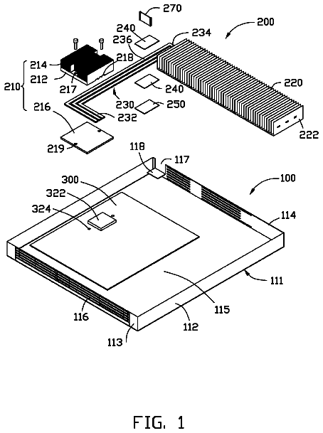
An optical drive includes a drive chassis and a front panel.
US 8,724,313 B2 · Assignee: Denso Corporation · Inventors: Nakasaka; Akira et al.
Sheet 1 of 26 from the published document. All sheets in the USPTO PDF
An electric power conversion apparatus is provided which includes electronic components, a cooler, an internal unit, a capacitor, and a case. The internal unit has a frame to which at least one of the electronic components and the cooler are secured and which surrounds all around the one of the electronic components. The frame includes unit fixing sections through which the internal unit is fixed to the case and capacitor fixing sections through which the capacitor is fixed to the internal unit. The capacitor fixing sections are located inward of the frame more than the unit fixing sections. The internal unit is fixed to the case and thus works as a beam to increase the mechanical rigidity of the case. The fixing of the internal unit to the case minimizes external force to be exerted through the case on the electronic component and the cooler.
1. Technical Field of the Invention The present invention relates generally to a power conversion apparatus in which electronic components constituting a power conversion circuit and a cooler for cooling at least some of the electronic components are disposed in a case.
1 of 26 drawing sheets so far from the published document, cropped to the drawing. Every sheet is in the USPTO PDF.
What the patent claimed, word for word. All of it is now free to use.
The present application claims benefits of priority of Japanese Patent Application No. 2010-244597 filed on Oct. 29, 2010 and Japanese Patent Application No. 2010-24557 filed on Feb. 5, 2010, the disclosures of which are incorporated herein by reference.
1. Technical Field of the Invention
The present invention relates generally to a power conversion apparatus in which electronic components constituting a power conversion circuit and a cooler for cooling at least some of the electronic components are disposed in a case.
An electric vehicle or a hybrid vehicle is equipped with a power conversion apparatus such as an inverter or a converter to convert source power into driving power for a drive motor.
As shown in FIG. 27, such a power conversion apparatus 9 includes various electronic components including semiconductor modules 921 each incorporating therein switching elements, and a capacitor 922. For example, refer to Japanese patent Application Laid-Open No. 2009-159767. To prevent the temperature of the semiconductor modules 921 from increasing excessively, a cooler 93 is disposed in contact with the semiconductor modules 921.
The power conversion apparatus 9 further includes a control circuit board 96 on which a control circuit for controlling the semiconductor modules 921 is formed. The electronic components including the semiconductor modules 921, the cooler 93 and the control circuit board 96 are fixed to a case 94, and sealingly enclosed within the case 94.
Accordingly, if the case 94 is not rigid enough, the electronic components and the control circuit board 96 fixed to the case 94 may vibrate considerably, causing wire breakage, or failure in the electronic components due to external force applied thereto.
When the power conversion apparatus 9 is located in an engine compartment of a vehicle, the case 94 may expand or contract considerably due to abrupt temperature change. In this case, since the components are fixed directly to the case 94, they may fail due to thermal stress applied to them.
The case 94 of the power conversion apparatus 9 is constituted of a case body 940, and bottom and top lids 941 and 942. Accordingly, the case 94 has two large sealing surfaces required to be water-tight. Accordingly, since the case 94 has to be provided with many sealing members, the power conversion apparatus 9 is disadvantageous in the manufacturing cost.
In addition, the maintainability of the power conversion apparatus 9 is not good enough in this case, because both the bottom lid 941 and the top lid 942 have to be removed for maintenance work. It might be possible that the case 94 has only one sealing surface, if the case 94 is constituted of a bottomed case body and a top lid. However, in this case, the maintainability and rigidity of the case 94 may become worse.
Further, since vibration of the electronic components directly fixed to the case 94 can transmit to a vehicle body through the case 94, unpleasant vibration sound may occur in the vehicle cabin. Conversely, since vibration of the engine can transmit to the electronic components and the control circuit board through the case 94, wire breakage or fault may occur.
The power conversion apparatus 9 has the electronic component such as the capacitor 922 affixed directly to the case 94, thus increasing difficult in assembling the power conversion apparatus 9 and resulting in an increase in production cost thereof.
It is therefore a principal object of the invention to avoid the disadvantages of the prior art.
It is another object of the invention to provide an improved structure of a power conversion apparatus which is equipped with a high-rigidity case and designed to minimize external force acting on electronic components, to be easy in assemble, to be excellent in maintenance, and to be produced at low costs.
According to one aspect of the invention, there is provided a power conversion apparatus which comprises: (a) electronic components constituting a power conversion circuit; (b) a cooler which works to cool at least a portion of the electronic components; (c) an internal unit having a frame to which the at least the portion of the electronic components and the cooler are secured and which surrounds all around the at least the portion of the electronic components; (d) a case in and to which the internal unit is disposed and fixed through the frame; and (e) a capacitor that is one of the electronic components and with which the internal unit is equipped. The frame includes unit fixing sections through which the internal unit is fixed to the case and capacitor fixing sections through which the capacitor is fixed to the internal unit. The capacitor fixing sections are located inward of the frame more than the unit fixing sections.
Specifically, at least one of the electronic components and the cooler are fixed to the frame. The at least one of the electronic component, the cooler, and the frame are assembled as the internal unit. The internal unit is secured to and disposed inside the case. The internal unit, therefore, works as a beam which increases the mechanical rigidity of the case without having to increase the thickness of the case itself and form a reinforcement rib on the case. This also permits material or production costs or weight of the case to be reduced.
The fixing of the internal unit to the case minimizes external force or pressure to be exerted through the case on the electronic component and the cooler in the internal unit, in other words, decreases vibrational or thermal effects on the electronic component and the cooler in the internal unit.
The assembling of the power conversion apparatus may be achieved by installing the electronic component on the frame to complete the internal unit and then putting the internal unit in the case, thus resulting in ease of producing the power conversion apparatus. The internal unit may be taken out of the case for maintenance thereof, thus resulting in improved maintenance workability. This also eliminates the need for the case to have a plurality of lids or doors, which permits a sealing surface between the case and a lid to be one in number. This improves the water tightness of the case, and reduces the sealing material of the case, to thereby reduce the material cost and man-hour cost for application of the sealing material to the case.
The internal unit is secured to the case through the frame. The frame, thus, works as a beam to enhance the mechanical rigidity of the case.
The frame is shaped to surround all around the electronic component, thereby shielding electromagnetic noise emitted from the electronic component. The case is sometimes made of a conductive material. The electromagnetic noise emitted from the electronic component is shielded doubly by the frame and the case.
The internal unit is equipped with the capacitor as one of the electronic components, thereby reducing external pressure to be exerted on the capacitor and mechanical vibration to be transmitted from the capacitor to the case. This minimizes transmission of undesirable noise arising from the vibration of the capacitor to, for example, inside a cabin of an automotive vehicle in which the power conversion apparatus is installed.
The frame includes unit fixing sections through which the internal unit is fixed to the case and capacitor fixing sections through which the capacitor is fixed to the internal unit. The capacitor fixing sections are located inward of the frame more than the unit fixing sections, thus permitting the unit fixing sections to be positioned outside the capacitor when the internal unit made by mounting the capacitor on the frame is secured to the case. This minimizes the possibility of physical interference of the capacitor with the case when the internal unit is mounted within the case.
The ends of the frame may be an antinode of vibration, so that the amplitude of vibration thereof will be great, while the center of the frame may be a node of vibration, so that the amplitude of vibration will be small. The amplitude of vibration of the capacitor fixing sections is, therefore, decreased by locating the capacitor fixing sections closer to the center of the frame than the unit fixing sections. This minimizes the transmission of vibration to the capacitor, thus resulting in a decreased possibility of malfunction of the capacitor.
In the preferred mode of the invention, the internal unit may have a plurality of semiconductor modules disposed inside the frame as ones of the electronic components. The semiconductor modules have switching elements installed therein. The semiconductor modes are each equipped with a main electrode terminal into or from which controlled electric power is inputted or outputted and which protrudes toward the capacitor. The capacitor fixing sections protrude from the frame toward the capacitor to have a top end located farther away from the frame than a top end of the main electrode terminal.
The above structure provides the power conversion apparatus which has enhanced heat and vibration resistances and is easy to assemble. Specifically, the main electrode terminals project toward the capacitor. If, therefore, top ends 971 of main electrode terminals 970, as illustrated in FIG. 28, are located farther from a frame 980 than top ends 961 of capacitor fixing sections 960, it will result in physical interference of the main electrode terminals 970 with a capacitor 922 unless protrusions 923 such as bosses are provided on the capacitor 922. The outer shell of the capacitor 922 is usually made of resin. The protrusions 923, thus, must be made of resin, so that it will susceptible to mechanical vibration or thermal stress. The top ends of the main electrode terminals of the semiconductor modules are, as described above, located closer to the frame than the top ends of the capacitor fixing sections, thus enabling the capacitor to be joined to the capacitor fixing sections without having to form any protrusions on the capacitor. The capacitor fixing sections may be made of metal like the frame and thus insusceptible to the vibration or thermal stress.
The internal unit incorporates therein a stacked body in which coolant passages and the semiconductor modules are stacked alternately. The frame includes a front wall section and a rear wall section which are located on sides of the frame in a stacking direction in which the coolant passages and the semiconductor modules are stacked and a pair of side wall sections joining the front and rear wall sections at ends thereof. This structure results in a decrease in external force or pressure to be exerted on the semiconductor modules with the switching elements susceptible to the external force, thereby improving the durability of the power conversion apparatus. The structure also permits the stacked body to be assembled outside the case, thus facilitating the ease of producing the power conversion apparatus. The stacked body is made of the coolant passages and the semiconductor modules which are stacked alternately, thus resulting in enhanced efficiency in cooling the semiconductor modules and also permitting the stacked body to be compact in size.
The frame includes the front wall section, the rear wall section, and the side wall sections joining the front and rear wall sections. The stacked body is retained by the front wall section, thus facilitating the retaining of the stacked body through the frame.
The internal unit is equipped with bus bars which have input/output terminals into or from which controlled electric power is input or outputted. The input/output terminals extend perpendicular to the side wall sections. The capacitor fixing sections are located in the stacking direction outward of two of side surfaces of the capacitor which extend in parallel to each other and perpendicular to the stacking direction. This permits the power conversion apparatus to be reduced in size. Specifically, the capacitor fixing sections are usually made of metal like the frame. The input/output terminals are usually subjected to high-voltage. It is, thus, necessary to place the capacitor fixing sections and the input/output terminals away from each other in order to ensure electric insulation therebetween. If capacitor fixing sections 957 are, as illustrated in FIG. 29, located inward of side surfaces 929a and 929b in the stacking direction X which are two of side surfaces 929 of a capacitor 922 and extend parallel to each other in the lateral direction Y, it will result in a decreased minimum distance d between input/output terminals 999 and the capacitor fixing sections 957. The distance d, therefore, has to be increased in order to ensure a required degree of the insulation between the input/output terminals 999 and the capacitor fixing sections 957, which will result in an increase in overall size of the power conversion apparatus. The power conversion apparatus of this invention, as described above, may be designed to have the capacitor fixing sections located outside the parallel extending side surfaces of the capacitor in the stacking direction, so that the capacitor fixing sections will be remote from the input/output terminals, thus eliminating the need for increasing the size of the frame and permitting the power conversion apparatus to be made compact in size.
The internal unit may be equipped with a pressure member which presses the stacked body in the stacking direction. The stacked body has a front end and a rear end which are opposite each other in the stacking direction. The pressure member is disposed between the rear end of the stacked body and the rear wall section. The front end of the stacked body is supported by the front wall section and has a coolant introduction tube through which coolant is introduced into the coolant passages and a coolant discharge tube from which the coolant is discharged from the coolant passages. The front wall section has formed therein recesses in which the coolant introduction tube and the coolant discharge tube are placed. The capacitor fixing sections protrude from the frame toward the capacitor and overlap at least partially with the recesses as viewed from a direction in which the capacitor fixing sections protrude. The reaction force of the pressure member is, therefore, absorbed by the frame. This eliminates the need for the case to have rigidity large enough to bear the reaction force of the pressure member or to include ribs, thus permitting the case to be light in weight and less expensive.
As viewed from the direction in which the capacitor fixing sections extend, the capacitor fixing sections at least partially overlap the recesses. This enhances the rigidity of the frame. Specifically, the formation of the recesses in the front wall section of the frame will result in a decrease in rigidity of the frame. The overlapping of the capacitor fixing sections with the recesses, however, compensates for such a lack of rigidity of the frame, thereby minimizing the deformation of the frame arising from exertion of physical pressure from the pressure member.
The frame, as described above, includes the plurality of unit fixing sections for fixing the internal unit to the case. At least one of the fixing sections may be located on the outside of each of two supports of the frame in the stacking direction where the frame is applied with the reaction force which is oriented outward in the stacking direction and exerted by the stacked body and the pressure member. This results in an increase in rigidity of the frame through the case against the reaction force exerted by the stacked body and the pressure member. In other words, the case serves to reinforce the frame, thereby avoiding the undesirable deformation of the frame arising from the reaction force.
The frame may have the front wall section and the rear wall section located at ends of the stacked body which are opposite to each other in the stacking direction and also have the side wall sections connecting the front wall section and the rear wall section together at ends of the side wall sections. This ensures the stability in retaining the stacked body inside the frame.
The wall thickness of the front wall section and the rear wall section are preferably larger than the wall thickness of the side wall section. This improves the rigidity of the front and rear wall sections subjected to the reaction force of the pressure member and also allows the side wall sections not subjected directly to the reaction force of the pressure member to be reduced in weight. This also permits the frame to be light in weight and ensures the frame to have rigidity large enough to resist the reaction force of the pressure member.
At least a portion of each of the front and rear wall sections may form an H-shaped wall section having a roughly H-shaped cross section. The H-shaped wall section is constituted of a pair of longitudinal plate sections perpendicular to the stacking direction and a connecting section connecting these longitudinal plate sections together. This permits the frame to be made light in weight and ensures the high rigidity of the front and rear wall sections.
At least a part of each of the side wall sections may form an L-shaped wall section having a roughly L-shaped cross section. The L-shaped wall section is constituted of a main wall having a major surface facing the inner surface of the frame and an inward portion projecting toward the inner side of the frame from one end of the main wall portion in the direction perpendicular to the stacking direction. This permits the side wall sections to be reduced in weight and their material cost to be decreased without sacrificing the rigidity thereof.
The cooler may includes cooling tubes each of which defines therein one of the coolant passages. Each of the cooling tubes has a length. The cooling tubes may be joined at ends opposite to each other in the lengthwise direction of the cooling tubes. The semiconductor modules may each have the main electrode terminal into or from which the controlled power is inputted or outputted and the control terminal into which controlled current to control operation of the switching elements. The main electrode terminal and the control terminal extend in opposite directions (i.e., height directions of the frame) which are perpendicular to the stacking direction and the longitudinal direction of the cooling tubes. The frame may be shaped to open both in the height directions, which facilitates the installation of bus bars or a control circuit board on the semiconductor modules.
The internal unit may include a control circuit board on which a control circuit for controlling the switching elements included in the semiconductor modules is formed. It is not necessary to secure the control circuit board directly to the case, thus facilitating the ease of installing the control circuit board in the internal unit and also minimizing the degree of external force acting on the control circuit board.
The frame may also include unit fixing sections through which the internal unit is secured to the case. The unit fixing sections are preferably located outside an outer edge of the control circuit board. This facilitates the ease of installing the internal unit in the case. Specifically, if the unit fixing sections are located inward of an outer edge of the control circuit board, the internal unit assembled with the control circuit board cannot be easily fixed to the case. In this case, to fix the internal unit to the case 4, it is necessary to drill holes penetrating the wall of the case through which bolts or the like are inserted in, for example. However, in this case, not only the workability is lowered, but also more sealing members have to be used to ensure the water tightness of the case. By locating the unit fixing sections outward of the outer edge of the control circuit board, such a problem will be alleviated.
The frame may be provided with board fixing sections for fixing the control circuit board to the internal unit, which are located more inward than the unit fixing sections. This facilitates the ease of installing the control circuit board on the frame and also placing the internal unit in the case.
The internal unit may include a terminal block on which input/output terminals for input and output of controlled electric power are mounted for making connection between the input/output terminals and external devices. This permits the terminal block to be installed in the internal unit outside the case, thus facilitating the ease of such installation.
The power conversion apparatus may be equipped with a plurality of bus bars which have the input/output terminals located at ends thereof. The power conversion apparatus may also include bus bar fixing sections for fixing the bus bars to the frame.
At least two of the bus bars may be partially molded with resin to form an integrated bus bar assembly. The frame may also include a plurality of bus bar fixing sections for fixing the bus bar assembly. At least two of the bus bar fixing sections are located closer to the terminal block than to the center of the frame. This ensures the stability in installing the bus bar assembly on the frame and also mounting the input/output terminals on the terminal block, thus assuring electric connections of the input/output terminals with external terminals.
The internal unit may be designed to have installed therein all the electronic components constituting the power conversion circuit, thereby protecting the electronic components from an external force and also facilitating the ease of manufacturing the power conversion apparatus and resulting in good maintainability of the electronic components.
The frame may also include a wire holding section through which a conductive wire is retained which has at least one of ends placed inside the case. The conductive wire may be so placed as to extend along the frame. This avoids the interference of the conductive wire with the internal unit when put in or taken out of the case.
The present invention will be understood more fully from the detailed description given hereinbelow and from the accompanying drawings of the preferred embodiments of the invention, which, however, should not be taken to limit the invention to the specific embodiments but are for the purpose of explanation and understanding only.
In the drawings:
FIG. 1 is a schematic explanatory sectional view of a power conversion apparatus according to the first embodiment of the invention;
FIG. 2 is a plan view of a frame of the power conversion apparatus of FIG. 1;
FIG. 3 is a bottom view of the frame shown in FIG. 2;
FIG. 4 is a cross-sectional view of FIG. 2 along the line A-A (or a-a);
FIG. 5 is a cross-sectional view of FIG. 2 along the line B-B;
FIG. 6 is a front view of a frame of the first embodiment;
FIG. 7 is a plan view of a frame of the first embodiment on which a stacked body, a terminal block and so forth are installed;
FIG. 8 is a plan view of the frame of the first embodiment on which a bus bar assembly is further installed;
FIG. 9 is a view of a frame as viewed from the direction of the arrow C of FIG. 8;
FIG. 10 is a cross-sectional view of FIG. 7 along the line D-D;
FIG. 11 is a plan view of a frame of the first embodiment on which a capacitor is further installed;
FIG. 12 is a view of the frame as viewed from a direction of the arrow E of FIG. 11;
FIG. 13 is a plan view of a frame of the first embodiment on which a control circuit board is further installed, that is, a plan view of an internal unit of the first embodiment;
FIG. 14 is a front view of an internal unit of the first embodiment;
FIG. 15 is a side view of an internal unit of the first embodiment;
FIG. 16 is a plan view of an internal unit housed in a case of the first embodiment;
FIG. 17 is a cross-sectional view of FIG. 16 along the line F-F;
FIG. 18 is a cross-sectional view of FIG. 16 along the line G-G;
FIG. 19 is a cross-sectional view of a power conversion apparatus according to the first embodiment as viewed along the line G-G of FIG. 16;
FIG. 20 is a cross-sectional view of a power conversion apparatus according to the second embodiment of the invention;
FIG. 21 is a plan view of a power conversion apparatus according to the second embodiment before a lid body is assembled;
FIG. 22 is a side view of an internal unit of a power conversion apparatus according to the second embodiment;
FIG. 23 is a bottom view of an internal unit of the second embodiment;
FIG. 24 is a front view of a frame of a power conversion apparatus according to the second embodiment;
FIG. 25 is a plan view of a frame of the second embodiment;
FIG. 26 is a bottom view of a frame of the second embodiment;
FIG. 27 is a cross sectional view of a conventional power conversion apparatus;
FIG. 28 is a side view of a comparative example of a power conversion apparatus; and
FIG. 29 is a plane view of a comparative example of a power conversion apparatus.
Referring to the drawings, wherein like reference numbers refer to like parts in several views, particularly to FIG. 1, there is shown an electric power conversion apparatus according to the first embodiment of the invention.
As shown in FIG. 1, the power conversion apparatus 1 of this embodiment is constituted of electronic components including semiconductor modules 21 and a capacitor 22, a cooler 3 for cooling at least some of the electronic components (the semiconductor modules 21 in this embodiment), and a case 4 housing the electronic components and the cooler 3. The semiconductor modules 21 and the cooler 3 are fixed to and integrated with a frame 5 to constitute an internal unit 10. The internal unit 10 is fixed to the case 4, and sealingly enclosed within the case 4.
As shown in FIGS. 16 to 18, the internal unit 10 is fixed to the case 4 through the frame 5. The frame 5 is made of conductive material, and formed in a shape to surround the semiconductor modules 21 constituting the internal unit 10 from all four sides. The frame 5 may be a shaped body of metal such as aluminum or steel, or alloy. The case 4 may also be a shaped body of metal such as aluminum or steel or alloy.
The internal unit 10 is, as illustrated in FIGS. 14 and 15, equipped with the capacitor 22 as one of the electronic components. The frame 5 has unit fixing sections 51 through which the internal unit 10 is secured to the case 4 and capacitor fixing sections 57 through which the capacitor 22 is retained by the internal unit 10. The capacitor fixing sections 57 are, as clearly illustrated in FIG. 3, located inward of the frame 5 than the unit fixing sections 51. In other words, the center of each of the capacitor fixing sections 57 lies within a quadrangle defined by line segments each of which extends between centers of adjacent two of the unit fixing sections 51.
Each of the semiconductor modules 21 incorporates therein switching elements such as IGBTs or MOSFETs. The semiconductor modules 21 are each constituted of a main body section 211 in which the switching elements are resin-molded, main electrode terminals 212 and control terminals 213. The main electrode terminals 212 and the control terminals 213 extend from the main body section 211 in the opposite directions. Controlled electric power is inputted to or outputted from each of the semiconductor modules 212 through the main electrode terminals 212. A control current to control the switching elements is inputted to each of the semiconductor modules 212 through the control terminals 213.
The cooler 3, as shown in FIGS. 7 and 10, includes cooling tubes 31 each having therein a coolant passage. The internal unit 10 incorporates therein a stacked body 11 in which the cooling tubes 31 and the semiconductor modules 21 are stacked alternately. Each of the semiconductor modules 21 is held between the cooling tubes 31 at both major surfaces thereof. Between each adjacent two of the cooling tubes 31, two semiconductor modules 21 are disposed.
The cooling tubes 31, as shown in FIG. 7, extend in their longitudinal direction (may be referred to as "the lateral direction Y") perpendicular to the stacking direction X. Each adjacent two of the cooling tubes 31 are joined through a deformable joint tube 32 at their both ends. The cooler 3 includes a coolant introduction tube 331 and a coolant discharge tube 332 which are joined to ends of one of the cooling tubes 31 which is located outermost of the stacked body 11 in the stacking direction X.
Accordingly, the coolant introduced from the coolant introduction tube 331 spreads in the longitudinal direction (lateral direction Y), while passing the joint tubes 32 to be distributed to the respective cooling tubes 31. The coolant exchanges heat with the semiconductor modules 21 while flowing through the respective cooling tubes 31. The coolant having a temperature increased by the heat exchange passes the joint tubes 32 on the downstream side, and is discharged from the coolant discharge tube 332.
As the coolant, there may be used a natural coolant such as water and ammonia, or water mixed with refrigerant such as ethylene glycol, or a fluorocarbon coolant such as fluorinert, or a chlorofluorocarbon coolant such as HCFC123 and HFC134a, or an alcoholic coolant such as methanol and alcohol, or a ketone coolant such as acetone.
The internal unit 10 includes a pressure member 12 for pressing the stacked body 11 in the stacking direction X. The pressure member 12 is interposed between an inner part of the frame 5 and one end of the stacked body 11 (this one end being referred to as "rear end" hereinafter) in the stacking direction X. The stacked body 11 is supported by another inner part of the frame 5 at the other end thereof (referred to as "front end" hereinafter).
The pressure member 12 is made by a leaf spring which bents convexly toward the stacked body 11. Between the pressure member 12 and the stacked body 11, a flat reinforcing plate 13 is interposed to prevent the pressing force of the pressure member 12 from being locally applied to the cooling tube 31 located at the rear end to thereby prevent this cooling tube 31 from being deformed. A support pin 14 is held between each of both ends of the pressure member 12 in the lateral direction Y and the frame 5. The pressure member 12 is supported by the pair of the support pins 14 at its rear side.
The frame 5 includes a front wall section 52 and a rear wall section 53 located on both sides of the stacked body 11 which are opposite each other in the stacking direction X, and a pair of side wall sections 54 joining the front and rear wall sections 52 and 53 at their both ends. Hence, as shown in FIGS. 2 and 3, the frame 5 has a substantially rectangular shape when viewed from the direction perpendicular to both the stacking direction X and the lateral direction Y (referred to as "height direction Z" hereinafter).
As show in FIGS. 1 to 3 and 19, the frame 5 includes unit fixing sections 51 for fixing the internal unit 10 to the case 4. At least one fixing section 54 is located on the outside of each of a pair of support sections (the inner surface 521 of the front wall section 52 and the inner surface 531 of the rear wall section 53) in the stacking direction X at which the frame 5 is applied with the reaction force toward the outside in the stacking direction X applied from the stacked body 11 and the pressure member 11. In this embodiment, two unit fixing sections 51 are located on the outside of the inner surface 521, and another two fixing sections 54 are located on the outside of the inner surface 531.
Each unit fixing section 51 is shaped to project outward from the frame 5 and is formed with a through hole. By inserting a bolt 511 into the through hole, and screwing the bolt 511 into a threaded hole formed in a corresponding one of unit support sections 41 formed inside the case 4 for each of the unit fixing sections 41, the frame 5 can be fixed to the case 4 to thereby fix the internal unit 10 to the case 4.
As shown in FIGS. 2, 4 and 5, the wall thicknesses t1 of the front wall section 52 and the rear wall section 53 are larger than the wall thickness t2 of the side wall section 54. Here, the wall thicknesses t1 and t2 are dimensions in the stacking direction X or lateral direction Y at portions to which the cooling tubes 30 are projected in the stacking direction X or lateral direction Y.
As shown in FIGS. 4 and 10, at least a part of each of the front wall section 52 and the rear wall section 53 forms an H-shaped wall section 55 having a roughly H-shaped cross section. The H-shaped wall section 55 is constituted of a pair of longitudinal plate sections 551 perpendicular to the stacking direction X, and a connecting section 552 connecting these longitudinal plate sections 551 together.
As shown in FIGS. 2 and 3, at least a part of each of the side wall sections 54 forms an L-shaped wall section having a roughly L-shaped cross section. As show in FIG. 5, the L-shaped wall section is constituted of a main wall portion 541 having a major surface facing the inner surface of the frame 5, and an inward portion 542 projecting toward the inner side of the frame 5 from one end of the main wall portion 541 in the direction perpendicular to the stacking direction X. In this embodiment, the L-shaped wall section is formed by the whole of the side wall section 54. As shown in FIGS. 2 and 7, the inward portion 542 of the side wall section 54 projects more inward in the vicinity of the support pin 14 than the other portion.
The frame 5 is open at both sides in the height direction Z. As shown in FIGS. 9 and 10, the main electrode terminals 212 and the control terminals 213 of each semiconductor module 21 respectively project to one side (top side) of the height direction Z and the other side (bottom side) of the height direction Z. In the present application, the description is made assuming that the bottom side of the height direction Z corresponds to the direction of projection of the main electrode terminals 212, and the top side of the height direction Z corresponds to the direction of projection of the control terminals 213. However, this assumption is just for explanation. Likewise, the words "front", "rear", "lateral" are also just for explanation.
As shown in FIGS. 1 and 13 to 19, the internal unit 10 includes a control circuit board 6 on which a control circuit for controlling the switching elements included in the semiconductor modules 21 is formed. The control terminals 213 of the semiconductor module 21 are connected to the control circuit board 6. As shown in FIGS. 13 and 14, the unit fixing sections 51 of the frame 5 are located more outward than the outer edge of the control circuit board 6.
The frame 5 is, as shown in FIGS. 2, 14 and 15, provided with four board fixing sections 56 for fixing the control circuit board 6 to the internal unit 10, which are located more inward than the unit fixing sections 51. The board fixing sections 56 are constituted of two bosses formed in each of the front wall section 52 and the rear wall section 53 so as to project upward in the height direction Z. As shown in FIGS. 13 to 15, each of the board fixing sections 56 is formed with a threaded hole in which a screw 561 is inserted to secure the control circuit board 56 to the frame 5 in four positions.
The capacitor fixing sections 57 are constituted of two bosses formed in each of the front wall section 52 and the rear wall section 53 so as to project to the opposite side of the board fixing sections 56, that is, downward in the height direction Z. Each of the capacitor fixing sections 57 is formed with a threaded hole in which a bolt 571 is inserted to secure the capacitor 22 to the frame 5 in four positions.
The main conductor terminals 212 of the semiconductor modules 21, as illustrated in FIG. 12, protrude toward the capacitor 22. The capacitor fixing sections 57 protrude from the frame 5 toward the capacitor 22. The capacitor fixing sections 57 have top ends 570 located farther from the frame 5 than the top ends 210 of the main electrode terminals 212.
As shown in FIGS. 11 to 15, the internal unit 10 includes a terminal block 7 on which input/output terminals 71 for input and output of controlled electric power are mounted for making connection between the input/output terminals 71 and external devices such as a DC battery and a three-phase electric rotating machine. The terminal block 7 is fixed to two support arms 543 by bolts 544, the support arms 543 being formed in one of the side wall sections 54 so as to project outward.
The input/output terminals 71 include a pair of capacitor terminals 71P and 71N electrically connected to a pair of electrodes of the capacitor 22, and three output terminals 71U, 71V and 71W electrically connected to the main electrode terminals 212 of the semiconductor modules 21 and to be respectively connected to the U-phase, V-phase and W-phase electrodes of the three-phase electric rotating machine. The input/output terminals 71 are respectively formed at one ends of bus bars which are connected to the capacitor 22 or semiconductor modules 21 at the other ends thereof.
Of these bus bars, the ones 70 respectively formed with the output terminals 71U, 71V and 71W are partially molded with resin to form an integrated bus bar assembly 72. As shown in FIGS. 3, 14 and 15, the frame 5 includes bus bar fixing sections 58 for fixing the bus bar assembly 72. In this embodiment, the bus bar fixing sections 58 are formed in three positions. Two of the three bus bar fixing sections 58 are located at positions closer to the terminal block 7 than to the center of the frame 5.
The input terminals 71 of the bus bars 70, as illustrated in FIG. 11, extend perpendicular to the side wall sections 54 of the frame 5 (i.e., the lateral direction Y). The capacitor fixing sections 57 are located outward of side surfaces 29a and 29b of the capacitor 22 in the stacking direction X. The side surfaces 29a and 29b are two of four side surfaces 29 of the capacitor 22 which extend parallel to each other in the lateral direction Y.
The pressure member 12 is, as can be seen in FIG. 7, disposed between the rear end of the stacked body 11 and the rear wall section 53 of the frame 5. The front end of the stacked body 11 is retained by the front wall section 52 of the frame 5. The coolant introduction tube 331 and the coolant discharge tube 332 are joined to the front end of the stacked body 11 to feed and discharge the coolant to and from the cooling tubes 31, respectively. The front wall section 52 has, as clearly illustrated in FIGS. 2 and 3, recesses or concave portions 522 in which the coolant introduction tube 331 and the coolant discharge tube 332 are placed. The capacitor fixing sections 57, as illustrated in FIG. 12, extend from the frame 5 toward the capacitor 22. As viewed from a direction in which the capacitor fixing sections 57 extend, the capacitor fixing sections 57, as illustrated in FIG. 3, at least partially overlap the concave portions 522.
The internal unit 10 includes all the electronic components constituting the power conversion circuit. That is, all the electronic components of the power conversion apparatus 1 belong to the internal unit 10, and none of the electronic components is directly fixed to the case 4. As shown in FIG. 1, the case 4 is constituted of a case body 40 which is open upward, and a lid body 400 closing the opening of the case body 40. The unit support sections 41 are formed integrally with the case body 40.
The description continues in the full USPTO document.
About 6,862 words. The USPTO PDF has it with every drawing.
Fees are due 3.5, 7.5 and 11.5 years after grant. This patent expired on May 13, 2026, so the fee marked "not paid" was the one that went unpaid.
POWER CONVERSION APPARATUS
Filed Feb 2011 · published Aug 2011Power conversion apparatus
Filed Feb 2011 · granted May 2014Earlier publications, parents and continuations. None of them can still be enforced, or this patent would not be listed.
Prior art cited by the examiner or applicant. Useful when you check your own idea for novelty.
Everything on this page comes from the documents linked above.