 Lapsed, fee not paid12 drawings
Energy & Sustainability · US 8,723,485 B2
Power supply system
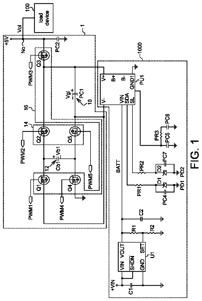
A power supply system includes an output node, an internal power supply unit, a boost storage unit, a charging path unit, and a discharging path unit.
US 8,723,496 B2 · Assignee: Southeast University · Inventors: Sun; Weifeng et al.
Sheet 1 of 12 from the published document. All sheets in the USPTO PDF
A switching power supply with a quick transient response is provided. A hysteretic control loop which comprises a hysteretic controller (117) and a control signal gate (116) is added to the original PWM control loop of the switching power supply. The hysteretic controller (117) is used to detect an output voltage (Vout) of the switching power supply and compare the output voltage (Vout) of the switching power supply with a reference voltage (Vref). When a load current (Iout) of the switching power supply is suddenly changed, the output voltage (Vout) of the switching power supply fluctuates. If the output voltage (Vout) of the switching power supply is in a setting range of the hysteretic voltage, output terminals (SELp, SELn) of the hysteretic controller (117) are in a low potential, and the control signal gate (116) selects output signals (Qp1, Qn1) from a PWM controller (101) as input signals of a gate signal drive circuit (106). If the fluctuation of the output voltage (Vout) of the switching power supply exceeds the setting range of the hysteretic voltage, an output terminal (SELp, SELn) of the hysteretic controller (117) outputs a high potential, and the control signal gate (116) selects output signals (Qp2, Qn2) of the hysteretic controller (117) as input signals of the gate signal drive circuit (106), so the operation of switching tubes (111, 112) at the power lever (102) of the switching power supply is controlled to stabilize the output voltage (Vout).
1.
8 of 12 drawing sheets so far from the published document, cropped to the drawing. Every sheet is in the USPTO PDF.
What the patent claimed, word for word. All of it is now free to use.
This application is a National Phase Patent Application and claims priority to and benefit of International Application Number PCT/CN2010/078069, filed on Oct. 25, 2010, which claims priority to and benefit of Chinese Patent Application Number 201010248402.5, filed on Aug. 6, 2010, the entire disclosure of which are incorporated herein by reference.
1.
The present invention relates to a switching power supply with quick transient response against abrupt changes of load current, in particular to a switching power supply with variable output voltage and quick transient response, which is helpful for improving transient response rate of switching power supply, reducing fluctuation amplitude of output voltage, and reducing the time required for stabilizing the output voltage.
Nowadays, as microprocessors and DSPs (Digital Signal Processors) develop, there is a demand for switching power supply with high current variation rate and quick transient response. In fact, microprocessors and DSPs are rapid-changing loads for switching power supply. For instance, to reduce power consumption, in idle state, microprocessors and DSPs enter into "Sleep Mode", in which the working current is very low; once needed, microprocessors and DSPs create instantaneous high current; thus, the switching power supply must have capability of quick transient response.
LnLC (Linear non-linear Control) is a method for improving the transient response rate for switching power supply, by adding a non-linear control loop on the basis of the existing linear control loop. When the load current is stable, the linear control loop of the switching power supply functions; once the load current changes abruptly and results in an output voltage variation beyond the limit, the non-linear control loop takes the place of the linear control loop and increases the transient response rate. Such a non-linear control loop requires two comparators to detect whether the output voltage is lower than the lower limit or higher than the upper limit. For a switching power supply unit with variable output voltage, additional circuits are required to produce limit which changes by following the output voltage, as a result of which, the circuit complexity and chip area are increased. A satisfactory transient response improving circuit must be capable of quickly stabilizing the output voltage, and preferably has simple structure and are less influenced by manufacturing technique and working environment.
The present invention provides a switching power supply with quick transient response, which is helpful for improving the output voltage fluctuation amplitude and stabilization time of switching power supply.
The present invention employs the following technical scheme:
A switching power supply with quick transient response, comprising: a power stage with inductor, a PWM controller, and a grid signal drive circuit, wherein, a D/A (digital-to-analog) converter designed to produce a reference voltage is connected to a reference voltage input terminal of the PWM controller, an oscillator designed to produce clock signals is connected to a clock signal input terminal of the PWM controller, the output terminal of the power stage is connected to a voltage feedback signal input terminal of the PWM controller, which utilizes the output voltage of the switching power supply as the feedback signal, the PWM controller is designed to collect current signals of inductor in the power stage and take the collected current signal as the input signal for the current feedback signal input terminal of the PWM controller, an output terminal of the grid signal drive circuit is connected to an input terminal of the power stage, the other output terminal of the grid signal drive circuit is connected to the other input terminal of the power stage, and the output terminal of the power stage is used as the output terminal of the switching power supply; wherein, the switching power supply further includes a delay controller and a control signal gate, wherein, an output terminal of the control signal gate is connected to an input terminal of the grid signal drive circuit, the other output terminal of the control signal gate is connected to the other input terminal of the grid signal drive circuit, the reference voltage input terminal of the delay controller is connected to the reference voltage output terminal of the D/A converter, the clock signal input terminal of the delay controller is connected to the clock signal output terminal of the oscillator, the delay controller takes the output voltage from the switching power supply as its input voltage and input it into the voltage signal input terminal of the delay controller, the delay controller is designed to detect the output voltage of the switching power supply and compare the output voltage with the reference voltage; if the output voltage from the switching power supply is within the preset delay voltage range, the output terminal SEL.sub.p and output terminal SEL.sub.n of the delay controller will be both in low potential, and the control signal gate select the output signal Q.sub.p1 and output signal Q.sub.n1 from the PWM controller as the input signals for the grid signal drive circuit, the delay voltage range is the reference voltage.+-.(10.about.30 mV); if the output voltage fluctuation amplitude of the switching power supply goes beyond the preset delay voltage range, the output terminal SEL.sub.p or output terminal SEL.sub.n of the delay controller will output high potential, and the control signal gate will select the output signal Q.sub.p2 and output signal Q.sub.n2 from the delay controller as the input signals for the grid signal drive circuit.
Advantages and Notable Effects of the Invention
The present invention improves the transient response capability of switching power supply by adding an additional delay controller on the existing PWM controller of the switching power supply. When the load current of the switching power supply changes abruptly and the output voltage fluctuates and goes beyond the delay voltage range, the delay controller will take the place of the PWM controller and functions.
If the output voltage is too high, the delay controller will switch off the P-MOS tube (P type power MOS tube) and switch on the N-MOS tube (N type MOS tube), so that the output filter capacitor discharges and thereby the output voltage is decreased. After the delay control loop operates for one or two PWM oscillation cycles, the switching power supply will automatically switch to be controlled by the PWM controller, while the delay controller still detects whether the output voltage is within the delay voltage range; if the output voltage goes beyond the delay voltage range again, the switching power supply will switch to be controlled by the delay controller again, till the output voltage is stabilized.
If the output voltage is too low, the delay controller will switch on the P-MOS tube and switch off the N-MOS tube, so that the output filter capacitor is charged, and thereby the output voltage is increased. After the delay controller operates for one or two PWM oscillation cycles, the switching power supply will automatically switch to be controlled by the PWM controller, while the delay controller still detects whether the output voltage is within the delay voltage range; if the output voltage goes beyond the delay voltage range again, the switching power supply will switch to be controlled by the delay controller again, till the output voltage is stabilized.
The new added delay controller only operates when the output voltage fluctuation amplitude goes beyond the delay voltage range, and therefore has no influence on other features of the switching power supply. In addition, the output voltage of the switching power supply provided in the present invention is variable, and the transient response rate against load current fluctuations can be effectively improved at different output voltage.
FIG. 1 is a circuit block diagram of a switching power supply with variable output voltage, which includes a power stage, a PWM controller, and a grid signal drive circuit.
FIG. 2 is a detailed circuit block diagram of a grid signal drive circuit, which includes logic gate circuits and inverter drive chain circuits.
FIG. 3 is a circuit block diagram of a switching power supply with variable output voltage provided in the present invention, including a delay controller, a control signal gate, a power stage, a PWM controller, and a grid signal drive circuit.
FIG. 4 is a detailed circuit block diagram provided in the present invention, including a delay comparator, edge detection circuits, a timer circuit, logic gate circuits, and a control signal gate.
FIG. 5 is a circuit diagram of the delay comparator, which has variable center comparison voltage and determined delay voltage range.
FIG. 6 shows an edge detection circuit, which is designed to detect jumps in the output of the delay comparator.
FIG. 7 shows the timer circuit, which is designed to control the operating time of the delay control loop.
FIG. 8 shows the control signal gate, which is designed to select the control signal from the PWM controller or the control signal from the delay controller, and input the selected signal into the grid signal drive circuit, so as to decide the grid signal of the power MOS tube.
FIG. 9 shows the signal transmission oscillogram of the grid signal drive circuit.
FIG. 10 shows the signal transmission oscillogram in the delay controller after output voltage fluctuation.
FIG. 11 shows the output voltage fluctuation and the grid signal oscillogram of the delay controller after an abrupt change of load current.
FIG. 12 shows the transient response of an existing switching power supply against abrupt changes of load current.
FIG. 13 shows the transient response of a switching power supply with a delay controller against abrupt changes of load current.
A switching power supply with quick transient response, comprising: a power stage 102 with an inductor 113, a PWM controller 101, and a grid signal drive circuit 106, wherein, a D/A converter 110 designed to produce a reference voltage is connected to a reference voltage input terminal of the PWM controller 101, an oscillator 109 designed to produce clock signals is connected to a clock signal input terminal of the PWM controller 101, the output terminal of the power stage 102 is connected to a voltage feedback signal input terminal of the PWM controller 101 which utilizes the output voltage from the switching power supply as the feedback signal, the PWM controller 101 is designed to collect the current signal of the inductor 113 in the power stage 102 and take the collected current signal as the input signal for the current feedback signal input terminal of the PWM controller 101, an output terminal of the grid signal drive circuit 106 is connected to an input terminal of the power stage 102, the other output terminal of the grid signal drive circuit 106 is connected to the other input terminal of the power stage 102, and the output terminal of the power stage 102 is used as the output terminal of the switching power supply; wherein, the switching power supply further includes a delay controller 117 and a control signal gate 116, wherein, an output terminal of the control signal gate 116 is connected to an input terminal of the grid signal drive circuit 106, the other output terminal of the control signal gate 116 is connected to the other input terminal of the grid signal drive circuit 106, the reference voltage input terminal of the delay controller 117 is connected to the reference voltage output terminal of the D/A converter 110, the clock signal input terminal of the delay controller 117 is connected to the clock signal output terminal of the oscillator 109, the delay controller 117 takes the output voltage from the switching power supply as its input voltage and input into the voltage signal input terminal of the delay controller 117, the delay controller 117 is designed to detect the output voltage value of the switching power supply and compare it with the reference voltage; if the output voltage from the switching power supply is within a preset delay voltage range, the output terminal SEL.sub.p and output terminal SEL.sub.n of the delay controller 117 will be both in low potential, and the control signal gate 116 will select the output signal Q.sub.p1 and output signal Q.sub.n1 from the PWM controller 101 as the input signals for the grid signal drive circuit 106, the delay voltage range is the reference voltage.+-.(10.about.30 mV); if the output voltage fluctuation amplitude of the switching power supply goes beyond the preset delay voltage range, the output terminal SEL.sub.p or output terminal SEL.sub.n of the delay controller 117 will output high potential, and the control signal gate 116 will select the output signal Q.sub.p2 and output signal Q.sub.n2 from the delay controller as the input signals for the grid signal drive circuit 106.
The delay controller 117 comprises a delay comparator 401, a first inverter 402, a timer circuit 403, a rising edge detection circuit 408, and a falling edge detection circuit 409, wherein, the output terminal of the switching power supply is connected to the negative phase input terminal of the delay comparator 401, the output terminal of the D/A converter (DAC) 110 is connected to the positive phase input terminal of the delay comparator 401, the output terminal of the delay comparator 401 is connected to the input terminal of the first inverter 402, an input terminal of the rising edge detection circuit 408, and an input terminal of the falling edge detection circuit 409 respectively, and is used as the output terminal Q.sub.p2 of the delay controller 117, the output terminal of the first inverter 402 is used as the output terminal Q.sub.n2 of the delay controller 117, the other two input terminals of the rising edge detection circuit 408 are connected to the output terminal Reset and enable terminal EN of the timer circuit 403, an output terminal Pulse.sub.p of the rising edge detection circuit 408 is connected to an input terminal of the timer circuit 403, the other output terminal of the rising edge detection circuit 408 is used as the output terminal SEL.sub.p of the delay controller 117, the other two input terminals of the falling edge detection circuit 409 are connected to the output terminal Reset and enable terminal EN of the timer circuit 403 respectively, the output terminal Pulse of the falling edge detection circuit 409 is connected to the other input terminal of the timer circuit 403, and the other output terminal of the falling edge detection circuit 409 is used as the output terminal SEL.sub.n of the delay controller 117, the clock signal input terminal and enable signal input terminal of the timer circuit 403 are used as the clock signal input terminal and enable signal input terminal of the delay controller 117 respectively.
The control signal gate 116 comprises a first gate 801, a second gate 802, a third gate 803, a fourth gate 804, a first NOR gate 805, a second NOR gate 807, a second inverter 806, and a third inverter 808. The output terminal SE.sub.n of the delay controller 117 is connected to an input terminal SEL of the third gate 803 and an input terminal SEL of the fourth gate 804 respectively, the other output terminal SEL.sub.p of the delay controller 117 is connected to an input terminal SEL of the first gate 801 and an input terminal SEL of the second gate 802 respectively, the output terminal Q.sub.p1 of the PWM controller 101 is connected to the other input terminal IN1 of the second gate 802 and the other input terminal IN1 of the fourth gate 804 respectively, the other output terminal Q.sub.n1 of the PWM controller 101 is connected to the other input terminal IN1 of the first gate 801 and the other input terminal IN1 of the third gate 803 respectively, the other output terminal Q.sub.p2 of the delay controller 117 is connected to the other input terminal IN2 of the second gate 802 and the other input terminal IN2 of the fourth gate 804 respectively, the other output terminal Q.sub.p2 of the delay controller 117 is connected to the other input terminal IN2 of the first gate 801 and the other input terminal IN2 of the third gate 803 respectively. The output terminals of the first gate 801 and third gate 803 are connected to the two input terminals of the first NOR gate 805, the output terminal of the first NOR gate 805 is connected to the input terminal of the second inverter 806, the output terminal of the second inverter 806 is used as the output terminal Q.sub.n of the control signal gate 116, the output terminals of the second gate 802 and fourth gate 804 are connected to the two input terminals of the second NOR gate 807, the output terminal of the second NOR gate 807 is connected to the input terminal of the third inverter 808, and the output terminal of the third inverter 808 is used as the output terminal Q.sub.p of the control signal gate 116.
The delay comparator 401 comprises an operation amplifier 501, a comparator 502, and a first resistor 503, a second resistor 504, a third resistor 505, and a fourth resistor 506. The output terminal V.sub.ref of the D/A converter (DAC) 110 is connected to one end of the first resistor 503 and one end of the third resistor 505 respectively, the other end of first resistor 503 is connected to one end of the second resistor 504 and the positive phase input terminal of the operation amplifier 501, the other end of the second resistor 504 is connected to the output terminal of the comparator 502 and is used as the output terminal Q.sub.p2 of the delay comparator, the other terminal of the third resistor 505 is connected to one end of the fourth resistor 506 and the negative phase input terminal of the operation amplifier 501, the other end of the fourth resistor 506 is connected to the output terminal of the operation amplifier 501 and the positive phase input terminal of the comparator 502, and the negative phase input terminal of the comparator 502 is connected to the output terminal V.sub.out of the switching power supply.
Said rising edge detection circuit 408 comprises a first inverter delay chain 601, a fourth inverter 602, a fifth inverter 612, a sixth inverter 614, a first NAND gate 603, a second NAND gate 611, a third NAND gate 613, a first D flip-flop 605, and a first power input 604. The output terminal Q.sub.p2 of the delay comparator 401 is connected to the input terminal of the first inverter delay chain 601, an input terminal of the first NAND gate 603 and an input terminal of the third NAND gate 613 respectively, the output terminal of the first inverter delay chain 601 is connected to the input terminal of the fourth inverter 602, the output terminal of the fourth inverter 602 is connected to the other input terminal of the first NAND gate 603, the output terminal of the first NAND gate 603 is connected to the clock input terminal of the first D flip-flop 605 and is used as the output terminal Pulse.sub.p of the rising edge detection circuit 408; the output terminal Reset and enable terminal EN of the timer circuit 403 are connected to the two input terminals of the second NAND gate 611 respectively, the output terminal of the second NAND gate 611 is connected to the input terminal of the fifth inverter 612, the output terminal of the fifth inverter 612 is connected to the other input terminal of the third NAND gate 613, the output terminal of the third NAND gate 613 is connected to the input terminal of the sixth inverter 614, the output terminal of the sixth inverter 614 is connected to the enable input terminal of the first D flip-flop 605, the data input terminal of the first D flip-flop 605 is connected to the first power input 604, and the output terminal of the first D flip-flop 605 is used as the output terminal SEL.sub.p of the rising edge detection circuit 408.
Said falling edge detection circuit 409 comprises a second inverter delay chain 606, a seventh inverter 607, an eighth inverter 609, a third NOR gate 608, a fourth NOR gate 616, a fourth NAND gate 615, and a second D flip-flop 610. The output terminal Q.sub.p2 of the delay comparator 401 is connected to the input terminal of the second inverter delay chain 606, an input terminal of the third NOR gate 608 and an input terminal of the fourth NOR gate 616 respectively, the output terminal of the second inverter delay chain 606 is connected to the input terminal of the seventh inverter 607, the output terminal of the seventh inverter 607 is connected to the other input terminal of the third NOR gate 608, the output terminal of the third NOR gate 608 is connected to the input terminal of the eighth inverter 609, the output terminal of the eighth inverter 609 is connected to the clock input terminal of the D flip-flop 610 and is used as the output terminal Pulse.sub.n of the falling edge detection circuit 409; the output terminal Reset and enable terminal EN of the timer circuit 403 are connected to the two input terminals of the fourth NAND gate 615 respectively, the output terminal of the fourth NAND gate 615 is connected to the other input terminal of the fourth NOR gate 616, the output terminal of the fourth NOR gate 616 is connected to the enable input terminal of the second D flip-flop 610, the data input terminal of the second D flip-flop 610 is connected to the first power input 604, and the output terminal of the second D flip-flop 610 is used as the output terminal SEL.sub.n of the falling edge detection circuit 409.
Said timer circuit 403 comprises a ninth inverter 701, a tenth inverter 709, an eleventh inverter 710, a fifth NAND gate 703, a fifth NOR gate 702, a third D flip-flop 705, a fourth D flip-flop 706, a fifth D flip-flop 707, a third inverter delay chain 708, and a second power input 704. The output terminal Pulse.sub.p of the rising edge detection circuit 408 and the output terminal Pulse.sub.n of the falling edge detection circuit 409 are connected to the two input terminals of the fifth NAND gate 703, the output terminal of the fifth NAND gate 703 is connected to the input terminal of the tenth inverter 709, and the output terminal of the tenth inverter 709 is connected to the clock input terminal of the third D flip-flop 705. The enable terminal EN is connected to the input terminal of the ninth inverter 701, the output terminal of the ninth inverter 701 is connected to an input terminal of the fifth NOR gate 702, the other input terminal of the fifth NOR gate 702 is connected to the output terminal of the third inverter delay chain 708, the output terminal of the fifth NOR gate 702 is connected to the enable input terminal of the third D flip-flop 705, the data input terminal of the third D flip-flop 705 is connected to the second power input 704, the output terminal of the third D flip-flop 705 is connected to the enable input terminals of the fourth D flip-flop 706 and fifth D flip-flop 707, the clock input terminal of the fourth D flip-flop 706 is connected to the output terminal CLK of the oscillator 109, the data input terminal of the fourth D flip-flop 706 is connected to the antiphase output terminal of the fourth D flip-flop 706 and the clock input terminal of the fifth D flip-flop 707 respectively, the data input terminal of the fifth D flip-flop 707 is connected to the antiphase output terminal of the fifth D flip-flop 707, the positive phase output terminal of the fifth D flip-flop 707 is connected to the input terminal of the eleventh inverter 710 and the input terminal of the third inverter delay chain 708 respectively, and the output terminal of the eleventh inverter 710 is used as the output terminal Reset of the timer circuit 403.
Said PWM controller 101 comprises an error amplifier 103, a PWM comparator 104, a RS flip-flop 105, a current detection circuit 107, and a ramp current compensation circuit 108. The positive phase input terminal of the error amplifier 103 is used as the reference voltage input terminal of the PWM controller 101, the negative phase input terminal of the error amplifier 103 is used as the voltage feedback signal input terminal of the PWM controller 101, the output terminal V.sub.e of the error amplifier 103 is connected to the positive phase input terminal of the PWM comparator 104, the input terminal of the current detection circuit 107 is used as the current feedback signal input terminal of the PWM controller 101, the output terminal of the current detection circuit 107 is connected to the input terminal of the ramp current compensation circuit 108, the output terminal V.sub.sense of the ramp current compensation circuit 108 is connected to the negative phase input terminal of the PWM comparator 104, the output terminal PO of the PWM comparator 104 is connected to the reset input terminal R of the RS flip-flop 105, the set input terminal S of the RS flip-flop 105 is used as the clock input terminal of the PWM controller 101, the positive phase output terminal and negative phase output terminal of the RS flip-flop 105 are used as the output terminal Q.sub.p1 and Q.sub.n1 of the PWM controller 101 respectively.
Said power stage 102 comprises a P-MOS tube 111, an N-MOS tube 112, a filter inductor 113, a filter capacitor 114, a load resistor 115, and a third power input 116. The grid of the P-MOS tube 111 is used as an input terminal G.sub.p of the power stage 102, the grid of the N-MOS tube 112 is used as the other input terminal G.sub.n of the power stage 102, the source electrode of the P-MOS tube 111 is connected to the third power input 116, the drain electrode of the P-MOS tube 111 is connected to the drain electrode of the N-MOS tube 112 and one end of the filter inductor 113 respectively and is used as an inductive current feedback output terminal of the power stage 102, and the source electrode of the N-MOS tube 112 is connected to ground potential; the other end of the filter inductor 113 is connected to one end of the filter capacitor 114 and one end of the load resistor 115 respectively and is used as an output voltage feedback output terminal of switching power supply of the power stage 102, the other end of the filter capacitor 114 and the other end of the load resistor 115 are connected to ground potential.
The grid signal drive circuit 106 comprises a sixth NOR gate 301, a seventh NOR gate 307, a sixth NAND gate 302, a seventh NAND gate 308, a twelfth inverter 303, a thirteenth inverter 304, a fourteenth inverter 306, a fifteenth inverter 309, a first inverter drive chain 305, and a second inverter drive chain 310. An input terminal of the sixth NAND gate 302 is used as an input terminal of the grid signal drive circuit 106, the other input terminal of the sixth NAND gate 302 is connected to the output terminal of the sixth NOR gate 301, the output terminal of the sixth NAND gate 302 is connected to the input terminal of the twelfth inverter 303, the output terminal of the twelfth inverter 303 is connected to the input terminal of the thirteenth inverter 304 and an input terminal of the seventh NOR gate 307 respectively, the output terminal of the thirteenth inverter 304 is connected to the input terminal of the first inverter drive chain 305, the output terminal of the first inverter drive chain 305 is connected to the input terminal of the fourteenth inverter 306 and is used as the output terminal G.sub.p of the grid signal drive circuit 106, the output terminal of the fourteenth inverter 306 is connected to the other input terminal of the seventh NOR gate 307, the output terminal of the seventh NOR gate 307 is connected to an input terminal of the seventh NAND gate 308, the other input terminal of the seventh NAND gate 308 is used as the other input terminal of the grid signal drive circuit 106, the output terminal of the seventh NAND gate 308 is connected to the input terminal of the fifteenth inverter 309, the output terminal of the fifteenth inverter 309 is connected to the input terminal of the second inverter drive chain 310 and an input terminal of the sixth NOR gate 301 respectively, the output terminal of the second inverter drive chain 310 is connected to the other input terminal of the sixth NOR gate 301 and is used as the output terminal G.sub.n of the grid signal drive circuit 106.
Hereunder the embodiments of the present invention will be further detailed, with reference to the accompanying drawings:
As shown in FIG. 1, the PWM controller 101, grid signal drive circuit 106, power stage 102, oscillator 109, and DAC (D/A Converter) 110 form a step-down switching power supply, wherein, the PWM controller 101 comprises an error amplifier 103, a PWM comparator 104, a RS flip-flop 105, a current detection circuit 107, and a ramp current compensation circuit 108. The oscillator 109 provides clock signals for the PWM controller 101, the DAC 110 provides a reference voltage for the PWM controller, and DAC 110 produces variable reference voltage to regulate the output voltage of the switching power supply. The power stage 102 comprises a P-MOS tube 111, an N-MOS tube 112, a filter inductor 113, a filter capacitor 114, and a load resistor 115.
When the load current is constant, the output voltage of the switching power supply is stable, and the switching power supply operates in PWM mode. At the beginning of each operating cycle, the oscillator 109 is at low electrical level, so that the RS flip-flop 105 is set, output Q.sub.p1=1 and Q.sub.n1=0; Q.sub.p1 and Q.sub.n1 are input to the grid signal drive circuit 106, and grid signals G.sub.p=0 and G.sub.n=0 are produced, and thereby the P-MOS tube 111 is switched on and the N-MOS tube 112 is switched off; therefore, the current in the filter inductor 113 increases. The output voltage V.sub.out is fed back to the negative phase input terminal of the error amplifier 103, and therefore the difference between the output voltage V.sub.out and the output reference voltage V.sub.ref produced by the DAC 110 is amplified by the error amplifier 103, to obtain a control voltage V.sub.e. At the same time, the current detection circuit 107 detects the current flow through the P-MOS tube 111; to suppress sub-harmonic oscillation, the ramp current compensation circuit 108 compensates the detected current to obtain a voltage V.sub.sense. As the current in the P-MOS tube 111 increases, the voltage V.sub.sense increases; when the voltage V.sub.sense exceeds the control voltage V.sub.e, the PWM comparator will output a low potential to reset the RS flip-flop 105, the outputs are Q.sub.p1=0 and Q.sub.n1=1; Q.sub.p1 and Q.sub.n1 are input to the grid signal drive circuit 106, and grid signals G.sub.p=1 and G.sub.n=1 are produced consequently, and thereby the P-MOS tube 111 is switched off, while the N-MOS tube 112 is switched on, so that the current in the filter inductor 113 decreases; at the beginning of the next operating cycle, above operating process will be repeated.
FIG. 2 shows the grid signal drive circuit 106. Since the power MOS tube has very large size, the parasitic grid capacitance is big. To switch on or off the power MOS tubes quickly, a grid signal drive circuit 106 is required. In addition, the grid signal drive circuit 106 can also prevent the P-MOS tube 111 and N-MOS tube 112 from being switched on at the same time, and thereby prevent instantaneous high current that may result in reduced efficiency or destruction of power tubes. Two input NOR gates 301 and 307 are utilized as enable circuits of grid signal for the MOS tubes. As shown in FIG. 9, in PWM mode, before an operating cycle ends, Q.sub.p1=0, Q.sub.n1=1, and G.sub.p=1, G.sub.n=0, and the P-MOS tube is switched off, while the N-MOS tube is switched on; at the beginning of the next operating cycle, the oscillator 109 sets the RS flip-flop 105, so that Q.sub.p1=1 and Q.sub.n1=0; before G.sub.n changes to the low electrical level, the output of the NOR gate 301 is still 0, and therefore the Q.sub.p1 signal is masked and has no influence on G.sub.p; as a result, the P-MOS tube can be switched on only after the N-MOS tube is switched off, and the dead time t.sub.fd therebetween is decided by the logic gates 302, 303, 304 and the delay time t.sub.fd of the inverter drive chain 305. Likewise, when the PWM comparator 104 resets the RS flip-flop 105, i.e., Q.sub.p1=0, Q.sub.n1=1, before G.sub.p changes into high electrical level, the output of the NOR gate 307 is still 0; therefore, the Q.sub.n1 signal is masked and has no influence on G.sub.n, i.e, the N-MOS tube can be switched on only after the P-MOS tube is switched off, and the dead time t.sub.rd therebetween is decided by the logic gates 308, 309, and the delay time t.sub.rd of the inverter drive chain 310.
When an abrupt change of load current occurs, the output voltage V.sub.out fluctuates, and is fed back to the error amplifier 103, and therefore the output V.sub.e of the error amplifier 103 fluctuates; likewise, the abrupt change of load current results in output variation of the current detection circuit 107, and thereby the voltage V.sub.sense obtained from the ramp current compensation circuit 108 changes. V.sub.sense is compared with the output V.sub.e of the error amplifier 103, and the obtained output signal is used to control the operation of RS flip-flop 105 and change the grid signals of the power MOS tubes after passing the grid signal drive circuit 106, so as to stabilize the output voltage. Since modules such as error amplifier, PWM comparator, current detection circuit and ramp current compensation circuit exist in the PWM control loop, the delay time is very long; in addition, under the influence of the minimum operation duty ratio, the produced output signals Q.sub.p1 and Q.sub.n1 can't regulate the output voltage timely; therefore, the output voltage fluctuation amplitude is very high, and the time required for stabilization is very long, i.e, the rate of load current transient response of the switching power supply is very slow.
The object of the present invention is to solve this problem. As shown in FIG. 3, a delay controller 117 and a control signal gate 116 are added on the basis of the existing PWM controller 101. The delay controller 117 detects the value of output voltage V.sub.out, and compares the value with reference voltage V.sub.Ref directly. If the output voltage of the switching power supply is stable, the output terminals SEL.sub.p and SEL.sub.n of the delay controller 117 will be both at low potential, the output terminals Q.sub.p and Q.sub.n of the control signal gate 116 will be decided by the output signals Q.sub.p1 and Q.sub.n1 of the PWM controller 101, and the output signals Q.sub.p2 and Q.sub.n2 of the delay controller will be masked off; if the output voltage fluctuation amplitude of the switching power supply goes beyond the preset delay voltage range (10.about.30 mV), the output terminals SEL.sub.p or SEL.sub.n of the delay controller 117 will output high potential, the control signal gate 116 will function, and the output terminals Q.sub.p and Q.sub.n of the control signal gate 116 will be decided by the output signals Q.sub.p2 and Q.sub.n2 of the delay controller; therefore, the output signals Q.sub.p1 and Q.sub.n1 of the PWM controller 101 will be masked off. When the output voltage of the switching power supply is higher than the upper limit V.sub.H of the delay controller 117, Q.sub.p2 will change from low potential to high potential, while Q.sub.n2 will change from high potential to low potential, and SEL.sub.p will output high potential, while SEL.sub.n will output low potential; when the output voltage of the switching power supply is lower than the lower limit V.sub.L of the delay controller 117, Q.sub.p2 will change from high potential to low potential, while Q.sub.n2 will change from low potential to high potential, and SEL.sub.p will output low potential, while SEL.sub.n will output high potential. After the timer circuit 403 finishes operating, the signals Sel.sub.p and Sel.sub.n are reset to zero, and the control signal gate 116 transfers the output signals Q.sub.p1 and Q.sub.n1 of the PWM controller 101 to the grid signal drive circuit 106 again, and masks off the output signals Q.sub.p2 and Q.sub.n2 of the delay controller 117.
When an abrupt change of load current in positive direction occurs in the switching power supply, the output voltage V.sub.out will decrease. If the output voltage V.sub.out is lower than the lower limit V.sub.L of delay voltage, the delay controller 117 will function, and Q.sub.p2 will flip to low potential; at the same time, the internal timer circuit thereof will operate, and SEL.sub.p=1, so that the output terminals Q.sub.p and Q.sub.n of the control signal gate 116 will be decided by the output signals Q.sub.p2=0 and Q.sub.n2=1 of the delay controller, the grid signals G.sub.p=0 and G.sub.n=0 will be obtained via the grid signal drive circuit 106; therefore, the P-MOS tube will be switched on, while the N-MOS tube will be switched off, the output filter capacitor 114 will be charged, and the output voltage will increase; after the timer circuit finishes operating, SEL.sub.p and SEL.sub.n will be reset, the output terminals Q.sub.p and Q.sub.n of the control signal gate 116 will be decided by the output signals Q.sub.p1 and Q.sub.n1 of the PWM controller 101, and the switching power supply will operate in PWM mode; if the output voltage goes beyond the delay voltage range of the delay controller 117 again, the delay controller 117 will function again, and the above operating process will be repeated, till the output voltage is stabilized.
When an abrupt change of load current in negative direction occurs in the switching power supply, the output voltage V.sub.out will increase. If the output voltage V.sub.out is higher than the upper limit VH of delay voltage, the delay controller 117 will function, and Q.sub.p2 will flip to high potential; at the same time, the internal timer circuit thereof 117 will operate, and SEL.sub.n=1, so that the output terminals Q.sub.p and Q.sub.n of the control signal gate 116 will be decided by the output signals Q.sub.p2=1 and Q.sub.n2=0 of the delay controller, the grid signals G.sub.p=1 and G.sub.n=1 will be obtained via the grid signal drive circuit 106; therefore, the P-MOS tube will be switched off, while the N-MOS tube will be switched on, the output filter capacitor 114 will discharge, and the output voltage will decrease; after the timer circuit finishes operating, SEL.sub.p and SEL.sub.n will be reset, the output terminals Q.sub.p and Q.sub.n of the control signal gate 116 will be decided by the output signals Q.sub.p1 and Q.sub.n1 of the PWM controller 101, and the switching power supply will operate in PWM mode; if the output voltage goes beyond the delay voltage range of the delay controller 117 again, the delay controller 117 will function again, and the above operating process will be repeated, till the output voltage is stabilized.
The description continues in the full USPTO document.
About 6,619 words. The USPTO PDF has it with every drawing.
Fees are due 3.5, 7.5 and 11.5 years after grant. This patent expired on May 13, 2026, so the fee marked "not paid" was the one that went unpaid.
SWITCHING POWER SUPPLY WITH QUICK TRANSIENT RESPONSE
Filed Oct 2010 · published Dec 2012Switching power supply with quick transient response
Filed Oct 2010 · granted May 2014Earlier publications, parents and continuations. None of them can still be enforced, or this patent would not be listed.
Prior art cited by the examiner or applicant. Useful when you check your own idea for novelty.
Everything on this page comes from the documents linked above.