Background
The technology pertains generally to a bubble generating apparatus, in particular a method and apparatus for micro bubble generation and therapy.
The old devices for bubble generating apparatuses that produce micro bubbles have drawbacks which do not allow for the efficient and practical use. One known method for producing micro bubbles is to procure electrolysis between two electrodes in the liquid, the micro bubbles being formed by a gas released by the electrolysis and appearing on one of the electrodes. This process is costly when a large number of micro bubbles is to be generated. The design characteristics preclude it from being used with fluid dispensing fittings because the physical size and configuration would not be practical.
In patent numbers U.S. Pat. No. 6,293,529 and U.S. Pat. No. 4,556,523, the micro bubbles could not practically or efficiently be used with typical fluid dispensing fittings such as hydrotherapy jets, shower heads, and liquid nozzles.
In patent US2007/0108640, the design incorporates small orifices and or screens that the pressurized liquid and gas must travel through. This is a drawback because debris or other contaminates that are present in the liquid will eventually clog these small orifices. This would require expensive prefiltering of the liquid prior to reaching the small orifices and screens or repeated and continuous cleaning of the micro bubble producing screens would be required to maintain a properly operating micro bubble generating apparatus. This is not practical since it would be an unnecessary burden on the end user. The clogging of the small orifices and screens may also be detrimental to the system employing the bubble generating apparatus. The blockage could cause excessive back pressure resulting in premature wear on the systems components.
Brief summary of the invention
Aspects of the present invention pertain to a micro bubble generating system and methods of micro bubble therapy.
In one aspect, a system includes a shell having a well for retaining a first liquid to immerse an object. A micro bubble apparatus is be attached to the shell for providing a pressurized mixture of a second liquid and a dissolved gas into the well so as to create a plurality of micro bubbles within the first liquid for engaging the object.
In one aspect, a liquid therapy system for a human body includes a shell having a well for retaining a first liquid to immerse a human body. A micro bubble apparatus may be attached to the shell for providing a pressurized mixture of a second liquid and a dissolved gas into the well so as to create a micro bubble cloud within the first liquid.
In one aspect, a therapy system includes a shell having a well for retaining a first liquid; and a means for providing a pressurized mixture of a second liquid and a dissolved gas into the well so as to create a micro bubble cloud within the first liquid for engaging a human body.
In an aspect, a micro bubble cartridge is provided that can replaceable in a hydrotherapy jet, shower head, or a liquid nozzle.
In another aspect, a therapy system includes a micro bubble apparatus and chromatherapy system.
In yet another aspect, a micro bubble generating apparatus comprises a housing body having a first fluid passage for increase a velocity of a pressurized mixture of a liquid and a dissolved gas in a direction towards a fluid flow. An orifice member may be releasably engaged with the housing body. The orifice member may include a second fluid passage being disposed at an angle with respect to the first fluid passage for generating a plurality of micro bubbles from the mixture. An opening in the housing body is provided for releasing the plurality of micro bubbles.
In another aspect, a micro bubble generating apparatus comprises a first fluid passage having a progressively larger height to width ratio in a direction towards a fluid flow. A second fluid passage may be disposed at an angle with respect to the first fluid passage for generating a plurality of micro bubbles; and an opening for releasing the plurality of micro bubbles downstream of the first and second fluid passages.
In yet another aspect, a shower apparatus comprises a head having a plurality of projections for mechanically engaging a surface, and an orifice therein to release micro bubbles; and a micro bubble component having a construction for fluid communication with the orifice.
In yet another aspect, a shower apparatus comprises a head having a plurality of projections for mechanically engaging a surface, and at least one of the projections includes a lumen with a distal opening to release micro bubbles; and a micro bubble component having a construction for fluid communication with the lumen.
In one aspect, there is provided a method of micro bubble therapy that comprises providing a fluid mixture, including a saturated gas, into a fluid chamber; and producing a plurality of micro bubbles into a fluid.
In one aspect, there is a provided a method of micro bubble therapy that comprises providing a fluid mixture, including a saturated gas, into an air entrapment chamber; and producing a plurality of micro bubbles into a fluid.
In another aspect the methods of micro bubble therapy may include a step of providing air bubbles larger than the micro bubbles. In yet another aspect, the methods of micro bubble therapy may include a step of providing illumination to the fluid to enhance the visual experience of a user and provide chromatherapic benefits. In another aspect, methods of micro bubble therapy may include a step of providing an aromatic gas, such as a scent, in the saturated gas used to create the micro bubbles. In another aspect, the micro bubble method includes sanitizing a fluid, such as water, in a bathtub well or liquid carrier well.
Brief description of the drawings
The foregoing summary of the invention, as well as the following detailed description of illustrative embodiments, is better understood when read in conjunction with the accompanying drawings, which are included by way of example, and not by way of limitation with regard to the claimed invention.
FIG. 1A is a functional block system diagram of a bubble generating system according to a construction using the inventive teachings.
FIG. 1B is a functional block system diagram of an alternative bubble generating system with a micro bubble generating apparatus disposed at alternative locations in the interconnecting plumbing using the inventive teachings.
FIG. 2A is a schematic diagram of a pressure vessel construction.
FIG. 2B is a cutaway schematic diagram of the pressure vessel construction shown in FIG. 2A.
FIG. 3 is a schematic diagram of a bathtub construction.
FIG. 4 is an exploded assembly view of a bubble generating apparatus.
FIG. 5 is a perspective view of an assembled bubble generating apparatus shown in FIG. 4.
FIG. 6 is a cross-sectional view of the bubble generating apparatus shown in FIG. 5 taken along line 6-6.
FIG. 7 is a cross-sectional view of an alternative construction of a bubble generating apparatus.
FIG. 8 is a cross-sectional view of an alternative construction of a bubble generating apparatus.
FIG. 9 is a cross-sectional view of an alternative construction of a bubble generating apparatus.
FIG. 10 is a cross-sectional view of a hydrotherapy jet construction for generating micro bubbles.
FIG. 11A is a cross-sectional view of a hand held shower construction for generating micro bubbles.
FIG. 11B is a partial cross-sectional view of the head portion of hand held shower construction for generating micro bubbles.
FIG. 12 is a cross-sectional view of a shower head shower construction for generating micro bubbles.
FIG. 13 is a cross-sectional view of a liquid nozzle construction for generating micro bubbles.
FIG. 14 is a perspective schematic view of an alternative bubble generating apparatus.
FIG. 15 is a cross-sectional view of the alternative bubble generating apparatus shown in FIG. 14 taken along line 15-15.
FIG. 16 is a perspective schematic view of an assembly of the alternative bubble generating apparatus shown in FIG. 14 with plumbing fitting.
FIG. 17 is a cross-sectional view of the arrangement shown in FIG. 16 to show the assembly arrangement.
FIG. 18 is a schematic diagram of a bathtub construction for providing chromatherapy with micro bubbles.
FIG. 19 is a block diagram of a light system construction that can be used for chromatherapy.
FIG. 20 is a schematic diagram of an alternative bathtub construction for providing hydrotherapy with micro bubbles and air jets.
FIG. 21 is a schematic diagram of an alternative bathtub construction for providing hydrotherapy with micro bubbles and a whirlpool jets.
FIG. 22 is a schematic diagram of an alternative bathtub construction for providing hydrotherapy with micro bubbles and air jets/opening with an air channel arrangement.
FIG. 23 is a schematic diagram of an alternative bathtub construction for providing hydrotherapy with micro bubbles, a whirlpool jets, and air jets.
FIG. 24 is a schematic diagram of saturation tank plumbing arrangement for drainage.
FIG. 25 is a functional block system diagram of an alternative bubble generating system arrangement with a common suction fitting for attaching to a bathtub well.
FIG. 26 is a schematic representation of the layers of skin of a human body for illustrative purposes.
Detailed description
Overview
Inventive aspects pertain to a bubble generating apparatus, such as an apparatus for micro bubble generation. It is understood that other embodiments may be utilized and structural and functional modifications may be made without departing from the scope of the present invention.
General
As used herein, the term "micro bubbles" are generally referred to gas bubbles disposed within a liquid. One such liquid is water. A micro bubble generally measure approximately less than 100 microns or 0.004 inches in diameter as compared to a typical gas bubble in conventional whirlpool, air bath, or, air whirlpool bath that is approximately 0.060 inches to 0.125 inches in diameter.
The micro bubbles may comprise numerous gases, including but not limited to, oxygen, ambient air, or ozone or other therapeutic gases or scents/gases for use during hydrotherapy. The micro bubbles can remain suspended in water for an extended period of time. Gradually, the gas within the micro bubbles dissolves into the water and the bubbles disappear as they collapse within the water. In one aspect, during the collapse, the micro bubbles release free-radical oxygen ions, which are effective in neutralizing a variety of toxins. In one aspect, the micro bubbles are characterized by having negative electrical charges. The negative charge attracts dirt, debris and impurities as well as suspended floating particles very effectively. It is believe that during the collapse of the micro bubbles, thermal phenomena indicates that heat flux (energy) can be released in the surrounding fluid, such as water. Over a very short period of time, it is known that the thermal phenomena may create temperatures well above 212 degrees Fahrenheit. This phenomenon can help kill bacteria in the water and thus, sanitize the water. Hence, the end-user or object surfaces (e.g., surface area) in the micro bubble cloud receive an improved cleaning experience.
The microbubbles can also be used in conjunction with current fluid sanitizing devices such as ultraviolet (UV) light sanitizers. The microbubble refractive enhancement of the UV light improves the sanitizing properties and bactericidal effects of the device. This is achieved by improving the UV intensity, minimizing the fluid's UV exposure duration and better distribution of the UV light waves in the fluid.
In one aspect, the size of the micro bubble and the low-pressure gas it retains therein creates a small buoyancy force. This phenomenon that creates a lift that enables the bubbles rise in a liquid. This buoyancy force may be less than the surrounding surface tension of the water. In one aspect, the micro bubble does not rise to the surface, as a typical bubble produced in hydrotherapy baths but remains suspended in the water. The suspension in water enables gas, such as oxygen or ambient air, in the micro bubble to be available to dissolve in the surrounding water.
Illustrative Operating Environment
Various aspects of the present inventions may at least be described in the general context of an apparatus for the generation of micro bubbles. Accordingly, it may be helpful to briefly discuss the components and operation of an operating environment on which various aspects of the present inventions may be implemented. Accordingly, FIGS. 1A and 1B illustrate schematic diagrams of an illustrative system environment that may be used to implement various aspects of the present invention. In one construction, using the inventive teachings herein, a micro bubble hydrotherapy bathing system may be provided with a liquid carrier vessel, such as a bathtub. In one construction, an improved system may be achieved by using an apparatus for forming and distributing small (micro) bubbles within a liquid retained in a well of a bathtub or other liquid carrier vessel.
Aspects of the system environment 100, 101 provide a method of producing gas micro bubbles in a liquid. In one example, a liquid, such as water, is drawn from a reservoir or liquid source through a suction fitting affixed to the reservoir by way of a high-pressure pump. A gas is drawn through an injecting device using the venturi principle. In one manner, a differential of pressure is utilized in the device to create a vacuum. The drawn gas and liquid are then mixed in a pressure vessel under a positive pressure. A mixing nozzle located in the internal cavity of the pressure vessel may be used. This action causes the liquid to be saturated with the gas under pressure. The pressurized mixed liquid and dissolved gas is provided to a micro bubble jet in which micro bubbles are produced. The pressurized mixture of liquid and dissolved gas is then distributed into a second liquid contained in a bath well so as to create a micro bubble cloud within the second liquid. The second liquid can be water without the saturated gas.
Various aspects of the system environment 100, 101 provides for gas micro bubbles generation in a liquid, such as water. The system 100, 101 may comprise of a suction fitting 102 attached to the bathtub 200, and fluidly connected via interconnecting plumbing to the bath well, and optional filter 104 in fluid communication with a high-pressure circulation pump 106. In one construction, the suction fitting 102 can supply sufficient quantity water (e.g., gallons per minute) to any current type of hydrotherapy producing pump as well as the high pressure-circulating pump 106 for producing micro bubbles 400. In another construction, an optional filter 104 can be used in the plumbing line between the suction fitting 102 and the high-pressure circulating pump 106. The filter 104 assists in eliminating water borne debris that could obstruct the overall micro bubble generation system 100. In one construction, the filter 104 may also provide easy access by the end-user for periodic cleaning of the filter or replacement for maintenance.
Referring to FIGS. 1A and 1B, high-pressure circulating pump 106 is provided to generate a sufficient fluid flow and pressure to draw air through an injector and provide for a minimum system pressure to allow for the saturation of liquid with the gas. The high-pressure circulating pump 106 may be provided in numerous constructions and develop various head pressures. In one example, the pump 106 may develop pressures between 80 psi to 130 psi (pound per sq. inch). In one construction, the circulating pumps 106 may be compact, energy efficient and quiet. In other constructions, system 100 can employ a pump 114 to circulate other types of gasses into the pressurized liquid stream (e.g., pressurized water stream). Nevertheless, the other types of gasses that may be employed in the system 100 are ambient air, oxygen, and ozone or a combination of the gasses.
With continued reference to FIGS. 1A and 2B, in one construction, the pump 106 discharges pressurized liquid into an injector 108. The check valve 110 could be used with injection 108. The injector 108, through a differential of inlet and outlet pressure, creates a vacuum that draws a gas (such as ambient air) into the pressurized liquid stream. An option to using ambient air is distributing gas into the injector 108 with a circulation pump 114 in combination with check valve 112.
In one construction, an aromatherapy dispenser 115, 115' may be employed with pump 114 or injector 108. The base gas (e.g., oxygen, ambient air, or ozone or other therapeutic gases) that is either drawn or pumped into the liquid can have a scent added thereto. The base gas is distributed through the aromatherapy dispenser 115, 115' which contains aroma producing materials, such as known conventional essential oils or scented beads that known to produce psychological and physical well-being benefits.
The end-user of the system 100, 101 may use an electronic controller 116 to control a circulation pump 114 and high-pressure circulation pump 106 via wiring 150. In one construction, the electronic controller may include a microprocessor configured to control the sequences of the actuation of the circulating pump 114 and high-pressure pump 106. The microprocessor can provide various controls to the individual connected pumps. The microprocessor may have a system memory with computer readable code in the form of read only memory (ROM) and random access memory (RAM). The memory stores programmable instructions of the operational logic sequences of the pumps that are executed by microprocessor. Controller may be connected to the pumps via a wired or may be a wireless communication type.
Mix Tank
With reference to FIGS. 1A, 1B and 2A-B, in operation, the mixed liquid and gas are in fluid communication with the saturation/mix tank 118. Saturation and mixing tank 118 is used to agitate and saturate the liquid in the tank with a gas. The saturation/mix tank may comprise a pressure vessel containing at least one inlet port 126 and one outlet port 128. In one construction, the inlet port 126 is positioned at the top of the tank 118 to promote mixing action of the gas and liquid. Nevertheless, the inlet port 126 may be disposed at other positions on the tank. The inlet port 126 may contain a nozzle 130 directed towards the internal void of the tank 118 so to agitate the liquid and gas. The nozzle 130 may be directed at a various angles in relation to the top and bottom of the tank. For example, the nozzle 130 may be disposed at angle 90 degrees as measured from the vertical. The nozzle 130 may have various orifice sizes, such as 0.125 inches to 1.000 inches. The pressurized fluids are distributed out of the tank via the outlet port 128 on the bottom of the tank 118. The outlet port 128 may be provided with various orifice sizes, such as 0.125 inches to 1.000 inches. In one construction, the tank 118 includes an outlet port 128 located in the lowest most portion 132 of the tank 118. In this way, the outlet port location in the tank 118 assures good drainage of the tank at the end of the operation cycle of the system 100.
With reference to FIG. 2B, in the pressure vessel 118, a gas headspace 134 is located above the liquid surface 136 to increase the liquid and gas saturation efficiency. The tank may be designed to allow a gas head 134 above the liquid to develop each time the tank is drained and filled. The gas head 134 may be regulated by a float valve 137. In one arrangement, the float valve 137 advantageously assures large gas bubbles do not mix with the liquid and gas while discharging the tank 118. A pressure relief valve 139 may also be disposed in tank 118 for safety precautions. The pressure relief valve enables excess pressure to be bypassed from the tank 118 into the intake plumbing for the circulation pump. If desired, the tank 118 may be disassembled for accessing the internal components.
With reference to FIGS. 2A and 2B, in one aspect, the saturation/mix tank 118 is plumbed in direct fluid communication with the injector 108 to minimize the elapsed time to create the micro bubbles and to minimize the overall plumbing space. These benefits may be accomplished by directing the flow of pressurized fluids at a predetermined angle down into the tank 118 with nozzle 130 of a predetermined orifice size connected to the inlet port 136. Various flow angles and orifice combinations are possible. For example, the flow angle (theta), as measured with respect to the horizontal, may range from 90 degrees to 180 degrees. The outlet 128 is provided in the form of an orifice. The orifice can be of different sizes and shapes, such as circular, rectangular, square or triangular. In one construction, the orifice has a circular shape. Various orifice sizes diameters or widths are possible and may range from 0.125 inches to 1.000 inches. Nevertheless, other diameters or widths are possible according to the inventive aspects. The flow angle/orifice combinations create an agitation action to mix the two fluids, such as air and water. During the mixing process, the dissolved gas levels (ambient air or other selected gas, such as oxygen) in the fluid (e.g., water) may be increased by a variety of methods. In one method, the combination of the gas head located above the fluids, the pressure in the tank and the fluid mix percentage enables an increase of the dissolved gas level in the fluid.
In one aspect, the homogenized (mixed) liquid and gas mixture exits the outlet port 128 of the mix tank 118, which is distributed under pressure to a micro bubble jet 124. Referring to FIGS. 1A and 3, a single or a plurality of micro bubble jets 124 may be attached to the shell 202 of the bathtub 200 through a hole or opening 204 in the sidewall or bottom of the shell 202 via bonding, or mating threading, for example In this way, the micro bubble jets 124 are fixedly attached to the bath shell 202. The micro bubble jet 124 may comprise decorative flange, a threaded through-the-wall fitting, a threaded body, and, with or without, a micro bubble formation component. The jet flange, threaded through-the-wall fitting, and threaded body are designed to be attached to the shell of the bath. The system 100, 101 may be designed to be inexpensive, compact in size.
The system 100, 101 constructions provide for one or more advantages. For example, though the use of the system 100, 101 to provide micro bubbles 400, a decrease in muscle tension, or increase body circulation or the opening skin pores of a human body can help release unhealthy toxins. Additionally, the micro bubble jets with the micro bubbles enables enhanced cleaning of the epidermal layer of a human body by surrounding the body with negatively charged micro bubbles small enough that they can enter the pores of the epidermis and remove the dirt and impurities. In yet another benefit, the micro bubbles oxygenate and soften the skin by increasing the dissolved oxygen levels in the water, kill bacteria with its negative ions, and reduce or eliminate the need for soaps and chemicals in the bath.
Referring to FIG. 26, the soft connected tissue of a human body has layers--an epidermis, dermis, subcutaneous tissue, fascia and muscle. It was observed that the inventive micro bubble therapy system and method in a heated soaking format provides physiological benefits to the human body including hydrating the epidermis and dermis or making the skin feel softer. (Level 1 stimulation in FIG. 26) For example, the micro bubbles in the bath can provide more than 95% dissolved oxygen levels to the bath water, thus increasing the skin moisture levels and softness. One example of the heat soaking format could have water a temperature of 104 degrees F. Other physiological responses of the micro bubble therapy includes the stimulation the skin's temperature receptors, or the further opening of pores of the skin which helps to eliminate body toxins. Micro bubble therapy of a human body is believed to increase cardiac output by improving blood circulation and promoting relaxation. Micro bubbles detoxify the skin by being small enough to enter the pores and by increasing the skin temperature. The skin temperature increase is believed to be achieved through an exothermic action releasing heat energy caused by the collapsing of the micro bubbles near the epidermis of the human body. For example, the negative ions or anions produced from the micro bubbles in concentration levels more than 200,000 anions per cubic centimeter helps increases blood circulation, improves cardiac output, and promotes a deeper level of relaxation than provided by conventional soaking hydrotherapy.
It was observed that the inventive micro bubble therapy system and method enables the hot water temperature in the bathtub to be maintained for longer periods of time than without micro bubbles. This advantage is achieved because of the dense micro bubble cloud formed at the surface of the bath water. This dense layer of micro bubbles reduces the heat loss in the bath water caused by convection.
It was observed that the inventive micro bubble therapy system and method provides physiological benefits to the human body when the body is in the bath including stimulating the pressure receptors of the muscle and the surrounding fascia (Level 3 stimulation in FIG. 16) Hence, the micro bubble therapy promotes tissue flexibility further increasing circulation and the rejuvenation of the muscular tissue. Micro bubbles produce ultrasonic waves as the bubbles collapse which burst at speeds of 400 km/h. It is believed that ultrasonic wave massages deep into the fascia region and muscle tissue of the human body. This action enhances the stimulation of the pressure receptors to increase the therapeutic benefit of the micro bubble therapy to the user.
In another construction shown in FIGS. 1A and 1B, the homogenized liquid and gas mixture exits the mix tank 118 and is provided to a micro bubble hand shower 122 through the optional diverter valve 120. The fluids are circulated to the micro bubble jet 124 or the optional micro bubble hand shower 122.
Referring to FIG. 1B, the inventive aspects of can be practiced with a micro bubble generating apparatus 300, 1300, 2300, 3300, or 4300 in alternative locations (e.g., area A and B) upstream of the discharge fittings or within the discharge fitting. In one arrangement and referring to area A, the micro bubble generating apparatus may be provided between the saturation/mix tank 118 and diverted valve 120. Nevertheless, the micro bubble generating apparatus is provided upstream of the micro bubble jet 124. In one arrangement and referring to area B, the micro bubble generating apparatus may be provided upstream of the optional micro bubble hand shower 122.
The inventive system 100, 101 and method(s) enables cleaning the bath well and interconnecting plumbing with micro bubbles. In system 100, 101, the micro bubbles are allowed to enter the interconnecting plumbing of the bath through the jets 124, 1202 and 1102 and suction fitting 102. This is because the suction fitting 102 may draw the liquid mixture of micro bubbles and water in the bathwell for the next cycle to create micro bubbles. This operation may be performed each time the bath micro bubble system is turned on to use the cleansing characteristics of the micro bubbles. The ability to attach and lift contaminates of the micro bubbles will allow contaminates to float to the surface of the liquid in the bath well. The micro bubbles also have a germ killing ability caused by there negative ions. This will assist in maintaining a clean and sanitized bath.
Micro Bubble Cartridge/Apparatus
Referring to FIGS. 4 to 10, in one construction, a bubble generating apparatus 300 is used to create micro bubbles. The bubble diameters are approximately 100 micron (0.004 inches in diameter) or less. The bubble generating apparatus 300 receives fluid from a pressurized fluid source, such as the saturation/mix tank 118 (See FIGS. 1A and 1B). The bubble generating apparatus 300 comprises of a housing body 302 configured to mechanically receive/engage an orifice nozzle 304. The bubble generating apparatus 300 may be of a metal construction, (casted or machined) or could be a molded plastic construction. A liquid and gas mixture is distributed through an opening 306 in the orifice nozzle 304 into a series of passages/fluid pathway in the housing 302 oriented at various angles to each other, such as 90 degrees. The passages may be oriented in a generally perpendicular pattern to cause the gas bubbles in the liquid to be broken up into small micro bubbles and prevent bubble coalescence as the fluid impacts the wall bends of the passages in the housing. The micro bubble apparatus 300 can be installed into fittings that are used for directing the flow of fluids such as hydrotherapy jets, shower heads and/or liquid nozzles.
Referring to FIGS. 4 to 10, in one construction, a bubble generating apparatus 300 broadly comprises a housing 302, and a nozzle orifice 304 The housing 302 includes external threads 330, 332. The threads 330, 332 can of fine or course constructions depending on the intended use in another apparatus. While threads are shown, other types of fastening methods may be used with the scope of the inventive concepts herein, such as adhesive bonding. As can be seen, in the FIG. 5, the distal top of the housing 302 includes a recessed feature 334 to receive tools heads (e.g., flat head screwdriver) for installation and removal of housing 302, and nozzle orifice assembly 304 for another apparatus. As can be appreciated, the user can apply a torque force to the recessed feature 334 to rotate the housing 302 about its vertical axis to remove the housing or install the housing as desired.
Turning now to FIG. 6, nozzle orifice 304 generally comprises a tapered body and a fluid pathway 306. The fluid pathway 306 can be constructed of various diameters and lengths. The fluid pathway 306 can be of different sizes and shapes, such as tubular prismatic cylinder, or in cross-section, a rectangular, square or triangular shape. In one construction, the fluid pathway 306 has a cylindrical tube construction. Various sizes diameters or widths are possible and may range from 0.125 inches to 0.250 inches. Nevertheless, other diameters or widths are possible according to the inventive aspects. The length of the fluid pathway 306 is variable to the height of the nozzle orifice 304. The length can range from 0.125 inches to 0.625 inches, for example. As can be appreciated, the width of the fluid pathway and/or length can be varied to control the velocity and pressure of the fluid being distributed into the housing body 302. In one construction, the size the pathway 306 provides for proper back pressure, fluid velocity or a diameter large enough to prevent clogging from water borne debris or contaminates.
The housing 302 includes an intermediate chamber 310 and a plurality of internal fluid pathways 312, 314, and 316. Intermediate chamber 310 is provided at the outlet of the orifice nozzle 304 so as to receive the fluid. In one alternative construction, the intermediate chamber 310 has a length greater than its height. The sidewalls 311 of the intermediate chamber 310 may taper inwardly in the direction from bottom to top. That is, the length (L1) of the bottom portion is greater than the length (L2) of the top portion of the chamber 310. Hence, the ratio of L2/L1 is less than 1.0. In an alternative construction, the intermediate chamber 310 may be considered passage having a progressively larger height to width ratio in a direction towards a fluid flow. The sidewall 311 orientation in the inwardly tapered construction provides for a velocity enhancement of the fluid. Nevertheless, it should be appreciated that the sidewalls 311 could generally perpendicular in other constructions.
With continued reference to FIG. 6, the fluid pathways 312 and 316 are directly connected to the immediate chamber 310 and are oriented perpendicular to the top portion of chamber 310. In other constructions, the fluid pathways 312 and 316 could also be disposed at an acute angle with respect to the top of chamber 310. In one construction shown in FIG. 6, the fluid pathway 312 and 316 has a cylindrical tubular construction. Various sizes diameters or widths are possible and may range from 0.080 inches to 0.187 inches. Nevertheless, other diameters or widths are possible according to the inventive aspects. The length of the fluid pathway 312 and 316 can be varied. The length can range from 0.250 inches to 2.000 inches, for example. Although various other ranges may be possible for the length and width. As can be appreciated, the width of the fluid pathway and/or length can be varied to control the velocity and pressure of the fluid within the housing body 302.
The fluid pathways 314a, 314b are directly connected to and are oriented perpendicular to the fluid pathway 316 and 312, respectively. In other constructions, the fluid pathways 314a and 314b could also be disposed at an acute angle or obtuse angle with respect to fluid pathways 314a, 314b, respectively. In one construction shown in FIG. 6, the fluid pathway 314a and 314b has a cylindrical tubular construction. Various sizes diameters or widths are possible and may range from 0.080 inches to 0.190 inches. Nevertheless, other diameters or widths are possible according to the inventive aspects. The length of the fluid pathway 314a and 314b can be varied. The length can range from 0.060 inches to 0.750 inches, for example. Although various other ranges may be possible for the length and width.
In the construction shown in FIG. 6, the pathways 314a and 314b oriented in a generally perpendicular pattern with respect to pathways 316 and 312; and pathway 306 and chamber 310 are oriented in a generally perpendicular pattern to cause the gas bubbles in the liquid to be broken up into small micro bubbles and prevent bubble coalescence as the fluid impacts the walls of the passages in the housing. While two pathways 314a and 314b may be used, the inventive aspect may be practiced with only a single pathway to release the micro bubbles.
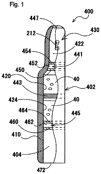
In operation, the pressurized liquid gas mixture enters nozzle orifice 304, through fluid pathway 306. The pressurized liquid gas mixture is accelerated through passage 306, forcing it into intermediate chamber 310. This action begins the process of mixing of the gas and liquid and the breaking up of the gas bubbles into micro bubbles. The process continues as the pressurized liquid and gas mixture travels through passages 312, 316, 314a and 314b. The liquid containing micro bubbles is expelled into the fluid dispensing fitting or plumbing through passages 314a and 314b. Passages 312, 316, 314a and 314b have distal openings for releasing the plurality of micro bubbles downstream of the chamber 310 and fluid passages 306. It is understood that the air-water interaction allows creation of a high pressure micro bubble matrix or micro bubble cloud 400 (See FIG. 1). As can be appreciated, the velocity of the bubbles 400 and iconic nature of the micro bubble sweeps away the impurities and debris from the end-user or surfaces of an object being engaged by the micro bubble matrix. The effective cleaning of the surfaces provides an improved cleaning benefit.
FIG. 7 illustrates an alternative construction of a micro bubble apparatus 1300. Micro bubble apparatus 1300 has a similar construction as micro bubble apparatus 300, except for the construction of a fluid pathway 314. While two pathways 314a and 314b may be used in apparatus 300, the inventive aspect may be practiced with only a single pathway 314 to release the micro bubbles. Pathway 314 is directly connected to and is oriented perpendicular to the fluid pathway 316 and 312.
FIG. 8 illustrates yet another alternative construction of a micro bubble apparatus 2300. Micro bubble apparatus 2300 has a similar construction as micro bubble apparatus 300, except for the construction of a fluid pathway 306. While only a single pathway 306 is used in apparatus 300, the inventive aspects may be practiced with two pathways 306a and 306b.
FIG. 9 illustrates yet another alternative construction of a micro bubble apparatus 3300. Micro bubble apparatus 3300 has a similar construction as micro bubble apparatus 300, except for the construction of a fluid pathway 306, 314 and 316. While only a single pathway 306 is used in apparatus 300, the inventive aspects may be practiced with two pathways 306a and 306b. While two pathways 314a and 314b may be used in apparatus 300, the inventive aspects may be practiced with only a single pathway 314 to release the micro bubbles. Furthermore, while two pathways 312 and 316 are provided in apparatus 300, the inventive aspects may be practiced with only a single pathway 312. The angular orientation of the pathways causes the gas bubbles suspended in the liquid to crash into the internal walls of the pathways before expelling the liquid and gas mixture into a liquid dispensing fitting, such as a jet, or dispensing plumbing. The dispensing action promotes a dense and stable micro bubble cloud by breaking the gas bubbles into smaller micro bubbles and preventing the bubbles from coalescing.
As shown in FIGS. 6-9, the inventive aspects may be practices with assemblies of different types of housings configurations and different types of orifice nozzles. It is recognized that individual features and sub-combinations of these features can be used to obtain some of the aforementioned advantages without the necessity to adopt all of these features.
In alternative constructions using the inventive concepts herein, the micro bubble generating apparatus 300, 1300, 2300 and 3300 can be embodied in a form of a replaceable internal cartridge assembly. The cartridge forms a micro bubble cloud as the pressurized liquid and gas mixture passes through it into a bath well, for example. The micro bubble cartridge assembly can be installed into fitting that is used for directing the flow of fluids such as hydrotherapy jets, shower heads, or liquid/water nozzles. Each fitting may contain a cartridge comprising an inlet and outlet orifice and passages that create the micro bubbles. Referring to FIGS. 10 through 13, the bubble generating apparatus 300, 1300, 2300, and 3300 may be provided with various fluid dispensing fittings such as a hydrotherapy jet assembly 500, hand held shower assembly 600, shower head assembly 700, and water nozzle assembly 800.
The description continues in the full USPTO document.
 Lapsed, fee not paid9 drawings