Field of the invention
The invention relates generally to impact attenuating and spring elements. Such elements may be provided in a wide variety of different products, e.g., in footwear products and other foot-receiving devices, such as in the heel and/or toe areas of footwear products. This application generally relates to impact attenuating elements like those described in concurrently filed U.S. patent application Ser. No. 10/949,813, entitled "Impact Attenuating Devices and Products Containing Such Devices," naming Michael Aveni as an inventor. This concurrently filed U.S. patent application is entirely incorporated herein by reference.
Background
Conventional articles of athletic footwear have included two primary elements, namely an upper and a sole member or structure. The upper provides a covering for the foot that securely receives and positions the foot with respect to the sole structure. In addition, the upper may have a configuration that protects the foot and provides ventilation, thereby cooling the foot and removing perspiration. The sole structure generally is secured to a lower portion of the upper and generally is positioned between the foot and the ground. In addition to attenuating ground reaction forces (i.e., imparting cushioning), the sole structure may provide traction and control foot motions, such as pronation. Accordingly, the upper and the sole structure operate cooperatively to provide a comfortable structure that is suited for a variety of ambulatory activities, such as walking and running.
The sole member or structure of athletic footwear generally exhibits a layered configuration that includes a comfort-enhancing insole, a resilient midsole formed from a polymer foam material, and a ground-contacting outsole that provides both abrasion-resistance and fraction. The midsole is the primary sole structure element that attenuates ground reaction forces and controls foot motions. Suitable polymer foam materials for the midsole include ethylvinylacetate or polyurethane that compress resiliently under an applied load to attenuate ground reaction forces. Conventional polymer foam materials are resiliently compressible, in part, due to the inclusion of a plurality of open or closed cells that define an inner volume substantially displaced by gas.
As noted above, various impact attenuating elements and systems have been known, including such elements and systems for use in footwear products. Conventionally, the insole, midsole, and/or outsole portions of footwear products may include foam or other materials that attenuate shock and dampen vibrations, e.g., in the heel and/or toe areas of a shoe. In at least some instances, a relatively large volume of foam or other material may be needed to fully or sufficiently attenuate the impact force to which footwear products are subjected and to provide sufficient support and/or comfort. This is particularly true for athletic footwear, which may be subjected to relatively high impact forces, e.g., from running, jumping, twisting, changing directions, participating in athletic field events, and the like. An excessively high volume of impact attenuating material, if necessary to adequately attenuate ground reaction forces and/or provide support, may make the shoe stand too tall vertically, particularly for use as an athletic shoe.
Moreover, even when conventional foam materials provide adequate impact attenuation and comfort properties for use in footwear products, these materials do little or nothing in returning energy back to the footwear user. Rather, foam materials typically recover from compression and return to their original shape relatively slowly and with little or no return or "spring-back". Additionally, if a compression force persists on the foam material, this force may further prevent or slow the material's recovery.
Accordingly, it would be useful to provide an impact attenuating element that attenuates impact forces (e.g., ground reaction forces), and provides return or "spring-back" energy, e.g., for use in footwear products and/or other foot-receiving devices. Advantageously, such impact attenuating and spring elements will provide these useful properties without excessively adding to the height of the footwear or other product.
Summary
The following presents a general summary of aspects of the invention in order to provide a basic understanding of at least some aspects of the invention. This summary is not an extensive overview of the invention. It is not intended to identify key or critical elements of the invention or to delineate the scope of the invention. The following summary merely presents some concepts of the invention in a general form as a prelude to the more detailed description provided below.
Aspects of this invention relate to impact attenuating and spring elements and systems and products in which they are used (such as footwear, other foot-receiving devices, and the like). In at least some examples, impact attenuating and spring elements in accordance with this invention will attenuate a component of an incident impact force from a first direction (e.g., a vertical force component), which action induces a corresponding displacement of at least a portion of the element in a different direction (e.g., a horizontal displacement). Additionally, the displacement may be used to "load" a spring member (e.g., stretch a horizontally arranged spring member), which then quickly returns to its original, unloaded orientation, releasing at least some energy back in a direction opposite to the original direction of the impact force.
Impact attenuating and spring elements in accordance with at least some example aspects of this invention may include, for example: (a) a first body portion; (b) a second body portion, wherein the first body portion and the second body portion, at least in part, define a base orientation of the impact attenuating and spring element, and wherein an open space is defined between the first and second body portions; and (c) one or more spring members, optionally at least partially included in the open space, and pivotally engaged with respect to at least one of the first body portion or the second body portion. The various portions of the impact attenuating and spring element may be arranged such that when a force is applied to at least one of the first body portion or the second body portion so as to change the impact attenuating and spring element out of the base orientation (e.g., compress the body portions together), the spring member(s) will exert a counter force that urges the impact attenuating and spring element back toward the base orientation. The spring members may include, for example, at least one polymeric element that stretches under a tensile force and returns to its original shape and/or size (or substantially its original shape and/or size) when the force is released.
Aspects of the invention also relate to impact attenuating and spring elements that include, for example: (a) a first arched body portion; (b) a second arched body portion facing the first arched body portion such that an open space is defined between the body portions; and (c) a spring member at least partially included in the open space and extending to at least substantially contain the first arched body portion and the second arched body portion. In this example impact attenuating and spring element, when a force is applied to at least one of the first arched body portion or the second arched body portion so as to change an orientation of the impact attenuating and spring element, the first spring member exerts a force that urges the impact attenuating and spring element back toward its original orientation. In at least some examples, at least one edge of one or both of the arched body portions may be rounded so as to allow a pivotal engagement between the arched body portion(s) and the spring member.
Impact attenuating and spring elements of the type described above may be included in pieces of footwear and/or other foot-receiving devices in accordance with additional aspects of this invention.
Additional aspects of the invention relate to methods for including impact attenuating and spring elements in products, such as in pieces of footwear or other foot-receiving devices. Such methods may include, for example: (a) providing an upper member and a sole member for a piece of footwear or other foot-receiving device; (b) selecting at least a portion of an impact attenuating and spring element (e.g., at least a spring member) at least in part based on a characteristic of an intended user of the piece of footwear or other foot-receiving device (e.g., user weight, foot width, running/walking speed capabilities, jumping capabilities, typical gait or stride characteristics (e.g., a pronation or supination tendency, etc.), etc.), or a characteristic of an intended use of the piece of footwear or other foot-receiving device (e.g., for a specific sport or training type); and (c) providing at least the portion of the impact attenuating and spring element between the upper member and the sole member of the piece of footwear or other foot-receiving device and/or engaging at least the portion of the impact attenuating and spring element with at least one of the upper member or the sole member. The impact attenuating and spring elements and/or the portions thereof may be of the type described generally above, and one or more of them may be freely removed or replaced in the piece of footwear or other foot-receiving device, for example, at a point of sale location (e.g., depending on characteristics of the intended user or its ultimate intended use), at a warehouse, at a manufacturing location, or by the user (e.g., at a point of use location, depending on the desired characteristics at a given time, for a given use, etc.).
Brief description of the drawings
A more complete understanding of the present invention and certain advantages thereof may be acquired by referring to the following description in consideration with the accompanying drawings, in which like reference numbers indicate like features, and wherein:
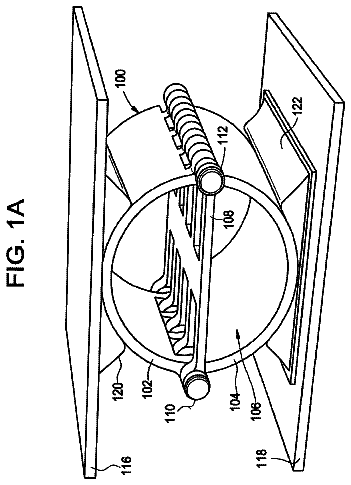
FIGS. 1A and 1B illustrate an example impact attenuating and spring element in accordance with aspects of this invention;
FIGS. 2A through 2C illustrate another example impact attenuating and spring element in accordance with aspects of this invention;
FIG. 3 illustrates another example impact attenuating and spring element in accordance with aspects of this invention;
FIGS. 4A and 4B illustrate another example impact attenuating and spring element in accordance with aspects of this invention;
FIGS. 5A through 5C illustrate an example impact attenuating and spring element/base member structure in accordance with aspects of this invention;
FIGS. 6A through 6C illustrate an example impact attenuating and spring element with separate hinge members in accordance with aspects of this invention;
FIGS. 7A through 7D illustrate another example impact attenuating and spring element with separate hinge members and cam action in accordance with aspects of this invention;
FIGS. 8A through 8C illustrate an example impact attenuating and spring element with a spring member that at least partially encloses the body portions of the element in accordance with aspects of this invention;
FIGS. 9A through 9C illustrate another example impact attenuating and spring element with a spring member that at least partially encloses the body portions of the element in accordance with aspects of this invention;
FIGS. 10A and 10B illustrate another example impact attenuating and spring element in accordance with aspects of this invention; and
FIG. 11 illustrates an example piece of footwear or other foot-receiving device including impact attenuating and spring elements at various locations in accordance with this invention.
Detailed description
In the following description of various examples of the invention, reference is made to the accompanying drawings, which form a part hereof, and in which is shown by way of illustration various example systems and environments in which the invention may be practiced. It is to be understood that other specific arrangements of parts, example systems, and environments may be utilized and structural and functional modifications may be made without departing from the scope of the present invention. Also, while the terms "top," "bottom," "side," "front," "back," and the like may be used in this specification to describe various example features and elements of the invention, these terms are used herein as a matter of convenience, e.g., based on the example orientations shown in the figures. Nothing in this specification should be construed as requiring a specific three dimensional orientation of structures in order to fall within the scope of this invention.
To assist the reader, this specification is broken into various subsections, as follows: Terms; General Description of Impact Attenuating and Spring Systems According to the Invention; Specific Examples of the Invention; and Conclusion.
A. Terms
The following terms are used in this specification, and unless otherwise noted or clear from the context, these terms have the meanings provided below.
"Foot-receiving device" means any device into which a user places at least some portion of his or her foot. In addition to all types of footwear (described below), foot-receiving devices include, but are not limited to: bindings and other devices for securing feet in snow skis, cross country skis, water skis, snowboards, and the like; bindings, clips, or other devices for securing feet in pedals for use with bicycles, exercise equipment, and the like; bindings, clips, or other devices for receiving feet during play of video games or other games; and the like.
"Footwear" means any type of wearing apparel for the feet, and this term includes, but is not limited to: all types of shoes, boots, sneakers, sandals, thongs, flip-flops, mules, scuffs, slippers, sport-specific shoes (such as golf shoes, tennis shoes, baseball cleats, soccer or football cleats, ski boots, etc.), and the like.
B. General Description of Impact Attenuating and Spring Systems According to the Invention
In general, aspects of this invention relate to impact attenuating and spring systems, products in which they are used (such as footwear, other foot-receiving devices, and the like), and methods for including them in footwear, foot-receiving devices, and the like. Impact attenuating and spring elements in accordance with at least some example aspects of this invention may include, for example: (a) a first body portion; (b) a second body portion, wherein the first and second body portions, at least in part, define a base orientation of the impact attenuating and spring element, and wherein an open space is defined between the first and second body portions; and (c) a first spring member at least partially included in the open space and pivotally engaged with respect to at least one of the first body portion or the second body portion. The various portions of the impact attenuating and spring element may be arranged such that when a force is applied to at least one of the first body portion or the second body portion so as to change the impact attenuating and spring element out of its base orientation (e.g., a vertical compressive force from stepping down on a shoe, landing a jump, etc.), the first spring member will displace in another direction (e.g., stretch in a horizontal direction) and then will exert a counter force that urges the impact attenuating and spring element back toward the base orientation.
Devices in accordance with at least some examples of this invention may include more than one spring member of the type described above. The spring members may include, for example, at least one polymeric element that stretches under a tensile force and returns to its original shape and/or size (or substantially its original shape and/or size) when the force is released.
The spring member(s) may be located at any suitable or desired location in the impact attenuating and spring element without departing from the invention. For example, in some impact attenuating and spring elements according to the invention, the spring member(s) may extend across the open space at a central location between the first and second body portions. As another example, in some impact attenuating and spring elements according to the invention, one or more spring members may extend across the open space at a location proximate to a central portion of one of the body portions (optionally, if desired, one or more additional spring members may extend across the open space at a location proximate to a central portion of the other body portion). In still other examples, the spring member(s) may be located outside the open space defined by the body portions. Combinations of these various spring member positions and orientations also may be used without departing from this invention.
The pivotal engagement between the spring member(s) and at least one of the body portions also may be provided in any suitable or desired manner without departing from the invention. For example, impact attenuating and spring elements in accordance with at least some examples of this invention may include a first shaft connecting the first body portion, the second body portion, and the first spring member in a pivotal manner at a first location and a second shaft connecting the first body portion, the second body portion, and the first spring member in a pivotal manner at a second location (e.g., a shaft along each side edge of the first and second body portions and the spring member(s)). The first and second body portions and the spring member(s) also may be connected to one another at one or multiple locations along their side edges. As another example, independent hinge members may be provided to pivotally engage the body portions with the spring member(s). As still another example, one spring member may be pivotally engaged with one body portion and a second spring member may be pivotally engaged with another body portion. In yet another example impact attenuating and spring element in accordance with aspects of the invention, one or more of the body portions may include rounded edges that provide the pivotal engagement with the first spring member under the incident force being attenuated. Other arrangements and/or combinations of the above arrangements also are possible without departing from this invention.
Aspects of the invention also relate to impact attenuating and spring elements that include, for example: (a) a first arched body portion; (b) a second arched body portion facing the first arched body portion, wherein an open space is defined between the body portions; and (c) a first spring member at least partially included in the open space and extending to at least substantially contain the first arched body portion and the second arched body portion. In this example impact attenuating and spring element, when a force is applied to at least one of the first or second arched body portions so as to change an orientation of the impact attenuating and spring element, the first spring member exerts a force that urges the impact attenuating and spring element back toward its original orientation. Optionally, impact attenuating and spring elements in accordance with these aspects of the invention further may include: (d) a third arched body portion; and (e) a fourth arched body portion facing the third arched body portion, wherein a second open space is defined between the third and fourth arched body portions, wherein the first spring member is at least partially included in the second open space and extends to at least substantially contain the third and fourth arched body portions. In at least some examples, at least one edge of one or both of the arched body portions may include rounded edges that allow pivotal engagement between the arched body portion(s) and the spring member.
As used in this specification in this context, the term "substantially contain" means that a majority (at least 50%) of the exterior surface area of the body portion is covered by or contained within an area or volume defined by the spring member.
Optionally, in at least some examples of the invention, some parts of the first and second arched body portions may extend through the first spring member, e.g., to provide a peg or other means for engaging with a base or other element and/or to help secure the body portion to the spring member.
Still additional aspects of the invention relate to impact attenuating and spring elements that may include: (a) a first body portion; (b) a second body portion facing the first body portion, wherein an open space is defined between the body portions; (c) a first spring member at least partially included in the open space; and (d) a hinge member connecting the first body portion and the second body portion, wherein the spring member engages a cam portion of the hinge member. In this example, when a force is applied to at least one of the first or second body portions so as to change an orientation of the impact attenuating and spring element, the first spring member exerts a force that urges the element back toward its original orientation. In at least some examples of the invention, the first spring member may extend outside the open space through an area defined between the first body portion and the cam portion of the hinge member. In use, the spring member may slidably move with respect to the first body portion.
Additional aspects of the invention relate to pieces of footwear or other foot-receiving devices that include one or more of the impact attenuating and spring elements described above. Such pieces of footwear or foot-receiving devices may include, inter alia: (a) an upper member; (b) a sole member connected directly or indirectly to the upper member; and (c) at least one impact attenuating and spring element like those described above located between the upper member and the sole member and/or engaged with at least some portion of at least one of the upper member or the sole member. The impact attenuating and spring element(s) may be located in the heel area of the piece of footwear or other foot-receiving device, in the toe area, and/or in any other suitable or desired location without departing from this invention. In some examples, the impact attenuating and spring element(s) will remain visible and exposed, even after assembly of the footwear or foot-receiving device is completed and/or while the footwear or foot-receiving device is in use, although the impact attenuating and spring elements may be enclosed in the structure without departing from the invention.
Still additional aspects of the invention relate to methods for including one or more impact attenuating and spring elements in a piece of footwear or foot-receiving device. Such methods may include, for example: (a) providing an upper member and a sole member for a piece of footwear or foot-receiving device; (b) selecting at least a portion of an impact attenuating and spring element at least in part based on a characteristic of an intended user of the piece of footwear or foot-receiving device or based on a characteristic of an intended use of the piece of footwear or foot-receiving device; and (c) providing at least the portion of the impact attenuating and spring element between the upper member and the sole member of the piece of footwear or foot-receiving device and/or engaging at least the portion of the impact attenuating and spring element with at least one of the upper member or the sole member. The impact attenuating and spring elements or portions thereof may be of the type described above (and described in more detail below).
As more specific examples, the portion of the impact attenuating and spring element may be selected based on one or more characteristics of the intended end user, such as: the user's weight, the user's shoe size, the user's foot width, the user's moving speed or anticipated moving speed, the user's typical gait or stride characteristics (e.g., a pronation or supination tendency), and the like. Also, different impact attenuating and spring elements or portions thereof may be selected depending on the final intended end use of the footwear or foot-receiving device products. For example, different impact attenuating and spring elements or portions thereof (e.g., having different stiffnesses) may be selected depending on whether the product is used for walking, running, basketball, soccer, football, baseball, softball, sprinting, track events, field events, children's games, video games, etc.
The impact attenuating and spring elements or portions thereof also may be selected and/or included as part of the footwear or foot-receiving device structure at any desired location without departing from the invention. For example, the impact attenuating and spring elements or portions thereof may be selected at the assembly factory, and the products then may be marketed in a manner targeted to specific intended user or use characteristics (e.g., the sales box or a tag on the product might indicate that the shoe is designed for running or jogging for a user between 165 and 180 lbs.). As another example, shoe retailers or wholesalers may have a supply of impact attenuating and spring elements or portions thereof to insert into the footwear or foot-receiving device at the point of sale location, e.g., based on the characteristics of the intended user and/or the intended use, to replenish depleted stock, etc. As still another example, users may be allowed to freely select and/or change impact attenuating and spring elements or portions thereof, based on their immediate needs or the characteristics they desire in the footwear or other foot-receiving device (e.g., by switching one impact attenuating and spring element or portion thereof for another at a point of use location, etc.).
Specific examples of the invention are described in more detail below. The reader should understand that these specific examples are set forth merely to illustrate examples of the invention, and they should not be construed as limiting the invention.
C. Specific Examples of the Invention
The various figures in this application illustrate examples of impact attenuating and spring elements useful in systems and methods according to examples of this invention. When the same reference number appears in more than one drawing, that reference number is used consistently in this specification and the drawings to refer to the same or similar parts throughout.
FIGS. 1A and 1B illustrate a first example impact attenuating and spring element or device 100 in accordance with aspects of this invention. This example impact attenuating and spring element 100 (also called a "spring device" in this specification) includes a first body or housing portion or member 102 and a second body or housing portion or member 104, wherein the body members 102 and 104 are arranged facing one another such that an open space 106 is defined between them. The body members 102 and 104 in the illustrated example are arched, semicircular, semi-oval (with a flat or substantially flat top edge), semi-elliptical, hemispherical, etc., in shape so as to provide an area for open space 106, although any suitable shape or orientation may be used without departing from this invention. The body members 102 and 104 may be made from any suitable material, such as plastic, elastomeric, or polymeric materials capable of changing shape, size, and/or orientation when a force is applied thereto and returning back to or toward their original shape, size, and/or orientation when the force is relieved or relaxed. As a more specific example, the body members 102 and 104 (as well as the body portions or members of other examples described in this specification) may be made from a polymeric material, such as PEBAX.RTM. (a polyether-block co-polyamide polymer available from Atofina Corporation of Puteaux, France). If desired, a single piece body member may be used that includes body portions that define an open area, or the individual body members 102 and/or 104 each may be constructed from multiple pieces, without departing from this invention.
As illustrated in FIG. 1A, the body members 102 and 104, at least in part, define a base or neutral orientation for the spring device 100 (e.g., an orientation at which no significant external forces are applied to the spring device 100 other than forces applied by the components of the device 100 and/or the components of any device in which it is mounted or housed (such as a piece of footwear or other foot-receiving device)). In other words, in its base or neutral orientation, no external force is applied to the spring device 100 by the user, for example, as a result of walking, running, or jumping (although the spring device 100 may support the user's weight and still be considered as in its neutral or base orientation).
A spring member 108 extends across and is at least partially included in the open space 106. In the base orientation, as illustrated in FIG. 1A, the spring member 108 tautly extends across the open space 106 defined between the body members 102 and 104 at essentially a central location between the body members 102 and 104. In at least some examples of the invention, forces applied to the overall spring device structure 100 by the spring member 108 may be included as part of the forces that define the base or neutral orientation for the spring device 100.
Any suitable or desired spring member 108 design or orientation may be included in the spring device 100 structure without departing from this invention. In this illustrated example, the spring member 108 is a synthetic or natural rubber or polymeric material (such as an elastomeric material) that is capable of stretching under tensile force and then returning (or substantially returning) to or toward its original size and shape when the force is relieved or relaxed. As a more specific example, the spring member 108 (as well as the spring members of other examples described in this specification) may be made from a polymeric material, such as DESMOPAN.RTM. (a thermoplastic polyurethane material available from Bayer AG of Leverkusen, Germany). The size, construction, orientation, material, and/or other properties of the spring member 108 may be freely selected and varied to change the overall stiffness and spring constant characteristics of the spring device 100.
The spring member 108 may be engaged with respect to at least one of the body members 102 and/or 104 in a pivotal, rotatable, or hinged manner. In the example illustrated in FIGS. 1A and 1B, the spring member 108 is pivotally connected to both body member 102 and body member 104, at multiple locations, by two pivot shafts 110 and 112 (e.g., the shafts 110 and 112 extend through openings defined along the connecting edges of body member 102, body member 104, and spring member 108). The pivot shafts 110 and 112 may be made of metal, plastic, composites, and/or any other suitable or desired material. In this manner, when a force is applied to at least one of the body members 102 or 104 in a first direction (e.g., a compressive vertical force 114 that tends to reduce at least one dimension of the open space 106) so as to change the spring device 100 from its base orientation (as shown in FIG. 1A) to a compressed or loaded orientation (as shown in FIG. 1B), the spring member 108 will stretch. In other words, the compressive force 114 is attenuated, thereby causing a displacement in another direction (e.g., a horizontal stretch of spring member 108). The spring member 108 may remain stretched while the load 114 is applied. The pivotal or hinged connection allows the body members 102 and 104 and the spring member 108 to more freely move with respect to one another and helps prevent stresses induced by the compressive force 114 from breaking one of the body members 102 or 104 or the spring member 108, particularly at or near their points of connection. When the load 114 is relieved or relaxed, the spring member 108 will return to (or substantially return to) its original size and shape (e.g., see FIG. 1A), which tends to pull the body members 102 and 104 inward, thereby returning the spring device 100 to its original orientation (or at least back toward its original orientation). Material characteristics of the body members 102 and 104 (e.g., their thermoplastic construction in some examples) also may help return the body members 102 and 104 to their original orientation.
Forces may be applied to the spring device 100 in any suitable manner or under any set of circumstances without departing from aspects of this invention. As one more specific example, one or more of the spring devices 100 may be mounted in a piece of footwear or other foot-receiving device (e.g., as part of a midsole or outsole in the heel and/or toe areas of the piece of footwear or other foot-receiving device), and compressive forces 114 (e.g., ground reaction forces) may be applied to the spring device 100 as the user steps down on the footwear or other foot-receiving device (e.g., while stepping, landing from a jump, etc.). Because of the spring back forces applied when spring member 108 returns to its original size, shape, and orientation, the spring device 100 may assist in the user's step or jump rebounding effort, thereby improving or enhancing the user's performance.
FIGS. 1A and 1B further illustrate the spring device 100 mounted or included between two bases or plates 116 and 118, wherein optional flexible interfaces 120 and 122 (such as foam material) are provided between the bases 116 and 118 and the body members 102 and 104 of the spring device 100. These flexible interfaces 120 and 122 may be capable of changing shape when the compressive forces 114 are applied, as shown in FIGS. 1A and 1B.
The bases 116 and 118 and optional flexible interfaces 120 and 122 may form an integral part of a piece of footwear or other device in which the spring device 100 may be mounted or included. Alternatively, the bases 116 and 118 and optional flexible interfaces 120 and 122 may be included as part of the overall spring device 100 and placed in a piece of footwear or other device along with the other elements of the spring device 100 as a unitary construction (e.g., as a "heel cage" unit). The flexible interfaces 120 and 122 may be attached to their respective bases 116 and 118, if desired, and the body members 102 and 104 may be attached to their respective interfaces 120 and 122, if desired, and/or bases 116 and 118, in any suitable manner, such as through a mechanical connection, an adhesive connection, a tight fit, or the like.
The bases 116 and 118 may be made from any desired material without departing from the invention. As a more specific example, the bases 116 and 118 (as well as the bases of other examples described in this specification) may be made from a polymeric material, such as PEBAX.RTM. (a polyether-block co-polyamide polymer available from Atofina Corporation of Puteaux, France). The flexible interfaces 120 and 122 also may be made from any suitable or desired material, such as a commercially available synthetic foam rubber material or the like.
While the specific example illustrated in FIGS. 1A and 1B includes shafts 110 and 112 to allow rotational or pivotal movement of the body members 102 and 104, e.g., with respect to spring member 108 and with respect to one another, other arrangements are possible that do not require the use of shafts 110 and 112. Additionally, while the structure shown in FIGS. 1A and 1B is made up of multiple independent pieces, more unitary and/or one-piece constructions for at least portions of the impact attenuating devices 100 are possible without departing from the invention. Some examples of such arrangements and structures are described in more detail below.
FIGS. 2A through 2C illustrate another example of a spring device 200 in accordance with aspects of this invention that includes additional or alternative potential features or structures. As illustrated in FIG. 2A, the spring device 200 includes a first body portion or member 202 and a second body portion or member 204 shaped and oriented so as to face one another and to provide an open area 206 therebetween. In this example, the body members 202 and 204 are more semi-oval or semi-elliptical shaped in their base orientation as compared to the body members 102 and 104 of FIGS. 1A and 1B. Also, in this example, plural independent spring members 208 are provided and extend across the open area 206 at a central location between the body members 202 and 204. The spring members 208 are pivotally or hingedly mounted with respect to both body members 202 and 204 along their respective connecting edges by shafts 210 and 212 in a manner similar to that illustrated in FIGS. 1A and 1B. Additionally, when a compressive force is applied to the body members 202 and 204, the spring device 200 and spring members 208 operate in a similar manner to spring device 100 and spring member 108 described above.
While not a requirement, all of the spring members 208 in this example are identically shaped and sized, although different shapes, sizes, strengths, and materials may be used for the individual spring members 208 without departing from the invention. Additionally, although FIGS. 2A and 2B illustrate all of the spring members 208 arranged in parallel, in a common plane across essentially the center of the spring device 200, any suitable or desired arrangement or orientation of the spring members 208 may be used without departing from this invention, including arrangements in different planes and/or in a non-parallel manner. Again, the size, construction, orientation, material, and/or other properties of the various individual spring members 208 may be freely selected and varied to change the overall stiffness and spring constant characteristics of the spring device 200. Additionally, if desired, one or more spring members 208 may be used in combination with spring members of other sizes, constructions, orientations, materials, and/or other properties without departing from the invention.
Additional features available in accordance with at least some examples of this invention are illustrated in FIGS. 2A through 2C. For example, each of the body members 202 and 204 in this illustrated example include mountings members 214. These mounting members 214 (e.g., pins 214 in the illustrated example) may be used to fix the locations of the body members 202 and 204 with respect to base members 216 and 218, as illustrated in FIG. 2C. Optionally, an adhesive or cement, e.g., on mounting members 214, on base members 216 and 218, and/or on body members 202 and 204, may be used to further secure the body members 202 and 204 to their respective base member 216 and 218, if desired. The base members 216 and 218 may form an integral part of the spring device 200, or alternatively, they may form a part of a device that will contain the spring device 200 (such as a piece of footwear or other foot-receiving device) without departing from the invention. Additionally, while the mounting pins 214 are shown as round pegs in FIGS. 2A through 2C, any suitable or desired structure, position, shape, or size for the attachment elements may be used without departing from the invention. For example, the outer surface of the body members 202 and 204 may include one or more raised ribs that fit into slots, tracks, or openings formed in the base members 216 and 218, and vice versa.
The description continues in the full USPTO document.
 Lapsed, fee not paid9 drawings