Background of the invention
1. Field of the invention
The present invention relates to an image forming apparatus for correcting a position deviation of an image to be formed.
2. Description of the related art
A position deviation (color deviation) is known as a problem in a color image forming apparatus of a tandem system. The tandem system is a system which is provided with developing machines and photosensitive elements each number of which is the same as the color number of the toner and sequentially transfers images in different colors onto a carrier belt or a print medium. The position deviation means the event that the image is made to be transferred in a position different from a position to be expected. A cause of the position deviation is unevenness or a mounting position deviation of a lens in a deflection scan apparatus, or an assembling position deviation of the deflection scan apparatus to a color image forming apparatus body. Caused by this position deviation, an inclination or a curve is generated in a scan line and a degree of the inclination or curve differs in each color, thus creating the position deviation (color deviation) of the image.
An example of the method for overcoming this problem includes a method in which magnitudes of an inclination and a curve in a scan line are measured by using an optical sensor and the bit map image data is corrected to cancel out the magnitudes, forming the corrected image (Japanese Patent Laid-Open No. 2004-170755).
In general, a color image forming apparatus forms a pattern for position deviation detection for each color on an image carrier such as a photosensitive element or an intermediate transfer element or on a transfer material carrier such as a carrier belt and detects the formed pattern by optical sensors located at both sides in the downstream portion. Further, correction of the position deviation is made based upon the detection result.
However, in a case where the pattern for position deviation detection is formed on the transfer material carrier by the position deviation correcting method using the process described in Japanese Patent Laid-Open No. 2004-170755, in some cases the detection accuracy of the pattern is deteriorated. Hereinafter, the reason for the deterioration of the detection accuracy will be explained.
In a case of finding a position deviation (color deviation) using a pattern for position deviation detection, a pattern configured by horizontal lines, inclined lines or the like is formed, a position of the line in the pattern is detected by a scan of an optical sensor on the line, and the position deviation is calculated based upon the detected position of the line. FIG. 11A shows an example of a pattern for position deviation detection to be formed on a transfer material carrier. K1 and K2 are patterns for position deviation detection formed in black, and Y is a pattern for position deviation detection formed in yellow. Respective detection timings of lines in the patterns K1, K2, and Y by the optical sensor are defined as t1, t2, and t3 and a conveying speed of an intermediate transfer element is defined as v. Then the position deviation in a sub scan direction between the black and yellow patterns can be found according to the formula of {t3-(t1+t2)/2}.times.v. The position deviation in the sub scan direction means a deviation in an arrow direction (scan line direction of the optical sensor) of FIG. 11A. The patterns in this example are configured only by the black and yellow patterns, but a position deviation in a sub scan direction between similar patterns in other colors can be also found.
The detection timing of each line is found by a signal from the optical sensor. FIG. 11B shows horizontal lines formed as a part of the pattern for position deviation detection and a scan line of the optical sensor, and FIG. 11C expresses a signal from the optical sensor in a case of detecting the horizontal line in FIG. 11B along the scan line. As shown in FIG. 11C, timings where the signal and a threshold value (for example, threshold value of the density) intersect are defined as detection timings of edges in the line and the detection timings at both ends of the line are averaged, thus finding a detection timing of a center position of the line in a sub scan direction. The detection timing in the center position is defined as the detection timing of the line.
Here, in a case of detecting the pattern for position deviation detection to which the position deviation correction using the process described in Japanese Patent Laid-Open No. 2004-170755 is made, based upon the method as described above, there possibly occurs a problem that the detection accuracy is deteriorated. This problem will be explained with reference to FIGS. 12A and 12B.
FIG. 12A shows an image forming state in a case where the position deviation correction is made to the horizontal line, and FIG. 12B shows a detection signal in a case of detecting the line in FIG. 12A by the optical sensor. As shown in FIG. 12A, in a case where the position deviation correction is made, a pixel smaller than one pixel is used at an edge portion of the line in addition to the correction in a pixel unit. Details of the correction method are described in Japanese Patent Laid-Open No. 2004-170755.
Here, since it is generally difficult to stably form a small pixel due to the influence of the fluidity in a toner in an image forming apparatus of an electronic photography system, the edge portion of the line configured by the small pixel tends to be easily unstable.
In a case of forming the small pixel, when an optical amount at exposure is made small or exposure hours are shortened, a latent image is made shallow and therefore an applied amount of the toner is unstable. Therefore, as compared to an ideal detection signal shown in a dotted line in FIG. 12B, the edges of the line are detected to be deviated in an actual detection signal shown in a solid line. As a result, since the aforementioned center position of the line is also calculated to be deviated, the detection accuracy of the pattern for position deviation detection is deteriorated.
In addition, not limited to the aforementioned correction, for example, even in a case of making a correction in a pixel unit alone, caused by the correction a defect possibly occurs in the position deviation detection result. For example, that is a case where position deviation detection patterns to be formed overlap. In this way, in a case where a digital position deviation correction of correcting the image data itself is made in a sub scan direction, the defect occurs in the detection result of the pattern for position deviation detection.
Summary of the invention
The present invention forms a pattern for position deviation detection in such a manner as to be accurately detectable in an image forming apparatus for making a position deviation correction.
The present invention is provided with an image forming apparatus comprising an image position correcting unit for making a position correction of an image in a sub scan direction to image data, wherein the position correction includes a position correction for less than one pixel and a position correction in one pixel unit, an image forming unit for forming a pattern for position deviation detection as the image data to which the position correction is made, a detecting unit for detecting the formed pattern for position deviation detection, a position deviation amount calculating unit for calculating a position deviation amount of the image data based upon the detected pattern for position deviation detection, and a control unit for controlling the forming unit to form the pattern for position deviation detection without making the position correction of the image for less than one pixel by the image position correcting unit to a pattern formed in the vicinity of a detection region of the detecting unit and for controlling the position deviation amount calculating unit to calculate the position deviation amount using a value of the position correction which is not made to the formed pattern for position deviation detection.
According to the present invention, it is possible to improve calculation accuracy of the position deviation amount in the image forming apparatus for making the position deviation correction.
Further features of the present invention will become apparent from the following description of exemplary embodiments (with reference to the attached drawings).
Brief description of the drawings
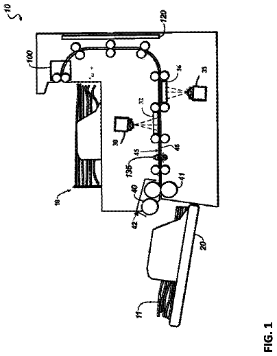
FIG. 1 is a cross section showing an embodiment of a color image forming apparatus;
FIG. 2 is a functional block diagram of the color image forming apparatus and a diagram showing an embodiment of signal processing in the functional block diagram;
FIG. 3 is a diagram showing a relation between a position deviation amount and a position deviation correction amount .DELTA.y of an image in a sub scan direction to each position in a main scan direction in a case where a scan line is inclined or curved;
FIGS. 4A to 4F are diagrams explaining an embodiment of an image correction at the time of forming a normal image;
FIG. 5 is a diagram showing an example of a pattern for position deviation detection formed on a transfer material carrier;
FIG. 6 is a flow chart for switching processing of an image correcting method;
FIG. 7 is a diagram explaining the event that a step of a line is generated in a case of making an image correction without smoothing;
FIG. 8 is a diagram explaining a position relation between a detection pattern and a step restricting region;
FIGS. 9A to 9E are diagrams explaining an embodiment of an image correction at the time of forming a detection pattern;
FIG. 9F is a diagram explaining a state of the pattern formation in a case smoothing processing of less than one pixel and offset processing in one pixel unit are not executed;
FIG. 9G is an example where the smoothing processing of less than one pixel is not executed and the offset processing in one pixel unit is executed to a region other than a step restricting region;
FIGS. 10A and 10B are diagrams explaining a difference in position deviation detection accuracy by each image correcting method;
FIGS. 11A to 11C are diagrams explaining position deviation detection between patterns in two colors in a sub scan direction;
FIGS. 12A and 12B are diagrams showing a detection signal in a case of detecting a horizontal line after position deviation correction by an optical sensor;
FIG. 13 is a diagram explaining a position deviation amount in a sub scan direction; and
FIG. 14 is a flow chart for calculation processing of the position deviation amount.
Description of the embodiments
Hereinafter, the best mode of carrying out the present invention will be explained with reference to the accompanying drawings.
FIG. 1 is a cross section showing an embodiment of a color image forming apparatus provided with image forming units for four colors, that is, yellow Y, magenta M, cyan C and black K. The image forming apparatus is formed of an image forming part shown in FIG. 1 and an image processing unit (not shown).
By referring to FIG. 1, an operation of the image forming part in the color image forming apparatus of the electronic photograph system will be explained. The color image forming apparatus in FIG. 1 forms an electrostatic latent image by exposure light which lights up based upon exposure hours converted by the image processing unit, and develops this electrostatic latent image to form a single-color toner image. Further, the color image forming apparatus sequentially overlaps these single-color toner images to form a multi-color toner image, which is transferred and fixed on a transfer material 11. The image forming consists of a paper feeding unit 21, photosensitive element drums (22y, 22M, 22C and 22K) and injection chargers (23Y, 23M, 23C and 23K). Further, the image forming part consists of scanner units (24Y, 24M, 24C and 24K), toner cartridges (25Y, 25M, 25C and 25K), developing machines (26Y, 26M, 26C and 26K), an intermediate transfer belt 27, transfer rollers 28, and a fixing unit 30.
The photosensitive element drums 22Y, 22M, 22C, and 22K are rotated by transmission of a drive force of a motor (not shown), and the motor rotates the photosensitive element drums 22Y, 22M, 22C, and 22K in a counterclockwise direction in response to an image forming operation. The injection chargers 23Y, 23M, 23C and 23K for charging the photosensitive element and the developing machines 26Y, 26M, 26C and 26K for performing the development are provided in the circumference of the photosensitive element drums 22Y, 22M, 22C, and 22K.
The intermediate transfer belt 27 rotates in a clockwise direction by rotation of an intermediate transfer belt drive roller 32 (hereinafter, called drive roller), and the intermediate transfer drive roller 32 rotates subjected to drive transmission from the motor (not shown).
At the time of image formation, first, after the rotating photosensitive element drums are charged by the injection chargers 23Y, 23M, 23C and 23K, the exposure is performed on a surface of the photosensitive element drum selectively from the scanner units 24Y, 24M, 24C and 24K to form an electrostatic latent image thereon. In addition, the latent image is developed by a toner with each of the developing machines 26Y, 26M, 26C and 26K to be formed as a visual image. The single-color toner image is made to overlap on the intermediate transfer belt 27 rotating in a clockwise direction followed by rotation of the photosensitive element drum to be sequentially transferred thereon. Thereafter, contact of the transfer roller 28 with the intermediate transfer belt 27 allows a multi-color toner image on the intermediate transfer belt 27 to be transferred on the transfer material 11 to be carried in such a manner as to be tightly held between the transfer rollers 28. Further, the transfer material 11 which has retained the multi-color toner image is subjected to heat and pressure by the fixing unit 30, thus fixing the toner on the transfer material 11. The transfer material 11 after the toner image is fixed thereon is thereafter discharged to a discharge tray (not shown) by a discharge roller (not shown). The toner which has left on the intermediate transfer belt 27 is cleansed by a cleaning unit 29, and the cleansed toner is stored in a cleaner vessel.
An image detecting unit 31 is formed of two image detecting sensors 31L and 31R (described in FIG. 5) provided at both sides of the intermediate transfer belt 27 and detects a position deviation amount of each color by the method described later.
FIG. 2 is a functional block diagram of the color image forming apparatus and is a diagram showing an embodiment of signal processing of the functional block diagram.
In FIG. 2, each device of a host 301, a controller 302 and an engine 303 is provided with an independent main control unit (CPU 312, 313 or 314) for controlling each block in each device. Each CPU controls an operation in each device and communications between the respective devices. In the image forming apparatus in the present embodiment, a controller unit and an engine unit are designed to be separated from each other and each device is configured in a closed system such that the respective devices are individually controlled. The host 301 may be used as an information processing apparatus separated from the image forming apparatus.
Image signals of RGB are sent from the host 301 and are input to the controller 302, and the input RGB signals are subjected to masking and UCR (under color removal) processing in a color conversion processing unit 304. With the color correction and the underlayer removal, the RGB signals are converted into image signals of yellow Y, magenta M, cyan C and black K. In addition, correction is made to the image signal by a .gamma. correcting unit 305 in such a manner that an output density curve is linear. Thereafter, in an image correcting unit 315, image data of each color is corrected for making an image position correction in a sub scan direction, and the corrected image data is input to the engine 303.
At 306 is denoted a laser drive unit, which performs laser lighting and light-out according to an image data signal 307 transmitted from the controller 302 to the engine 303. At 308 is denoted a horizontal synchronized signal transmitted from the engine 303 to the controller 302, at 309 is denoted a vertical synchronized signal transmitted from the engine 303 to the controller 302, and the image data is outputted from the controller 302 to the engine 303 in response to these synchronized signals. At 310 is denoted a various command transmission signal transmitted from the controller 302 to the engine 303, and at 311 is denoted a various status signal transmitted from the engine 303 to the controller 302.
Next, a correcting method of the image data in the image correcting unit 315 will be explained. FIG. 3 is a diagram showing a relation between a position deviation amount and a position deviation correction amount .DELTA.y of an image in a sub scan direction to each position in a main scan direction in a case where a scan line is inclined or curved. The image is to be formed by correcting an image inclination or an image curve in accordance with this position deviation correction amount .DELTA.y. This position deviation correction amount .DELTA.y is a correction amount for canceling out the position deviation in a sub scan direction, and as shown in FIG. 3, the position deviation amount in a sub scan direction has a reverse relation to the position deviation correction amount .DELTA.y. For example, in the manufacturing process of the apparatus, a position deviation amount is measured for each apparatus, and a position deviation correction amount .DELTA.y is in advance found based upon the measured position deviation amount. It should be noted that there are some cases where even if the correction amount is in advance found, a deviation occurs in a different position due to heat or time-lapse factors such as resistance characteristics of a belt. In this case, a pattern for position deviation detection formed on an image carrier such as the intermediate transfer belt 27 is detected by the image detecting unit 31 as a position deviation detecting method described later, and the position deviation correction amount .DELTA.y can be calculated from the detection result. It should be noted that since the inclination or the curve of the scan line differs in each color (yellow Y, magenta M, cyan C, and black K), the image data of each color is subjected to correction different in accordance with the inclination or the curve of the scan line of each color.
FIGS. 4A to 4F are diagrams explaining that an image correction in a sub scan direction is made by making the image correction in the sub scan direction to image data in each position in a main scan direction at the time of forming a normal image. It should be noted that the normal image forming means not a case of forming a pattern for calibration described later (pattern for position deviation detection), but a case of image formation according to image data by a user's demand which is input from outside. That is, the normal image forming means a case of forming an image other than the pattern for position deviation detection. Hereinafter, an image correcting method will be explained with reference to FIGS. 4A to 4F by taking as an example a portion in which a position deviation of an image inclination rising toward the right side is generated. The image correcting method shown in FIGS. 4A to 4F is executed by the image correcting unit 315 explained in FIG. 2.
FIG. 4A shows an image of a scan line in a portion where a position deviation of an inclination rising toward the right side is generated. In this example, the inclination of one dot per four dots in a main scan direction of the scanner unit is generated. FIG. 4B shows a bit map image example in a horizontal straight line before tone value conversion and expresses a two-dot line. FIG. 4C shows a correction bit map image formed by correcting the bit map image in FIG. 4B for cancelling out the position deviation by the inclination of the scan line of FIG. 4A. The correction image in of FIG. 4C is an ideal correction bit map image, and is realized by adjusting a pixel value of each pixel in a digital correction process. FIG. 4D is a table showing a relation between a position deviation correction amount .DELTA.y to each pixel in a main scan direction of FIG. 4C and a tone value conversion parameter. The tone value conversion parameter is a parameter for making correction for less than one pixel. It should be noted that .DELTA.y in FIG. 4D corresponds to the position deviation correction amount .DELTA.y explained in FIG. 3. Here, k is an integral component (truncate fractions below decimal point) of the position deviation correction amount .DELTA.y and expresses a correction amount in one pixel unit in a sub scan direction. The image position correction in one pixel unit is to offset (correct coordinates) the pixel in a sub scan direction in one pixel unit in accordance with the correction amount.
.beta. and .alpha. are image data adjustment distribution ratios (tone value conversion parameter) for making an image position correction for less than one pixel in a sub scan direction and express distribution ratios of the forward and backward pixel tone values in a sub scan direction by information below decimal point of the position deviation correction amount .DELTA.y. .beta. and .alpha. are calculated according to the formulas of: .beta.=.DELTA.y-k and .alpha.=1-.beta..
.alpha. is a distribution ratio in a position which is offset by a k-pixel amount in a sub scan direction from an original pixel. .beta. is a distribution ratio in a position which is offset by a (k+1)-pixel amount in the sub scan direction from the original pixel. The tone value distributed according to the distribution ratios of .alpha. and .beta. is added to the tone value in a position where each of the corrected bit map image is distributed.
Therefore, it is possible to express a pixel value of the corrected bit map image in the following form. processed_value (x,y)=.alpha..times.value (x,y-k)+.beta..times.value (x,y-(k+1))
Herein, value (x, y) shows a pixel value in a main scan direction x and in a sub scan direction y before correction, and processed_value (x, y) shows a pixel value in a main scan direction x and in a sub scan direction y after correction.
FIG. 4E is a bit map image after the tone value conversion is performed to the forward and backward pixels in a sub scan direction according to the image correction parameter of FIG. 4D. FIG. 4F is an exposure image of the bit map image subjected to the tone value conversion on the image carrier, where the inclination of the main scan line is cancelled out to form horizontal straight lines.
The above explanation is made of the image correcting method. It should be noted that the correcting method explained herein is the method at the time of forming a normal image, and at the time of position deviation detecting, a method different from this method is used as described later.
Next, a position deviation detection operation in the present embodiment will be explained.
Patterns for position deviation detection (hereinafter, called detection pattern or pattern) as shown in FIG. 5 are formed on the intermediate transfer belt 27, which are read by the image detecting sensors 31L and 31R provided at both sides of the intermediate transfer belt 27 to detect a position deviation amount of each color. Such position deviation detection operation is, at the time of estimating that the position deviation becomes larger than at the previous position deviation detection, performed according to the instruction of the CPU 313 or the CPU 314. The timing that the position deviation is estimated to be larger includes, for example, after a predetermined number of papers are printed immediately after activation, a predetermined time elapse after the activation time, and at a change of temperature or humidity. At 41 to 94 in FIG. 5 are denoted patterns for detecting position deviation amounts in a main scan direction and in a sub scan direction. In this example, the pattern has an inclination of 45 degrees, K1 to K4 show a reference color (black), and Y, M and C (Y: yellow, M: magenta and C: cyan) show detection colors. A deviation amount from the reference color is defined as a position deviation amount in each detection color. The patterns 41 and 93 are detected by the image detecting sensor 31L and the patterns 42 and 44 are detected by the image detecting sensor 31R. In addition, tYL1, tML1, tCL1, tKL1, tK1L1, tK2L1, tK3 L1 and tK4L1 show detection timings of the pattern 41, and tYR1, tMR1, tCR1, tK1R1, tK2R1, tK3R1 and tK4R1 show detection timings of the pattern 42. Further, tYL2, tML2, tCL2, tK1L2, tK2L2, tK3L2 and tK4L2 show detection timings of the pattern 43, and tYR2, tMR2, tCR2, tK1R2, tK2R2, tK3R2 and tK4R2 show detection timings of the pattern 44. An arrow shows a moving direction of the intermediate transfer belt 27. Therefore, in FIG. 5 the sub scan direction corresponds to a vertical direction which is the same as or the opposite to the arrow direction, and the main scan direction corresponds to a horizontal direction. The respective patterns of the pattern 41 are arranged in equal intervals, and the respective patterns of the patterns 42 to 44 are likewise arranged in equal intervals. An interval in detection timing between the patters 41 and 43 and an interval in detection timing between the patters 42 and 44 in an ideal state without position deviation are defined as Tdt. That is, a difference tK1L2-tK1L1 between detection timings tK1L1 and tK1L2 of the patterns 41K1 and 43K1 is Tdt in an ideal state without position deviation. An interval between other detection timings is the same. The details of the position deviation amount calculating method in the present embodiment using these values will be described later.
[Flow Chart for Switching Image Correcting Method]
Next, an image correcting method of a position deviation detection pattern in the image correcting unit 315 will be explained. At the time of forming the position deviation detection pattern, correction of image data different from that at the time of forming a normal image is made. FIG. 6 is a flowchart showing a switching determination of the image correcting method and shows the processing by the image correcting unit 315. Herein, the switching determination is performed to all the image formation.
Hereinafter, the switching determination will be explained with reference to FIG. 6.
First, the CPU 313 determines whether or not an image to be printed is a position deviation detection pattern before forming the image (S1). For example, in a case where information showing the position deviation detection pattern is included in an image signal transmitted from the host 301, it is determined that the image to be printed is the position deviation detection pattern. The CPU 313, in a case where the image to be printed is not the position deviation detection pattern, uses an image correcting method at the time of forming a normal image, in the image correcting unit 315 (S2). The CPU 313, in a case where the image to be printed is the position deviation detection pattern, uses an image correcting method at the time of forming a position deviation detection pattern, in the image correcting unit 315 (S3). The image correcting method is thus switched.
[Image Correcting Method at the Time of Detecting Position Deviation]
Next, a part of an image correcting method at the time of forming a position deviation detection pattern which is different from that at the time of forming a normal image will be explained. The different part is composed of the two following matters. The first is not to make an image position correction for less than one pixel in a sub scan direction at the time of forming a position deviation detection pattern.
In the image correcting method at the time of forming a normal image, smoothing of the image is performed using a small pixel of less than one dot at tone value converting. Therefore, in some cases, a small pixel (dot of a half tone) unstable in an electronic photograph system is formed near an edge of a line and the edge portion of the line does not reach a density to be intended. Accordingly, at the time of forming a detection pattern, an image correction of the detection pattern is made without carrying out the smoothing to form a stable pattern, thus making it possible to detect the edge with high accuracy.
The second is to execute the processing of not generating a step in a sub scan direction. Here, in a case of making an image correction simply without smoothing, one or more steps each having one dot may be generated in a horizontal line as shown in FIG. 7. In a case where the step is generated in the vicinity of a scan line in the image detecting sensor, there is a possibility that the image detecting sensor 31 reads out this step to be incapable of accurately detecting the position deviation. For example, there is a possibility that it can not be accurately detected whether the deviation causing this step is due to deviation of an image to the upward side or due to deviation of the image to the lower side.
Therefore, the present embodiment is, as shown in FIG. 8, configured such that a step restricting region 51 is provided in the vicinity of the scan line in the image detecting sensor 31 to prevent a step of the line from being generated within the step restricting region 51. In an ideal situation where the position deviation is not generated, a portion of the image detecting sensor 31 in the vicinity of the scan line corresponds to a center portion of the detection pattern in a main scan direction. Hereinafter, an image correcting method at the time of forming the detection pattern incorporating the two above points therein will be explained with reference to FIGS. 9A to 9E.
[State of Detection Pattern to be Formed]
FIG. 9A is an image of a scan line having an inclination rising toward the top right, and specially the image can correspond to the pattern for detection of tY1L1 shown in FIG. 8, for example. Here, an inclination of one dot per four dots in a main scan direction is generated in the same way as in FIG. 4A. That is, FIG. 9A shows a state where the scan line of tY1L1 rising toward the top right is furthermore inclined to the top right.
FIG. 9B is a bitmap image example of a horizontal straight line before correction and expresses a line having a two-dot width. The detection pattern is, as shown in FIG. 8, a pattern having an inclination angle of 45 degrees, but herein, is explained as the horizontal straight line for simple explanation.
FIG. 9C is a correction bit map image formed by correcting the bit map image of FIG. 9B for cancelling out a position deviation due to an inclination of the scan line of FIG. 9A. For realizing the correction image in FIG. 9C, image data of the forward and backward pixels in a sub scan direction is adjusted. It should be noted that the adjustment of the image data herein indicates adjustment of coordinate correction and the image tone value in the aforementioned bit map image. At the time of forming the detection pattern, smoothing processing to the pixel less than one pixel is not executed.
FIG. 9D is table expressing a relation between a position deviation correction amount .DELTA.y and a tone value conversion parameter.
In the table of FIG. 9D, pixels on which marks are attached in a line of the step restriction express pixels within the step restricting region 51. The step restricting region 51 is a region in the vicinity of the scan line in the image detecting line sensor 31. The step restricting region 51 is calculated by information of a location position and a detection range of the image detecting sensor 31, and the like. As shown in FIG. 9D, a plurality of pixel positions of the pattern for detection in a main scan direction correspond to the step restricting region 51. In addition, k expresses an integral component (truncate fractions below decimal point) of the position deviation correction amount .DELTA.y, and k' expresses a correction amount in one pixel unit in a sub scan direction. The pixel is offset in one pixel unit in a sub scan direction in accordance with the correction amount k'. Different from the image correction at the time of forming a normal image, a value of k is not directly used as the correction amount and is designed not to change within the step restricting region. That is, within the step restricting region, coordinate correction of image data in a sub scan direction is not made in a predetermined pixel position (first predetermined position) in a main scan direction and the coordinate correction is made other than the predetermined pixel position (second predetermined position outside of the step restricting region).
The reason that the value of k' outside of the step restricting region is permitted to change, that is, the coordinate correction of the image data is made outside of the step restricting region is that there are some cases where a pattern overlaps forward and backward patterns adjacent thereto when the coordinate correction is configured to be not made to all the detection patterns. This matter will be in detail explained with reference to FIG. 9F and FIG. 9G described later.
FIG. 9E is a bit map image formed by performing position adjustment to forward and backward pixels in a sub scan direction according to the image correction parameter in FIG. 9D. A hatched portion in FIG. 9E expresses the step restricting region 51. Since the image correcting method is different from that at the time of forming the normal image, even if the inclination amount is the same, the correction result in this image is different from that in FIG. 4E.
FIG. 9F shows a state of pattern formation in a case where any correction is not made at all to original image data of a pattern for detecting a position amount. That is, it shows a state of the pattern formation in a case smoothing processing of less than one pixel and offset processing in one pixel unit are not executed. In this case, when a degree of the image inclination or the image curve is large, the forward and backward patterns in a sub scan direction overlap from each other. In addition, when the deviation in a main scan direction is large, there are some cases where the overlapped portion is detected by the image detecting sensor and as a result an erroneous position deviation correction is made. In an example of FIG. 9F, a detection pattern is originally formed such that a detection timing tYL1 of a detection color is detected between tK1L1 and tK2L1 of detection timings of a reference color. However, in the right side of FIG. 9F, the detection timing tYL1 of the detection color is out of a region between the timings of the reference color and therefore the position deviation from another reference color (not shown) is in error detected.
On the other hand, FIG. 9G shows a case where, in regard to original image data of a pattern for detecting a position deviation amount, a correction is not made to image data corresponding to the step restricting region 51 and a correction is made to image data corresponding to a pattern outside of the step restricting region 51. That is, it shows, as described above, an example where the smoothing processing of less than one pixel is not executed and the offset processing in one pixel unit is executed to a region other than the step restricting region 51. The step restricting region 51 is a region in the vicinity of the scan line of the image detecting sensor 31, which is smaller as compared to a pattern of an entire image to be formed (white data is included in a portion in which the pattern is not formed, on the image data). Therefore, in regard to regions other than the step restricting region 51, execution of offset processing in one pixel unit prevents detection patterns from overlapping. On the other hand, in regard to the step restricting region 51, non-execution of the offset processing can prevent generation of a step within the step restricting region 51 to prevent calculation of erroneous position deviation.
It should be noted that actual offset processing may not be executed in regard to the portion where the detection pattern is not formed. That is, the calculation itself for correcting the position deviation is performed, but in regard to the portion where the detection pattern is not formed, the processing of actually offsetting the image may be omitted.
It should be noted that when the position deviation in a main scan direction is largely generated, there are some cases where the pattern is formed in a deviated place in the main scan direction and the image detecting sensor 31 detects a pattern outside of the formation step restricting region 51. That is, it is estimated that there is a case where the image to be formed in the step restricting region 51 can not be formed in the region to be expected. In this case, if a pattern for detecting a position deviation amount is formed as shown in FIG. 9G, since there is a possibility that a detection region of the image detecting sensor 31 is outside of the step restricting region 51 in of FIG. 9G, there occurs a possibility that the image detecting sensor 31 detects the step explained in FIG. 7. However, as compared to a case of forming the pattern as shown in FIG. 9F, it can be avoided to detect at least a portion where position deviation amount detection patterns of different colors overlap to obtain the better detection result than in a case of FIG. 9F. It should be noted that a value of k is substantially the same as a value of k' outside of the step restricting region. A case where these values are not the same is a case where due to restriction of hardware that only the offset processing corresponding to one line in a sub scan direction by one time of the offset processing can be allowed to be executed, a plurality of times of the offset processing in a sub scan direction is not executed within the step restricting region. In this case, there are some cases where the value of k are not the same as the value of k' outside of the step restricting region. However, since the step restricting region is a small region in the image and the number of times by which the offset processing is not executed is only up to several times, there is consequently a low possibility that the position deviation amount detection patterns of different colors overlap.
In this way, the pattern is formed on the intermediate transfer belt 27 based upon the image data of the pattern for position deviation detection subjected to the image correction at the time of forming the position deviation detection pattern shown in FIGS. 9A to 9E, by the electronic photograph construction explained in FIG. 1.
[Difference in Detection Accuracy of Detection Pattern]
Next, an explanation will be made of a difference in detection accuracy between detection patterns in a case where an image correcting method at the time of forming a normal image is compared with an image correcting method at the time of forming a position deviation detection pattern to form the detection patterns by the respective methods.
The description continues in the full USPTO document.
 Lapsed, fee not paid5 drawings