Patent Yard Sign in
Lapsed, fee not paid

Workholder

US 8,715,040 B2 · Assignee: Hong Fu Jin Precision Industry (ShenZhen) Co., Ltd. · Inventors: Gao; Dong-Wei

USPTO PDF

Overview

Sheet 1 of 5 from the published document. All sheets in the USPTO PDF

Abstract From the patent

A workholder includes a connecting member, a polishing member mounted on the connecting member, an elastic member sleeved on the connecting member, and a fixing assembly for movably receiving the connecting member. An end of the elastic member resists the polishing member, and the other end of the elastic member resists the fixing assembly, such that the connecting member is moveable to adjust a position of the polishing member when polishing.

Why it's free to use

  • The USPTO Official Gazette of June 30, 2026 lists it as expired on May 6, 2026 for an unpaid maintenance fee.
  • It isn't on any reinstatement notice published since.
  • Its 1 US relative has also lapsed, expired or never issued.
  • We check US rights only. Check foreign counterparts before selling abroad.
FiledOctober 29, 2010
GrantedMay 6, 2014
Expired (fee)May 6, 2026
Application number12/915243
Classification (CPC)B23Q7/047 +1 more
Length14 claims · 8 pages

Background From the patent

A commonly used polishing mechanism used on a robot arm generally includes a polishing member securely fixed at an end of the robot arm. When a workpiece to be polished has a curved surface, the robot arm must conform to the surface. However, if the contours of the curved surface are complex, the polishing device cannot polish all areas of the workpiece because of the positioning limitations of the robot arm. Therefore, there is room for improvement within the art.

Drawings 5

All 5 drawing sheets from the published document, cropped to the drawing.

Figures as described

  • FIG. 1 is an isometric view of an embodiment of a polishing adjustment mechanism of a workholder as disclosed
  • FIG. 2 is an exploded, isometric view of the workholder of FIG. 1
  • FIG. 3 is cross-section of the workholder shown in FIG. 1, taken along line III-III
  • FIG. 4 is cross-section of the workholder shown in FIG. 1, taken along line IV-IV
  • FIG. 5 is an isometric view of the workholder mounted on a robot arm

Claims 14 total, 2 independent

What the patent claimed, word for word. All of it is now free to use.

  1. 1
    Independent claimA workholder, comprising: a connecting member; a polishing member mounted on the connecting member; an elastic member sleeved on the connecting member; and a fixing assembly for movably receiving the connecting member, wherein the elastic member is resisted between the polishing member and the fixing assembly, such that the connecting member is movable to adjust a position of the polishing member when polishing.
  2. 2
    The workholder of claim 1, wherein the fixing assembly comprises a barrel and a first rotary member movably received in the barrel.
  3. 3
    The workholder of claim 2, wherein the connecting member comprises a spline shaft, the spline shaft comprises a spline formed at an end, the fixing assembly further comprises a second rotary member rotatably received in the barrel, and the second rotary member defines a spline slot for receiving the spline.
  4. 4
    The workholder of claim 1, wherein the connecting member comprises a spline shaft and a stopping block, the spline shaft comprises a rod and a spline at an end of the rod, the polishing member defines a receiving groove for receiving an end of the spline shaft away from the spline thereof, the rod defines a slot, the receiving groove defines a stopping slot at a side surface corresponding to the slot, and the slot and the stopping slot cooperatively receive the stopping block.
  5. 5
    The workholder of claim 4, wherein the fixing assembly further comprises a first rotary pin, the barrel defines a first positioning hole for positioning the first rotary pin, the first rotary member defines a first rotary slot corresponding to the first positioning hole, an end of the first rotary pin is received in the first positioning hole, and another end of the first rotary pin is received in the first rotary slot, rotatably mounting the first rotary member in the barrel.
  6. 6
    The workholder of claim 5, wherein the fixing assembly further comprises a second rotary pin, the first rotary member defines a second positioning hole, the second rotary member defines a second rotary slot, an end of the second rotary pin is received in the second positioning hole, and another end of the second rotary pin is received in the second rotary slot, rotatably mounting the second rotary member in the first rotary member.
  7. 7
    The workholder of claim 6, wherein the fixing assembly further comprises a cover on the barrel and a washer between the second rotary member and the cover, wherein the cover defines a fixing hole through which the rod passes.
  8. 8
    Independent claimA workholder, comprising: a connecting member; a polishing member mounted on the connecting member; an elastic member sleeved on the connecting member; an adjusting sleeve; and a fixing assembly for movably receiving the connecting member, wherein the fixing assembly comprises a cover, the cover defines a fixing hole for receiving the adjusting sleeve, the connecting member passes through the adjusting sleeve, the elastic member is resisted between the polishing member and the cover, such that the connecting member is movable to adjust a position of the polishing member.
  9. 9
    The workholder of claim 8, wherein the fixing assembly comprises a barrel and a first rotary member movably received in the barrel.
  10. 10
    The workholder of claim 9, wherein the connecting member comprises a spline shaft, the spline shaft comprises a spline formed at an end, the fixing assembly further comprises a second rotary member rotatably received in the barrel, and the second rotary member defines a spline slot for receiving the spline.
  11. 11
    The workholder of claim 8, wherein the connecting member comprises a spline shaft and a stopping block, the spline shaft comprises a rod and a spline at an end of the rod, the polishing member defines a receiving groove for receiving an end of the spline shaft away from the spline thereof, the rod defines a slot, the receiving groove defines a stopping slot at a side surface corresponding to the slot, and the slot and the stopping slot cooperatively receive the stopping block.
  12. 12
    The workholder of claim 11, wherein the fixing assembly further comprises a first rotary pin, the barrel defines a first positioning hole for positioning the first rotary pin, the first rotary member defines a first rotary slot corresponding to the first positioning hole, an end of the first rotary pin is received in the first positioning hole, and another end of the first rotary pin is received in the first rotary slot, rotatably mounting the first rotary member in the barrel.
  13. 13
    The workholder of claim 12, wherein the fixing assembly further comprises a second rotary pin, the first rotary member defines a second positioning hole, the second rotary member defines a second rotary slot, an end of the second rotary pin is received in the second positioning hole, another end of the second rotary pin is received in the second rotary slot, rotatably mounting the second rotary member in the first rotary member.
  14. 14
    The workholder of claim 13, wherein the second rotary member is rotatably received in the barrel, the cover seals the barrel, the fixing assembly further comprises a washer between the second rotary member and the cover, the rod passes through the fixing hole of the cover and the washer, and is partially received within the barrel, the spline is received in the second rotary member.

Claim map

Independent claims stand on their own. The others add detail to the claim they name.

Claim 16 claims build on it
Claim 86 claims build on it

Description

Background

1. Technical field

The present disclosure relates generally to workholders, particularly, to an adjustable workholder.

2. Description of related art

A commonly used polishing mechanism used on a robot arm generally includes a polishing member securely fixed at an end of the robot arm. When a workpiece to be polished has a curved surface, the robot arm must conform to the surface. However, if the contours of the curved surface are complex, the polishing device cannot polish all areas of the workpiece because of the positioning limitations of the robot arm.

Therefore, there is room for improvement within the art.

Brief description of the drawings

The components in the drawings are not necessarily drawn to scale, the emphasis instead being placed upon clearly illustrating the principles of the present disclosure. Moreover, in the drawings, like reference numerals designate corresponding parts throughout the views.

FIG. 1 is an isometric view of an embodiment of a polishing adjustment mechanism of a workholder as disclosed.

FIG. 2 is an exploded, isometric view of the workholder of FIG. 1.

FIG. 3 is cross-section of the workholder shown in FIG. 1, taken along line III-III.

FIG. 4 is cross-section of the workholder shown in FIG. 1, taken along line IV-IV.

FIG. 5 is an isometric view of the workholder mounted on a robot arm.

Detailed description

Referring to FIGS. 1 through 4, an embodiment of a workholder 200 includes a polishing member 21, a fixing assembly 23 for fixing the polishing member 21, an elastic member 25, and an adjusting sleeve 29.

The polishing member 21 includes a circular main body 211 and a circular contacting portion 213 formed at a surface of the main body 211. The contacting portion 213 defines a receiving groove 214 at a center thereof. The receiving groove 214 defines a stopping slot 215 at a side surface and a pin hole 216 at a bottom surface thereof.

The connecting member 22 includes a spline shaft 221 and a stopping block 223. The spline shaft 221 includes a rod 224 and a spline 225 at an end of the rod 224. The rod 224 defines a pin hole 226 corresponding to the pin hole 216 of the polishing member 21 at an end away from the spline 225. The rod defines a slot 227 at an outer surface thereof adjacent to the end adjacent to the pin hole 226. A depth of the slot 227 is less than a height of the stopping block 223. When the stopping block 223 is received in the slot 227, the stopping block 223 partially extends out of the slot 227.

The fixing assembly 23 includes a barrel 231, a cover 233, a first rotary member 235, a second rotary member 236, a washer 237, a pair of first rotary pins 238, and a pair of second rotary pins 239.

The barrel 231 defines an opening (not labeled) at an end and forms a bottom wall 2311 at the other end. The barrel defines a pair of first positioning holes 2313 opposite to each other. The first positioning holes 2313 are stepped holes for fixing the first rotary pin 238.

The cover 233 forms a fixing portion 2331 at a surface thereof. A diameter of the fixing portion 2331 exceeds that of the barrel 231, thus the fixing portion 2331 may be fixed in the opening of the barrel 231 by interference fit. The cover 233 defines a stepped fixing hole 2332. The fixing hole 2332 includes a receiving portion 2333 away from the fixing portion 2331 and a connecting portion 2335 communicating with the receiving portion 2333 and receiving the adjusting sleeve 29.

The first rotary member 235 is substantially circular. An outer diameter of the rotary member 235 is less than that of the barrel 231. The first rotary member 235 defines a pair of first rotary slots 2351 opposite to each other and a pair of second positioning holes 2353 opposite to each other. The two rotary slots 2351 and the two positioning holes 2353 are spaced on a circumference of the first rotary member 235. A diameter of the first rotary slot 2351 is slightly less than that of the first rotary pin 238. The second positioning hole 2353 is a stepped hole for fixing the second rotary pin 239.

The second rotary member 236 defines a pair of second rotary slots 2361 larger than the second rotary pin 239. The second rotary member 236 defines a spline slot 2363 for receiving the spline 225 of the spline shaft 221.

The washer 237 defines a through hole 2371 at a center thereof. The adjusting sleeve 29 is an elastic tapered sleeve. The adjusting sleeve 29 defines a conical adjusting hole 291 therein. The adjusting sleeve 29 has a tapered angle in a range from about 3.degree. to about 5.degree.. In the illustrated embodiment, the washer 237 and the adjusting sleeve 29 are made of rubber.

In assembly, the second rotary member 236 is positioned in the first rotary member 235. An end of the second rotary pin 239 is fixed in the first positioning hole 2313 by interference fit, the other end of the second rotary pin 239 passes through the first rotary slot 2351, thus to rotatably fix the second rotary member 236 in the first rotary member 235. The first rotary member 235 is then positioned in the barrel 231, and an end of the first rotary pin 238 is fixed in the first positioning hole 2313 by interference fit. The other end of the first rotary pin 238 is received in the first rotary slot 235 to rotatably fix the first rotary member 235 in the barrel 231. The spline 225 of the spline shaft 221 is received in the spline slot 2363 of the second rotary member 236, to immovably mount the spline shaft 221 on the second rotary member 236. That is, the spline shaft 221 is slidable along its axis and rotatable around an axis of the first rotary pin 238 or an axis of the second rotary pin 239, to adjust the position of the spline shaft 221. An outer diameter of the spline 225 exceeds that of the communicating portion 2335 of the fixing hole and the through hole 2371 of the washer 237, to prevent the spline 225 from detaching from the barrel 231. The adjusting sleeve 29 is glued in the receiving portion 2333 of the cover 233. The rod 224 of the spline shaft 221 passes through the through hole 2371 of the washer 237, the adjusting sleeve 29 and the elastic member 25 in that order, then the cover 233 is fixed in the opening of the barrel 231 by interference fit, such that the rod 224 of the spline shaft 221 can pass through the fixing hole 2332 of the cover 233 and protrude out of the barrel 231. The stopping block 223 is positioned in the slot 227 of the rod 224. The rod 224 is then received into the receiving groove 214. The fixing pin 30 is passed through the pin hole 216 and received in the pin hole 226 of the connecting member 22 to fix the polishing member 21 on the connecting member 22, such that the polishing member 21 is moveable following the connecting member 22. The slot 227 of the rod 224 and the receiving slot 214 of the cover cooperatively receive the stopping block 223 to prevent slipping between the connecting member 22 and the polishing member 21. An end of the elastic member 25 resists the cover 233, and the other end of the elastic member 25 resists the contacting portion 213 of the polishing member 21. Thus, the polishing member 21 can slide axially and compress the elastic member 25. The rod 224 is moveable relative to the barrel 231, compressing the adjusting sleeve 29, to adjust a position angle of the polishing member 21 relative to the barrel 231.

Referring to FIG. 5, in use, the barrel 231 of the workholder 200 is mounted on an end of a robot arm (not labeled). A workpiece 33 to be polished is fixed on the polishing member 21. The robot arm moves the workpiece 33 on a polishing wheel 35. If protrusions on the workpiece 33 seize the polishing member 21, the polishing member 21 may compress the elastic member 25 to overcome the seizure. After the polishing member 21 overcomes seizure, the elastic member 25 resists the polishing member 21 to contact portions of the workpiece 33 behind the protrusions and improve the polishing quality. If a surface to be polished is curved, the robot arm may move the polishing member 21 accordingly for polishing, and the rod 224 of the spline shaft 221 may be adjusted during polishing to polish all the areas of the workpiece, even when there are minor positioning errors of the robot arm.

It is noted that the fixing assembly 23 may be a spherical hinge mounted in the barrel 231, thus the polishing member 21 can rotate freely.

It is believed that the present embodiments and their advantages will be understood from the foregoing description, and it will be apparent that various changes may be made thereto without departing from the spirit and scope of the disclosure or sacrificing all of its material advantages.
Timeline & family

Timeline From USPTO dates

20112013201520172019202120232025Application filedOct 29, 2010Application publishedJune 23, 2011Patent grantedMay 6, 20143.5-year fee paidNov 6, 20177.5-year fee paidNov 6, 202111.5-year fee not paidNov 6, 2025Patent expiredMay 6, 2026

Maintenance fees

Fees are due 3.5, 7.5 and 11.5 years after grant. This patent expired on May 6, 2026, so the fee marked "not paid" was the one that went unpaid.

3.5-year feeDue November 6, 2017Paid
7.5-year feeDue November 6, 2021Paid
11.5-year feeDue November 6, 2025Not paid

US family 2 documents, by filing date

Published applicationUS 2011/0151754 A1

POLISHER

Filed Oct 2010 · published Jun 2011
Published application
This documentUS 8,715,040 B2

Workholder

Filed Oct 2010 · granted May 2014
Lapsed, fee not paid

Earlier publications, parents and continuations. None of them can still be enforced, or this patent would not be listed.

US patents it cites 6

Prior art cited by the examiner or applicant. Useful when you check your own idea for novelty.

Sources & verification

Verification

  • The USPTO Official Gazette of June 30, 2026 lists it as expired on May 6, 2026 for an unpaid maintenance fee.
  • It isn't on any reinstatement notice published since.
  • Its 1 US relative has also lapsed, expired or never issued.
  • Rechecked against USPTO records every day.
  • We check US rights only. Check foreign counterparts before selling abroad.

Confirm it yourself

  1. Open the file history on Patent Center.
  2. The status should read "Patent Expired Due to NonPayment of Maintenance Fees Under 37 CFR 1.362".
  3. Check the documents for any later petition to revive or reinstate.

Everything on this page comes from the documents linked above.

More in Robotics & Automation

All Robotics & Automation
Drawing from US 8,714,535 B2Lapsed, fee not paid6 drawings
Robotics & Automation · US 8,714,535 B2

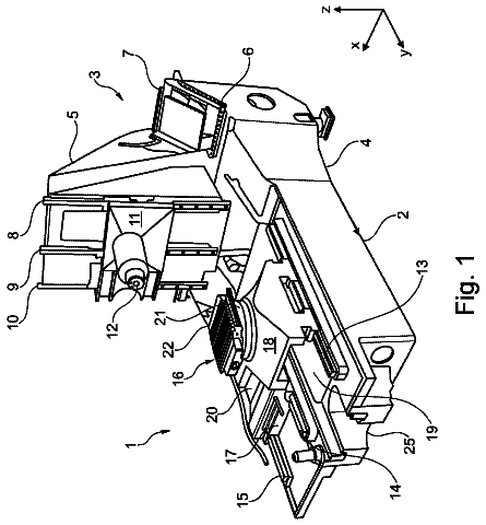
Universal machine tool including a chip collecting space

A machine tool comprising a machine column, a work spindle moveable in guides along the machine column in two coordinate axes by a motor and adapted to receive a cutting tool, a machine bed arranged on the front end of…

Filed2013
LapsedMay 2026
OwnerDECKEL MAHO Pfronten GmbH
Drawing from US 8,714,608 B2Lapsed, fee not paid5 drawings
Robotics & Automation · US 8,714,608 B2

Pin-type gripper

A pin-type gripper adapted for holding and transferring a target made of soft material.

Filed2011
LapsedMay 2026
OwnerKorea Pneumatic System Co., Ltd.
Drawing from US 8,717,167 B2Lapsed, fee not paid19 drawings
Robotics & Automation · US 8,717,167 B2

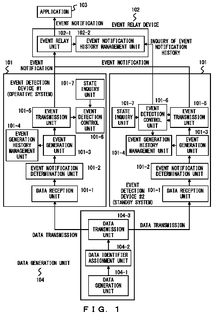
Event detection control method and system

The event message is transmitted from an operative event detection device to the application, the transmission history is held by a device different from the operative event detection device, an event identifier of an…

Filed2010
LapsedMay 2026
OwnerFujitsu Limited
Drawing from US 8,718,821 B2Lapsed, fee not paid10 drawings
Robotics & Automation · US 8,718,821 B2

Navigational control system for a robotic device

A navigational control system for altering movement activity of a robotic device operating in a defined working area, comprising a transmitting subsystem integrated in combination with the robotic device, the…

Filed2002
LapsedMay 2026
OwneriRobot Corporation