 Lapsed, fee not paid5 drawings
Industrial Equipment · US 8,713,949 B2
Ice level and quality sensing system employing digital imaging
A refrigerator includes a sensing system for detecting a level and quality of ice cubes in an ice cube storage bin.
US 8,713,951 B2 · Assignee: Mitsubishi Electric Corporation · Inventors: Takayama; Keisuke et al.
Sheet 1 of 8 from the published document. All sheets in the USPTO PDF
There are provided a plurality of use-side heat exchangers, inter-heat-medium heat exchangers, heat medium flow path switching devices, which switch flow paths, and pumps, which feed heat media to these paths; the inter-heat-medium heat exchangers heat or cool a heat medium by exchanging heat between the heat medium and a heat source fluid fed from a heat source apparatus. About half of the plurality of use-side heat exchangers are preheated or precooled, and the remaining use-side heat exchangers which are not preheated or precooled exchange heat media with use-side heat exchangers that have been preheated or precooled and that are not yet started to operate, suppressing energy consumed for preheating or precooling.
Some air conditioning apparatus of the prior art use heat media (cold liquid and hot liquid) from a heat source apparatus (heat source facility) for heat exchange precools or preheats a heat medium circulated between a heat source unit and an indoor unit (air conditioning unit). An exemplary disclosed air conditioning apparatus activates a heat source apparatus at a time of day calculated on the basis of various types of data including the temperature of a liquid, measured at night, the liquid being included in a pipe connecting a heat source unit and air conditioning unit, after which the air conditioning apparatus fully opens a valve of an indoor unit scheduled to be operated on that day in a forcible manner, and precools or preheats the indoor unit before the indoor unit is actually used (see Patent Literature 1, for example).
1 of 8 drawing sheets so far from the published document, cropped to the drawing. Every sheet is in the USPTO PDF.
What the patent claimed, word for word. All of it is now free to use.
The present invention relates to an air conditioning apparatus such as a multi-system air conditioner for a building.
Some air conditioning apparatus of the prior art use heat media (cold liquid and hot liquid) from a heat source apparatus (heat source facility) for heat exchange precools or preheats a heat medium circulated between a heat source unit and an indoor unit (air conditioning unit). An exemplary disclosed air conditioning apparatus activates a heat source apparatus at a time of day calculated on the basis of various types of data including the temperature of a liquid, measured at night, the liquid being included in a pipe connecting a heat source unit and air conditioning unit, after which the air conditioning apparatus fully opens a valve of an indoor unit scheduled to be operated on that day in a forcible manner, and precools or preheats the indoor unit before the indoor unit is actually used (see Patent Literature 1, for example).
Patent Literature
Patent Literature 1: Japanese Unexamined Patent Application Publication No. 2000-227242 (Abstract, FIG. 1)
Technical Problem
If many indoor units are scheduled to operate or an indoor unit scheduled to operate did not operate, a preheated (or precooled) heat medium is cooled (or heated) by natural heat dissipation (or heat absorption), wasting energy. Furthermore, if an attempt is made to achieve simultaneous operation of cooling and heating in which both an indoor unit operation for performing cooling operation and an indoor unit operation for performing heating operation are present, the indoor unit for heating may be precooled or the indoor unit for cooling may be preheated. Then, the outlet air temperature at the start of heating becomes low or the outlet air temperature at the start of cooling becomes high; the user thereby may lose comfort.
The present invention addresses the above problem and an object thereof is to obtain an air conditioning apparatus that can achieve simultaneous operation of heating and cooling by heating or cooling a heat medium with a heat source apparatus and allowing the heated or cooled heat source to pass through indoor units in such a way that preheating or precooling can be performed without energy being wasted.
Solution to Problem
An air conditioning apparatus according to the present invention includes a plurality of use-side heat exchangers, an inter-heat-medium heat exchanger that exchanges heat between a heat medium circulated in the use-side heat exchanger and a heat source fluid fed from a heat source apparatus, a heat medium feeding unit, temperature detecting means for detecting the temperature of the heat medium in a flow path that connects the inter-heat-medium heat exchanger and the use-side heat exchanger, temperature detecting means for detecting outside air temperature and a controller that controls the flow path of a heat medium. The controller, when the outside air temperature detected by the temperature detecting means is compared with a predetermined temperature at a preset preheating start time that is earlier than the estimated time that an indoor unit having the use-side heat exchanger starts operation and the outside air temperature is lower than the first predetermined temperature, preheats about half of the plurality of use-side heat exchangers by driving the heat medium feeding unit connected to a heat medium circulating circuit thereof to perform heat-up operation of the heat medium for the about half of the plurality of use-side heat exchangers and, when an operation for heating is commanded and a use-side heat exchanger which is commanded is not yet preheated, exchanges heat media between the commanded use-side heat exchanger and a use-side heat exchanger that has been preheated. The controller , when the outside air temperature detected by the temperature detecting means is compared with a second predetermined temperature at a preset precooling start time that is earlier than the estimated time that an indoor unit having the use-side heat exchanger starts operation and the outside air temperature is higher than the second predetermined temperature, precools about half of the plurality of use-side heat exchangers by driving the heat medium feeding unit connected to the heat medium circulating circuit to perform cool-down operation of the heat medium of the about half of the plurality of use-side heat exchangers and, when an operation for cooling is commanded and a use-side heat exchanger which is commanded is not yet precooled, exchanges heat media between the commanded use-side heat exchanger and a use-side heat exchanger that has been precooled.
Advantageous Effects of Invention
In the present invention, about half of a plurality of use-side heat exchangers are preheated or precooled, so an air conditioning apparatus that consumes less energy for preheating or precooling can be obtained.
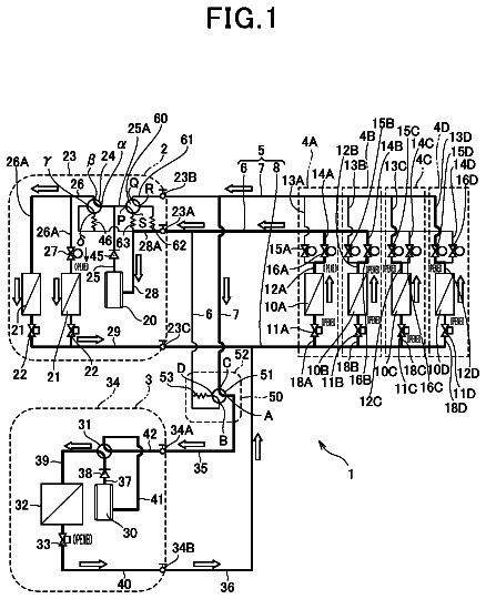
FIG. 1 is a system circuit diagram of an air conditioning apparatus according to Embodiment 1 of the present invention.
FIG. 2 is a system circuit diagram when the air conditioning apparatus according to Embodiment 1 of the present invention performs preheating.
FIG. 3 is a flowchart illustrating an exemplary method of preheating by the air conditioning apparatus according to Embodiment 1 of the present invention.
FIG. 4 is a system circuit diagram when heat media are exchanged between use-side heat exchangers of the air conditioning apparatus according to Embodiment 1 of the present invention.
FIG. 5 is a flowchart illustrating an exemplary method of exchanging heat media between use-side heat exchangers of the air conditioning apparatus according to Embodiment 1 of the present invention.
FIG. 6 is a flowchart illustrating an exemplary method of re-preheating by the air conditioning apparatus according to Embodiment 1 of the present invention.
FIG. 7 is a system circuit diagram showing a refrigerant-side circuit of an air conditioning apparatus according to Embodiment 2 of the present invention.
FIG. 8 is a system circuit diagram showing a refrigerant-side circuit of an air conditioning apparatus according to Embodiment 3 of the present invention.
FIG. 9 is a system circuit diagram showing another embodiment of a heat medium flow rate adjusting device.
Embodiment 1
FIG. 1 is a system circuit diagram of an air conditioning apparatus according to Embodiment 1 of the present invention. In the air conditioning apparatus according to Embodiment 1, a refrigerating cycle circuit is formed by connecting a compressor 10, a four-way valve 11, which is a refrigerant flow path switching device, a heat source-side heat exchanger 12, inter-heat-medium heat exchangers 14a and 14b, expansion devices 15a and 15b, such as electronic expansion valves, and an accumulator 16 with piping. A refrigerant circulates in the refrigerating cycle circuit. The inter-heat-medium heat exchanger 14a is equivalent to a first inter-heat-medium heat exchanger. The inter-heat-medium heat exchanger 14b is equivalent to a second inter-heat-medium heat exchanger. The expansion device 15a and expansion device 15b are respectively equivalent to a first expansion device and a second expansion device.
A heat medium circulating circuit, in which a heat medium circulates, is formed between a heat medium converter 3 and use-side heat exchangers 30a, 30b, 30c, and 30d. The refrigerant circulating in the refrigerating cycle circuit and the heat medium circulating in the heat medium circulating circuit are subjected to heat exchange in the heat medium converter 3.
The heat medium circulating circuit is formed by connecting the inter-heat-medium heat exchangers 14a and 14b, the use-side heat exchangers 30a, 30b, 30c, and 30d, pumps 31a and 31b, which are heat medium feeding units, heat medium flow path switching devices 32a, 32b, 32c, 32d, 33a, 33b, 33c, and 33d, and heat medium flow rate adjusting devices 34a, 34b, 34c, and 34d with piping. The pump 31a is equivalent to a first heat medium feeding unit. The pump 31b is equivalent to a second heat medium feeding unit. The heat medium flow path switching devices 32a, 32b, 32c, and 32d are equivalent to first heat medium flow path switching devices. The heat medium flow path switching devices 33a, 33b, 33c, and 33d are equivalent to second heat medium flow path switching devices. The heat medium flow rate adjusting devices 34a, 34b, 34c, and 34d are equivalent to heat medium flow rate adjusting parts. Although, in Embodiment 1, the number of indoor units 2 (use-side heat exchangers 30) is four (indoor units 2a, 2b, 2c, and 2d), this is not a limitation; any number of indoor units 2 (use-side heat exchangers 30) may be used.
In Embodiment 1, the compressor 10, the four-way valve 11, the heat source-side heat exchanger 12, the accumulator 16, and outside air temperature detecting means 37 are included in a heat source unit 1 (outdoor unit). A controller 50, which controls the entire air conditioning apparatus, is also included in the heat source unit 1. The use-side heat exchangers 30a, 30b, 30c, and 30d are respectively included in the indoor units 2a, 2b, 2c, and 2d. The inter-heat-medium heat exchangers 14a and 14b and the expansion devices 15a and 15b are included in the heat medium converter 3 (branching unit), which also functions as a heat medium branching unit. The heat medium flow path switching devices 32a, 32b, 32c, 32d, 33a, 33b, 33c, and 33d, the heat medium flow rate adjusting devices 34a, 34b, 34c, and 34d, and heat medium temperature detecting means 35a, 35b, 35c, 35d, 36a, 36b, 36c, and 36d are also included in the heat medium converter 3.
The heat source unit 1 and the heat medium converter 3 are connected with refrigerant pipes 4. The heat medium converter 3 and each of the indoor units 2a, 2b, 2c, and 2d (each of the use-side heat exchangers 30a, 30b, 30c, and 30d) are connected with heat medium pipes 5, in which a safety heat medium such as water or an antifreeze liquid flows. That is, the heat medium converter 3 and each of the indoor units 2a, 2b, 2c, and 2d (each of the use-side heat exchangers 30a, 30b, 30c, and 30d) are connected by a single heat medium path.
The compressor 10 compresses a drawn refrigerant and discharges (supplies) the compressed refrigerant. The four-way valve 11, which functions as a flow path switching device, performs valve switching according to a operation mode related to cooling or heating, in response to a command from the controller 50, so that the circulating circuit of the refrigerant is switched. In Embodiment 1, the following four operation modes are provided, according to each of which, the circulating circuit of the refrigerant is switched.
1. Cooling only operation (operation in which all indoor units 2 in operation are performing cooling (including dehumidification; this also applies to the following description))
2. Cooling-main operation (operation in which cooling is dominant when indoor units 2 that are performing cooling and indoor units 2 that are performing heating are present at the same time)
3. Heating only operation (operation in which all indoor units 2 in operation are performing heating)
4. Cooling-main operation (operation in which heating is dominant when indoor units 2 that are performing cooling and indoor units 2 that are performing heating are present at the same time)
The heat source-side heat exchanger 12 has fins (not shown) to expand heat transfer areas between a heat transfer pipe, through which the refrigerant passes, and the refrigerant passing through the heat transfer pipe and between the heat transfer pipe and the outside air, for example; the heat source-side heat exchanger 12 exchanges heat between the refrigerant and the outside air. In heating only operation or heating-main operation, for example, the heat source-side heat exchanger 12 functions as an evaporator to evaporate the refrigerant for gasification (vaporization). In cooling only operation or cooling-main operation, the heat source-side heat exchanger 12 functions as a condenser or gas cooler (the term condenser will be used in the following description). In some cases, the refrigerant may be placed in a state in which two phases of a gas and a liquid are mixed (gas-liquid two-phase refrigerant) without being completely gasified or liquefied.
The inter-heat-medium heat exchangers 14a and 14b each have a heat transfer part, through which the refrigerant passes, and a heat transfer part, through which the heat medium passes, so that heat is exchanged between the refrigerant and heat medium. In Embodiment 1, the inter-heat-medium heat exchanger 14a functions as an evaporator in cooling only operation and heating-main operation and also functions as a condenser in heating only operation and cooling-main operation. The inter-heat-medium heat exchanger 14a functions as an evaporator in cooling only operation and cooling-main operation to cool the heat medium by having the refrigerant absorb the refrigerant. In heating only operation and heating-main operation, the inter-heat-medium heat exchanger 14a functions as a condenser to heat the heat medium by having the refrigerant dissipate heat. For example, the expansion devices 15a and 15b, such as electronic expansion valves, reduce the pressure of the refrigerant by adjusting the refrigerant flow rate. The accumulator 16 has a function of storing an excess refrigerant present in the refrigerating cycle circuit and preventing much refrigerant liquid from returning to the compressor 10, which would otherwise damage the compressor 10.
The pumps 31a and 31b, which are heat medium feeding units, pressurize the heat medium to circulate it. An amount by which the heat medium is fed (an amount of discharge) by the pumps 31a and 31b can be changed by changing the rotation speed of built-in motors (not shown) within a fixed range. The use-side heat exchangers 30a, 30b, 30c, and 30d heat or cool the air in air conditioning space by, in their respective indoor units 2a, 2b, 2c, and 2d, exchanging heat between the heat medium and the air in the air conditioning space.
The heat medium flow path switching devices 32a, 32b, 32c, and 32d, which are three-way switching valves or the like, for example, are respectively connected with piping to the heat medium inlets of the use-side heat exchangers 30a, 30b, 30c, and 30d, and the flow paths are switched on the inlet side of the use-side heat exchangers 30a, 30b, 30c, and 30d (on the heat medium inlet side). The heat medium flow path switching devices 33a, 33b, 33c, and 33d, which are three-way switching valves or the like, for example, are respectively connected with piping to the heat medium outlets of the use-side heat exchangers 30a, 30b, 30c, and 30d, and the flow paths are switched on the outlet side of the use-side heat exchangers 30a, 30b, 30c, and 30d (on the heat medium output side). These switching devices perform switching to circulate, in the use-side heat exchangers 30a, 30b, 30c, and 30d, one of the heat media that have been heated or cooled in the inter-heat-medium heat exchangers 14a and 14b.
Furthermore, the heat medium flow rate adjusting devices 34a, 34b, 34c, and 34d, which are two-way flow rate adjusting valves, respectively adjust the flow rates of the heat medium entering the use-side heat exchangers 30a, 30b, 30c, and 30d.
<Operation Modes>
Next, the operation of the air conditioning apparatus in each operation mode will be described on the basis of the flows of the refrigerant and heat medium. The level of the pressure in the refrigerating cycle circuit and the like is not determined by a relationship with the reference pressure, but is represented as a relative pressure developed due to compression performed by the compressor 10, refrigerant flow rate control performed by, for example, the expansion devices 15a and 15b, or the like. This is also true for the level of temperature.
(Cooling Only Operation)
First, the refrigerant flow in the refrigerating cycle circuit will be described. In the heat source unit 1, the refrigerant sucked in by the compressor 10 is compressed and is discharged as a high-pressure gas refrigerant. The refrigerant discharged from the compressor 10 passes through the four-way valve 11 and enters the heat source-side heat exchanger 12, which functions as a condenser. While passing through the heat source-side heat exchanger 12, the high-pressure gas refrigerant is subjected to heat exchange with the outside air and condenses, after which the refrigerant exits as a high-pressure liquid refrigerant, passes through the refrigerant pipe 4, and enters the heat medium converter 3.
When the opening-degree of the expansion device 15a is adjusted, the refrigerant that has entered the heat-medium converter 3 is expanded and enters the inter-heat-medium heat exchanger 14a as a gas-liquid two-phase refrigerant at low temperature and low pressure. Since the inter-heat-medium heat exchanger 14a functions as an evaporator for the refrigerant, the refrigerant passing through the inter-heat-medium heat exchanger 14a cools the heat medium that is a target to be subjected to heat exchange (absorbs heat from the heat medium). That is, the refrigerant passing through the inter-heat-medium heat exchanger 14a cools the heat medium circulating in the heat medium circulating circuit. The refrigerant is not completely vaporized in the inter-heat-medium heat exchanger 14a, and exits still as the gas-liquid two-phase refrigerant. At that time, the expansion device 15b is left fully open to prevent a pressure loss.
The gas-liquid two-phase refrigerant at low temperature and low pressure further enters the inter-heat-medium heat exchanger 14b. The inter-heat-medium heat exchanger 14b also functions as an evaporator, so the refrigerant that has entered the inter-heat-medium heat exchanger 14b cools the heat medium, as described above, and exits as a gas refrigerant. The gas refrigerant that has exited the inter-heat-medium heat exchanger 14b passes through the refrigerant pipe 4, exits the heat medium converter 3, and enters the heat source unit 1.
The refrigerant that has entered the heat source unit 1 passes through the four-way valve 11 and accumulator 16, and is then sucked into the compressor 10 again.
Next, the heat medium flow in the heat medium circulating circuit will be described. The heat medium is subjected to heat exchange with the refrigerant in the inter-heat-medium heat exchangers 14a and 14b and is cooled. The heat medium cooled in the inter-heat-medium heat exchanger 14a is sucked in by the pump 31a and fed to a first heat medium feeding pipe 61a. The heat medium cooled in the inter-heat-medium heat exchanger 14b is sucked in by the pump 31b and fed to a second heat medium feeding pipe 61b.
The flow paths of the heat media in the first heat medium flow path 61a and second heat medium flow path 61b are switched by the heat medium flow path switching devices 32a, 32b, 32c, and 32d, and the heating media enter the use-side heat exchangers 30a, 30b, 30c, and 30d. In this case, the flow paths are switched so that the cooling only capacity of the indoor units cooled by the heat medium in the first heat medium feeding pipe 61a and the cooling only capacity of the indoor units cooled by the heat medium in the second heat medium feeding pipe 61b each account for about half of the cooling only capacity of all the indoor units. The cooling capacities of the indoor units 2a, 2b, 2c, and 2d can be determined by, for example, the controller 50, and the flow paths of the heat medium flow path switching devices 32a, 32b, 32c, and 32d are switched on the basis of the cooling capacities. Here, the heat medium flow path switching devices 32a, 32b, 32c, and 32d are switched so that the heat medium in the first heat medium feeding pipe 61a enters the use-side heat exchangers 30a and 30b and the heat medium in the second heat medium feeding pipe 61b enters the use-side heat exchangers 30c and 30d, for example.
The flow rates of the heat media that have passed through the heat medium flow path switching devices 32a, 32b, 32c, and 32d are adjusted by the heat medium flow rate adjusting devices 34a, 34b, 34c, and 34d, after which they enter their corresponding use-side heat exchangers 30a, 30b, 30c, and 30d. To stop any one of the indoor units 2 (2a, 2b, 2c, and 2d), the heat medium flow rate adjusting device 34 (34a, 34b, 34c, or 34d) corresponding to the indoor unit 2 to be stopped is fully closed. The heat media that have passed through the use-side heat exchangers 30a, 30b, 30c, and 30d then pass through the heat medium flow path switching devices 33a, 33b, 33c, and 33d. In this case, the heat medium flow path switching devices 33a, 33b, 33c, and 33d are switched so that the heat medium that has exited the first heat medium feeding pipe 61a returns to the first heat medium return pipe 62a. Similarly, the heat medium flow path switching devices 33a, 33b, 330, and 33d are switched so that the heat medium that has exited the second heat medium feeding pipe 61b returns to the second heat medium return pipe 62b.
(Heating Only Operation)
First, the refrigerant flow in the refrigerating cycle circuit will be described. In the heat source unit 1, the refrigerant sucked in by the compressor 10 is compressed and is discharged as a high-pressure gas refrigerant. The refrigerant discharged from the compressor 10 passes through the four-way valve 11, further passes through the refrigerant pipe 4, and enters the heat medium converter 3.
The gas refrigerant that has entered the heat medium converter 3 enters the inter-heat-medium heat exchanger 14b. Since the inter-heat-medium heat exchanger 14b functions as a condenser for the refrigerant, the refrigerant passing through the inter-heat-medium heat exchanger 14b cools the heat medium that is a target to be subjected to heat exchange (dissipates heat to the heat medium). The refrigerant is not completely liquefied in the inter-heat-medium heat exchanger 14b and exits as a gas-liquid two-phase refrigerant at high temperature and high pressure.
The gas-liquid two-phase refrigerant at high temperature and high pressure further enters the inter-heat-medium heat exchanger 14a. At that time, the expansion device 15b is left fully open to prevent a pressure loss. The refrigerant that has entered the inter-heat-medium heat exchanger 14a heats the heat medium as described above and exits the inter-heat-medium heat exchanger 14a as a liquid refrigerant. The pressure of the liquid refrigerant that has exited is reduced by the expansion device 15a, and the refrigerant becomes a gas-liquid two-phase refrigerant at low temperature and low pressure. The gas-liquid two-phase refrigerant at low temperature and low pressure passes through the refrigerant pipe 4, exits the heat medium converter 3, and enters the heat source unit 1.
The refrigerant that has entered the heat source unit 1 enters the heat source-side heat exchanger 12, evaporates by being subjected to heat exchange with the air, and exits as a gas refrigerant or gas-liquid two-phase refrigerant. The refrigerant that has been subjected to evaporation passes through the four-way valve 11 and accumulator 16, and is then sucked into the compressor 10 again.
Next, the heat medium flow in the heat medium circulating circuit will be described. The heat media are subjected to heat exchange with the refrigerants in the inter-heat-medium heat exchangers 14a and 14b and are heated. The heat medium heated in the inter-heat-medium heat exchanger 14a is sucked in by the pump 31a and fed to the first heat medium feeding pipe 61a. The heat medium heated in the inter-heat-medium heat exchanger 14b is sucked in by the pump 31b and fed to the second heat medium feeding pipe 61b.
The flow paths of the heat media in the first heat medium feeding pipe 61a and second heat medium feeding pipe 61b are switched by the heat medium flow path switching devices 32a, 32b, 32c, and 32d, and the heating media enter the use-side heat exchangers 30a, 30b, 30c, and 30d. In this case, the flow paths are switched so that the heating only capacity of the indoor units heated by the heat medium in the first heat medium feeding pipe 61a and the heating only capacity of the indoor units heated by the heat medium in the second heat medium feeding pipe 61b each account for about half of the heating only capacity of all the indoor units 2a, 2b, 2c, and 2d. The heating capacity of the indoor units 2a, 2b, 2c, and 2d can be determined by, for example, the controller 50, and the flow paths of the heat medium flow path switching devices 32a, 32b, 32c, and 32d are switched on the basis of the cooling capacities. Here, the heat medium flow path switching devices 32a, 32b, 32c, and 32d are switched so that the heat medium in the first heat medium feeding pipe 61a enters the use-side heat exchangers 30a and 30b and the heat medium in the second heat medium feeding pipe 61 b enters the use-side heat exchangers 30c and 30d, for example.
The flow rates at which the heat media that have passed through the heat medium flow path switching devices 32a, 32b, 32c, and 32d enter their corresponding use-side heat exchangers 30a, 30b, 30c, and 30d are adjusted by the heat medium flow rate adjusting devices 34a, 34b, 34c, and 34d. To stop any one of the indoor units 2, the pertinent heat medium flow rate adjusting device 34 is fully closed. The heat media then pass through the heat medium flow path switching devices 33a, 33b, 33c, and 33d. In this case, the heat medium flow path switching devices 33a, 33b, 33c, and 33d are switched so that the heat medium that has exited the first heat medium feeding pipe 61 a returns to the first heat medium return pipe 62a and the heat medium that has exited the second heat medium feeding pipe 61b returns to the second heat medium return pipe 62b.
(Cooling-Main operation)
The refrigerant flow in the refrigerating cycle circuit in cooling-main operation will be described below. First, a difference from cooling only operation will be outlined. In cooling only operation, the expansion device 15a has functioned as an expansion valve and the expansion device 15b has been fully opened; in cooling-main operation, conversely, the expansion device 15a is fully opened and the expansion device 15b functions as an expansion valve. Then, in cooling-main operation, the inter-heat-medium heat exchanger 14a functions as a condenser and the inter-heat-medium heat exchanger 14b functions as an evaporator; by comparison, in cooling only operation, both the inter-heat-medium heat exchangers 14a and 14b have functioned as an evaporator. Since one of the inter-heat-medium heat exchangers 14a and 14b functions as a condenser and the other functions as an evaporator in this way, simultaneous operation of cooling and heating can be achieved.
In the heat source unit 1, the refrigerant sucked in by the compressor 10 is compressed and is discharged as a high-pressure gas refrigerant. The refrigerant discharged from the compressor 10 passes through the four-way valve 11 and enters the heat source-side heat exchanger 12, which functions as a condenser. While passing through the heat source-side heat exchanger 12, the high-pressure gas refrigerant is subjected to heat exchange with the outside air and condenses. However, the refrigerant is not completely liquefied and exits as a gas-liquid two-phase refrigerant at high pressure, after which the refrigerant passes through the refrigerant pipe 4 and enters the heat medium converter 3.
The refrigerant that has entered the heat medium converter 3 enters the inter-heat-medium heat exchanger 14a. At that time, the expansion device 15a is left fully open to prevent a pressure loss. Although, in cooling only operation, the inter-heat-medium heat exchanger 14a has functioned as an evaporator for the refrigerant, it functions as a condenser for the refrigerant in cooling-main operation. Therefore, the refrigerant passing through the inter-heat-medium heat exchanger 14a heats the heat medium that is a target to be subjected to heat exchange, and is liquefied (dissipates heat to the heat medium).
The pressure of the liquefied refrigerant is reduced by the expansion device 15b, and the refrigerant becomes a gas-liquid two-phase refrigerant at low temperature and low pressure. The refrigerant at low temperature and low pressure enters the inter-heat-medium heat exchanger 14b. Since the inter-heat-medium heat exchanger 14b functions as an evaporator for the refrigerant, the refrigerant passing through the inter-heat-medium heat exchanger 14b cools the heat medium that is a target to be subjected to heat exchange (absorbs heat from the heat medium). The refrigerant that has exited passes through the refrigerant pipe 4, exits the heat medium converter 3, and enters the heat source unit 1.
The refrigerant that has entered the heat source unit 1 passes through the four-way valve 11 and accumulator 16, and is then sucked into the compressor 10 again.
Next, the heat medium flow in the heat medium circulating circuit will be described. The heat medium is subjected to heat exchange with the refrigerant in the inter-heat-medium heat exchanger 14a and is heated. The heat medium heated in the inter-heat-medium heat exchanger 14a is sucked in by the pump 31a and fed to the first heat medium feeding pipe 61a. In the inter-heat-medium heat exchanger 14b, the heat medium is subjected to heat exchange with the refrigerant and is cooled. The heat medium cooled in the inter-heat-medium heat exchanger 14b is sucked in by the pump 31b and fed to the second heat medium flow path 61b.
The flow paths of the heat media in the first heat medium feeding pipe 61a and in the second heat medium feeding pipe 61b are switched by the heat medium flow path switching devices 32a, 32b, 32c, and 32d, and the heating media enter the use-side heat exchangers 30a, 30b, 30c, and 30d. In this case, the flow paths are switched depending on whether the indoor units 2a, 2b, 2c, and 2d are to perform cooling or heating operation. That is, in cooling-main operation, the heat medium is heated because the inter-heat-medium heat exchanger 14a functions as a condenser for the refrigerant. Accordingly, the flow paths are switched so that indoor units to be used for heating are connected to the same side as the inter-heat-medium heat exchanger 14a to form a heat medium circulating circuit between the indoor units for heating and the inter-heat-medium heat exchanger 14a. The inter-heat-medium heat exchanger 14b cools the heat medium because it functions as an evaporator for the refrigerant. Accordingly, the flow paths are switched so that indoor units to be used for cooling are connected to the same side as the inter-heat-medium heat exchanger 14 to form a heat medium circulating circuit between the indoor units for cooling and the inter-heat-medium heat exchanger 14b.
If, for example, the indoor units 2a, 2b, and 2c are in operation for cooling and the indoor unit 2d is in operation for heating, then the heat medium in the first heat medium feeding pipe 61b may pass through the heat medium flow path switching devices 32a, 32b, and 32c and the cooled heat medium may enter the use-side heat exchangers 30a, 30b, and 30c. The heat medium in the second heat medium feeding pipe 61a may pass through the heat medium flow path switching device 32d and the heated heat medium may enter the use-side heat exchanger 30d. Whether the indoor units 2a, 2b, 2c, and 2d are in operation for cooling or heating can be decided by, for example, the controller 50, and the flow paths of the heat medium flow path switching devices 32a, 32b, 32c, and 32d are switched accordingly.
The flow rates at which the heat media that have passed through the heat medium flow path switching devices 32a, 32b, 32c, and 32d enter their corresponding use-side heat exchangers 30a, 30b, 30c, and 30d are adjusted by the heat medium flow rate adjusting devices 34a, 34b, 34c, and 34d. To stop any one of the indoor units 2, the pertinent heat medium flow rate adjusting device 34 is fully closed. The heat media then pass through the heat medium flow path switching devices 33a, 33b, 33c, and 33d. in this case, the heat medium flow path switching devices 33a, 33b, 33c, and 33d are switched so that the heat medium that has exited the first heat medium feeding pipe 61a returns to the first heat medium return pipe 62a. Similarly, the heat medium flow path switching devices 33a, 33b, 33c, and 33d are switched so that the heat medium that has exited the second heat medium feeding pipe 61b returns to the second heat medium return pipe 62b.
(Heating-Main Operation)
The refrigerant flow in the refrigerating cycle circuit in heating-main operation will be described below. First, a difference from heating only operation will be outlined. In heating only operation, the expansion device 15a has functioned as an expansion valve and the expansion device 15b has been fully opened; in heating-main operation, conversely, the expansion device 15a is fully opened and the expansion device 15b functions as an expansion valve. Then, in heating-main operation, the inter-heat-medium heat exchanger 14a functions as an evaporator and the inter-heat-medium heat exchanger 14b functions as a condenser; by comparison, in heating only operation, both the inter-heat-medium heat exchangers 14a and 14b have functioned as a condenser.
In the heat source unit 1, the refrigerant sucked in by the compressor 10 is compressed and is discharged as a high-pressure gas refrigerant. The refrigerant discharged from the compressor 10 passes through the four-way valve 11, further passes through the refrigerant pipe 4, and enters the heat medium converter 3.
The gas refrigerant that has entered the heat medium converter 3 enters the inter-heat-medium heat exchanger 14b. Since the inter-heat-medium heat exchanger 14b functions as a condenser for the refrigerant, the refrigerant passing through the inter-heat-medium exchanger 14b heats the heat medium that is a target to be subjected to heat exchange, and is liquefied (dissipates heat to the heat medium).
The high-pressure liquid refrigerant is made to be a gas-liquid two-phase refrigerant at low temperature and low pressure by the expansion device 15b, and then enters the inter-heat-medium heat exchanger 14a. Since the inter-heat-medium heat exchanger 14a functions as an evaporator for the refrigerant, the refrigerant passing through the inter-heat-medium heat exchanger 14a cools the heat medium that is a target to be subjected to heat exchange, and evaporates (absorbs heat from the heat medium). At that time, the expansion device 15a is left fully open to prevent a pressure loss. The gas refrigerant or gas-liquid two-phase refrigerant that has exited passes through the refrigerant pipe 4, exits the heat medium converter 3, and enters the heat source unit 1.
The refrigerant that has entered the heat source unit 1 enters the heat source-side heat exchanger 12 in which the refrigerant is subjected to heat exchange with the air and evaporates, after which the refrigerant exits as a gas refrigerant or gas-liquid two-phase refrigerant. The refrigerant that has evaporated passes through the four-way valve 11 and accumulator 16, and is then sucked into the compressor 10 again.
Next, the heat medium flow in the heat medium circulating circuit will be described. The heat medium is subjected to heat exchange with the refrigerant in the inter-heat-medium heat exchanger 14a and is cooled. The heat medium cooled in the inter-heat-medium heat exchanger 14a is sucked in by the pump 31a and fed to the first heat medium feeding pipe 61a. In the inter-heat-medium heat exchanger 14b, the heat medium is subjected to heat exchange with the refrigerant and is heated. The heat medium heated in the inter-heat-medium heat exchanger 14b is sucked in by the pump 31b and fed to the second heat medium flow path 61b.
The heat medium flow path switching devices 32 and 33 and the heat medium flow rate adjusting devices 34 work as in cooling-main operation described above,
As described above for cooling-main operation and heating-main operation, the air conditioning apparatus in this embodiment enables simultaneous operation of cooling and heating by having one of the inter-heat-medium heat exchangers 14a and 14b function as a condenser and having the other function as an evaporator.
<Heat Medium Preheating Method>
Next, preheating will be described, which is performed to prevent the outlet air temperature from being lowered when heating is started in a state in which some indoor units 2 are stopping.
As described above, the heat source unit 1 according to Embodiment 1 circulates heat media between the heat medium converter 3 and use-side heat exchangers 30. As for a multi-system air conditioner intended for a building, some heat medium pipes 5, which connect the heat medium converter 3 and use-side heat exchangers, may be, for example, measure about 50 meters long in one way, so a large amount of heat medium is staying. While the air conditioning apparatus is stopping at night in winter, for example, the heat media staying in the heat medium pipes 5 and use-side heat exchangers 30 dissipate heat. Accordingly, it takes time for the indoor units 2 to start heating, and the outlet air temperature at the start of heating is lowered; the user thereby will lose comfort.
Preheating of the heat medium may be carried out before the indoor units 2 start heating. If all the heat medium pipes 5 and all the use-side heat exchangers 30 are preheated, however, energy required for the preheating becomes too much. Alternatively, preheated indoor units 2 may not be operated on that day or may be intended for cooling, further wasting energy.
In view of the above situation, the air conditioning apparatus according to Embodiment 1 suppresses a drop of the outlet air temperature when some indoor units 2 start heating, by a method described below. Specifically, when the outside air temperature is lower than a certain temperature in winter, about half of all the indoor units 2 are operated for heating before heating starts. Then, about half of all the heat medium pipes 5 can be preheated, suppressing a drop of the temperature of the outlet air from the indoor units 2.
FIG. 2 is a circuit diagram illustrating an example of preheating operation of Embodiment 1. Half of all the use-side heat exchangers 30 (indoor units 2) are selected in advance that performs preheating operation, having a longer heat medium pipe 5 in order. This is because the length of the heat medium pipe 5 varies depending on the place where the indoor unit 2 is installed and the longer heat medium pipe 5 can store much more preheated heat medium. If an odd number of use-side heat exchangers, five use-side heat exchangers for example, are connected to the air conditioning apparatus, three use-side heat exchangers perform preheating operation. Information on which use-side heat exchanger (indoor units 2) is selected is stored in the controller 50.
FIG. 3 is a flowchart illustrating an exemplary method of preheating in Embodiment 1 of the present invention. In the following description, the use-side heat exchangers 30a and 30b are used for preheating.
The description continues in the full USPTO document.
About 6,449 words. The USPTO PDF has it with every drawing.
Fees are due 3.5, 7.5 and 11.5 years after grant. This patent expired on May 6, 2026, so the fee marked "not paid" was the one that went unpaid.
AIR CONDITIONING APPARATUS
Filed May 2009 · published Feb 2012Air conditioning apparatus
Filed May 2009 · granted May 2014Earlier publications, parents and continuations. None of them can still be enforced, or this patent would not be listed.
Prior art cited by the examiner or applicant. Useful when you check your own idea for novelty.
Everything on this page comes from the documents linked above.