Technical field
The present invention relates to a storage system comprising multiple microprocessors and a method for sharing the processing in this storage system.
Background art
A storage system ordinarily includes multiple storage devices and a controller, which receives an I/O (Input/Output) request from an external device (for example, a host computer). The configuration of the controller, for example, is disclosed in Patent Literature 1.
Citation list
Patent Literature
[ptl 1]
Japanese Patent Application Laid-Open No. 2005-044010
Summary of invention
Technical Problem
In a case where the I/O request received from the external device is a read request, the controller, for example, executes processing (a storage device read process) that transfers data from the storage device to a cache memory (CM), and processing (a CM read process) that reads the data from the CM and transfers this data to the external device, or only the CM read process.
In a case where the I/O request received from the external device is a write request, the controller, for example, executes processing (a CM write process) that transfers data received from the external device to the CM, and processing (a storage device write process) that transfers the data from the CM to the storage device.
Multiple microprocessors of the controller are able to execute synchronous processing and asynchronous processing. "Synchronous processing" must be executed between the time when an I/O request is received from the external device and the time when a response to this I/O request is returned to the external device. Synchronous processing, for example, includes the execution of the above-mentioned storage device read process, the CM read process, and the CM write process. Alternatively, "asynchronous processing" signifies processing other than synchronous processing, and, for example, refers to the execution of the above-mentioned storage device write process.
In a case where the microprocessors execute asynchronous processing for a long time, the execution of the synchronous processing will be delayed to that extent, and therefore the response to the external device will be delayed. By contrast, in a case where synchronous processing is given priority, the response to the external device can be speeded up. However, since the asynchronous processing will be delayed in accordance with this, data that has not been written to the storage device accumulates in large amounts in the CM, reducing the CM free space. When CM free space is reduced, it is not possible to secure enough cache area for processing an I/O request from the external device, making it necessary to wait for the CM free space to increase in accordance with a storage device write process, and thereby corrupting the synchronous processing response.
Accordingly, an object of the present invention is to provide a storage system, which comprises multiple microprocessors, and which is able to make efficient use of each microprocessor by appropriately executing both synchronous processing and asynchronous processing in each microprocessor, and a method for sharing processing in this storage system. Other objects of the present invention should become clear from the description of the embodiment, which will be explained below.
Solution to Problem
In a storage system of the present invention that solves for the problems described above, the microprocessor of the controller is able to execute synchronous processing up to a preset upper limit value, and asynchronous processing may be executed in a case where synchronous processing is not executed.
Brief description of drawings
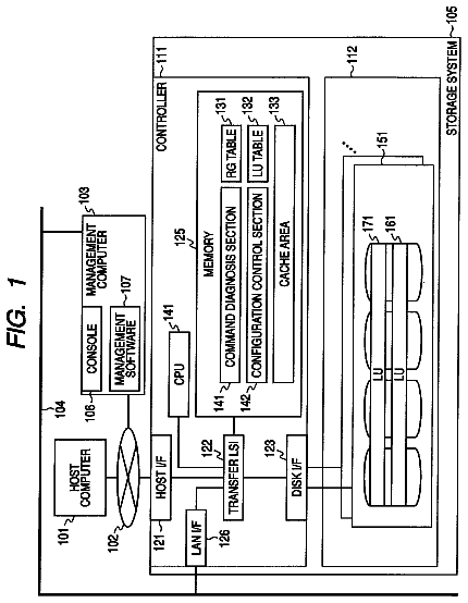
FIG. 1 is a diagram of a computer system that comprises a storage system.
FIG. 2 is a block diagram of various types of information that are used by each microprocessor.
FIG. 3 is a block diagram of a management console.
FIG. 4 is a table for managing the microprocessor rate of operation.
FIG. 5 is a table for managing a cache dirty ratio.
FIG. 6 is a table for tuning the upper limit value of the execution count for each mode.
FIG. 7 is a table for managing the execution count for synchronous processing and asynchronous processing.
FIG. 8 is a table for managing a process that is executed cyclically.
FIG. 9 is a table for managing a threshold for resetting the upper limit value of the execution count for synchronous processing and asynchronous processing.
FIG. 10 is a table for managing synchronous processing.
FIG. 11 is a table for managing asynchronous processing.
FIG. 12 is a flowchart showing overall processing.
FIG. 13 is a flowchart showing host interface processing.
FIG. 14 is a flowchart showing disk interface processing.
FIG. 15 is a flowchart showing processing for reviewing the upper limit value of the execution count.
FIG. 16 is a flowchart of processing for reading read-requested host data from the cache memory.
FIG. 17 is a flowchart of the continuation of the processing of FIG. 16.
FIG. 18 is a flowchart of the continuation of the processing of FIG. 17.
FIG. 19 is a flowchart showing the processing for writing write-requested host data to the cache memory.
FIG. 20 is a flowchart of the continuation of the processing of FIG. 19.
FIG. 21 is a flowchart of the continuation of the processing of FIG. 20.
FIG. 22 is a flowchart showing the processing for reading data from the storage device.
FIG. 23 is a flowchart of the continuation of the processing of FIG. 22.
FIG. 24 is a flowchart showing the processing for writing host data to the storage device.
FIG. 25 is a flowchart of the continuation of the processing of FIG. 24.
FIG. 26 is a flowchart showing the processing for setting either a limit or a threshold for an execution count from the management console.
FIG. 27 is an example of a management screen provided by the management console.
FIG. 28 is a block diagram of a table used in a storage system related to a second embodiment.
FIG. 29 is a block diagram of various types of information used by respective microprocessors of a storage system related to a third embodiment.
FIG. 30 is a table for managing information to be set in the microprocessor.
FIG. 31 is a flowchart of I/O processing.
FIG. 32 is a flowchart showing the processing by the microprocessor in charge of the host interface.
FIG. 33 is a flowchart showing the processing by the microprocessor in charge of the disk interface.
FIG. 34 is a flowchart showing the processing for switching the attribute of the microprocessor.
FIG. 35 is a diagram schematically showing the operating status of the microprocessor.
FIG. 36 is a table for managing information to be set in the microprocessor, which is used by a storage system related to a fourth embodiment.
FIG. 37 is a flowchart of I/O processing.
FIG. 38 is a flowchart of synchronous processing.
FIG. 39 is a flowchart of asynchronous processing.
FIG. 40 is a flowchart showing the processing for switching the attribute of the microprocessor.
FIG. 41 is an overall diagram of a computer system comprising a storage system related to a fifth embodiment.
FIG. 42 is a flowchart showing the processing for reading from the storage device host data that is operated on by a storage system related to a sixth embodiment.
Description of embodiments
The embodiments of the present invention will be explained below on the basis of the drawings. The present invention, as will be described hereinbelow, is related to a storage system that includes multiple storage devices that are able to provide multiple logical volumes, and a controller, which receives from an external device an input/output request that specifies any of the multiple logical volumes and processes this request. The controller includes at least one first interface for communicating with the external device, at least one second interface for communicating with the storage devices, a memory, which is respectively coupled to each first interface and each second interface, and multiple microprocessors, which are respectively coupled to each first interface, each second interface, and the memory. Each of the microprocessors is able to execute synchronous processing, whose execution is triggered by the input-output request from the external device, and asynchronous processing, which is processing other than synchronous processing. Each of the microprocessors is able to execute the synchronous processing up to a preset upper limit value, and is able to execute the asynchronous processing in a case where the synchronous processing is not executed.
Furthermore, the descriptions of the embodiments discussed below do not limit the scope of the present invention. Not all of the combinations of characteristic features explained in the embodiments are necessarily essential to the invention solution.
Embodiment 1
FIG. 1 shows a computer system comprising a storage system related to a first embodiment of the present invention. In the explanation that follows, interface may be shortened to "I/F".
The computer system comprises one or more host computers 180, a storage system 10, and a management console 20. Communication between the host computer 180 and the storage system 10, for example, is carried out via a communication network 190.
The communication network 190, for example, may be any network that is capable of carrying out data communications, such as a SAN (Storage Area Network), a LAN (Local Area Network), the Internet, a leased line, or a public line. The protocol for communications between the host computer 180 and the storage system 10, for example, may be an arbitrary protocol of various protocols that make it possible to send and receive data, such as either the fibre channel protocol or the TCP/IP protocol.
When the host computer 180 is a so-called mainframe, for example, a communication protocol such as FICON (Fibre Connection: registered trademark), ESCON (Enterprise System Connection: registered trademark), ACONARC (Advanced Connection Architecture: registered trademark), and FIBARC (Fibre Connection Architecture: registered trademark) may be used.
The management console 20 is a computer for managing the storage system 10, and is operated by a user.
The host computer 180 sends an I/O request to the storage system 10. The I/O request, for example, is either a read request or a write request. A read request, for example, comprises a LUN (Logical Unit Number) and a LBA (Logical Block Address) that correspond to the read-source of the read-targeted data. A write request, for example, comprises a LUN and a LBA that correspond to the write-destination of write-targeted data, and the write-targeted data. The LUN is allocated to a logical volume 171 in the storage system 10. The LBA is an address of a storage area (block) inside the logical volume 171.
In the following explanation, the read-targeted data may be called read data and the write-targeted data may be called write data. In addition, the read-targeted data and the write-targeted data may be called host data.
The storage system 10 comprises multiple HDDs (Hard Disk Drives) 170 and a controller 100. The controller 100 receives an I/O request from the host computer 180, accesses any storage device 170, and returns the processing result of the I/O request to the host computer 180.
The HDD 170 is one example of a storage device. The storage device is not limited to a hard disk drive. For example, a variety of devices that are capable of reading and writing data, such as a semiconductor memory device, an optical disk device, a magneto-optical disk device, a magnetic tape device, and a flexible disk device, may be used as the storage device.
Multiple logical volumes 171 may be created based on the physical storage area of the multiple HDDs 170. Specifically, a RAID (Redundant Array of Independent (or Inexpensive) Disks) group is created in accordance with two or more HDDs 170. Either one or multiple logical volumes 171 are set using the physical storage area of respective RAID groups. One logical volume 171 is shown in FIG. 1, but under ordinary circumstances, the storage system 10 comprises a large number of RAID groups and a large number of logical volumes 171.
A LUN is allocated to the logical volume 171, and this LUN is provided to the host computer 180. The controller 100 identifies a logical volume corresponding to a LUN specified by an I/O request, accesses the HDD 170 constituting the basis of this logical volume, and reads/writes data from/to this HDD 170.
In Thin Provisioning technology, the logical volume is a pool volume, and a LUN is not allocated thereto. In this case, the LUN is allocated to a logical volume that is set virtually. The controller 100, upon receiving an I/O request for the virtual logical volume, accesses the pool volume corresponding to the access destination in the virtual logical volume, and reads/writes data from/to this pool volume.
The controller 100, for example, comprises one or more FEPKs (Front-End PacKage) 110 that serve as one or more host I/F units, one or more MPPKs (MicroProcessor PacKage) 120 that serves as one or more controllers, one or more CMPKs (Cache Memory PacKage) 130 that serve as one or more shared memory units, and one or more BEPKs (Back-End PacKage) 140 that serve as one or more disk I/F units.
Each FEPK 110, each MPPK 120, each CMPK 130 and each BEPK 140 is coupled to an internal network 150. The internal network 150, for example, may be either a LAN or other such communication network, or a crossbar switch or other such switching device. Each MP (MicroProcessor) 121 of each MPPK 120 is communicably coupled to each FEPK 110, each CMPK 130, and each BEPK 140 via the internal network 150.
The FEPK 110 is an interface device for communicating with the host computer 180, and comprises a host I/F 111 and a transfer control circuit 112. Each host I/F 111, for example, is a communication port. The transfer control circuit 112 is for controlling the transfer of either an I/O request or data that was received by the host I/F 111.
The BEPK 140 is an interface device for communicating with the HDD 170, and comprises a disk I/F 141 and a transfer control circuit 142. The disk I/F 141, for example, is a communication port. The BEPK 140 is coupled to each HDD 170, and is also coupled to the internal network 150. The BEPK 140 mediates the passing of either read-targeted data or write-targeted data between the internal network 150 side and the HDD 170. The transfer control circuit 142 controls the transfer of data.
The CMPK 130 comprises a cache memory (hereinafter shortened to "CM") 131, and a control memory 132. The CM 131 and the control memory 132 may be configured from volatile memories, such as DRAM (Dynamic Random Access Memory).
The CM 131 temporarily stores data (write-targeted data) to be written to the HDD 170. The CM 131 also temporarily stores data (read-targeted data) that has been read from the HDD 170.
The control memory 132 stores various types of control information required for processing, such as synchronous processing and asynchronous processing. For example, HDD configuration information and volume management information may be cited as types of control information. HDD configuration information manages which RAID group is configured from which HDD 170. The volume management information manages which logical volume corresponds to what kind of function.
The MPPK 120 controls the operation of the storage system 10. The MPPK 120 comprises multiple MPs 121, a local memory (LM) 122, and a bus 123 for coupling each MP 121 to the LM 122.
In this embodiment, a case in which multiple MPPKs 120 comprise multiple MPs 121 is shown, but the present invention is not limited to this, and a configuration such that multiple MPPKs 120 comprise one MP 121 each may also be used.
Either all or a portion of the control information stored in the control memory 132 is copied to the LM 122. The portion of the control information is the part required for the MPPK 120 comprising the LM 122 that stores this portion of the control information.
FIG. 2 shows various types of information (tables, queues) that are stored in the LM 122 of the MPPK 120. The LM 122, for example, stores a MP rate of operation table 210, a cache dirty ratio table 220, an execution count limit tuning table 230, an execution count limit table 240, a cycle management table 250, a threshold table for setting a limit on the number of executions 260, a synchronous process table 270, an asynchronous process table 280, a host I/F synchronous processing queue 410, a disk I/F synchronous processing queue 420, and a disk I/F asynchronous processing queue 430. An MP rate of operation table 210 either exists for each MP in the MPPK, or there is only one such table 210 in the MPPK.
Each of the tables 210 through 270 will be explained below. The host I/F synchronous processing queue 410 is for managing a synchronous processing request related to the host I/F 111. Synchronous processing may include processing (a host data CM read process) for reading host computer 180-requested read-targeted data from the CM 131 and transferring this data to the host computer 180, and processing (a host data CM write process) for storing write-targeted data received from the host computer 180 and storing this data in the CM 131.
The disk I/F synchronous processing queue 420 is for managing a synchronous processing request related to the disk I/F 141. Synchronous processing related to the disk I/F 141, for example, may include processing (a host data HDD read process) for reading read-targeted data for which a read has been requested by the host computer 180 from the storage device 170 corresponding to the read-source logical volume 171.
The disk I/F asynchronous processing queue 430 is for managing an asynchronous processing request related to the disk I/F 141. Asynchronous processing related to the disk I/F 141, for example, may include processing (a host data HDD write process) for writing write-targeted data received from the host computer 180 to the storage device 170 corresponding to the write-destination logical volume 171.
Furthermore, although omitted from the drawing, one or more computer programs executed by the respective MPs 121 may be stored in the LM 122. Each MP 121 realizes a function shown in a flowchart, which will be described hereinbelow, by reading and executing a computer program. For example, the computer programs and operating systems corresponding to the respective flowcharts of FIGS. 12 through 26 may be stored in the LM 122.
Another table and another queue besides the tables and queues shown in FIG. 2 may also be stored in the LM 122. For example, a table for managing a remote copy and a queue for managing a processing request when a failure has occurred may also be stored in the LM 122.
FIG. 3 shows the configuration of the management console 20. The operating status of the storage system 10 can be checked via the management console 20. In addition, the setting values of the various types of tables can be changed via the management console 20. The management console 20, for example, is coupled by way of a bus 27 to a communication I/F 21, an input I/F 22, a display I/F 23, a memory 24, and HDD 25 and a CPU (Central Processing Unit) 26.
The memory 24, for example, comprises a ROM (Read Only Memory) and a RAM (Random Access Memory), and stores a boot program and programs for executing various types of processing. A work area for use by the CPU 26 may also be provided in the memory 24.
The HDD 25 stores a program and various types of information that need to be maintained even when the power to the management console 20 is OFF.
An input device 28 for receiving an operation by a management console 20 user (administrator) is coupled to the input I/F 22. The input device 28, for example, may include a pointing device like a mouse, a touch panel, a keyboard switch, and a voice input device. The input I/F 22 converts a signal from the input device 28 to data and outputs this data to the CPU 26.
A display device 29 is coupled to the display I/F 23. The display device 29, for example, may include a liquid crystal display, a plasma display, a CRT (Cathode Ray Tube), a printer, and a voice output device. The display I/F 23, for example, comprises a VRAM (Video Random Access Memory). The CPU 26 creates image data in accordance with an image to be displayed, and outputs this image data to the display device 29 for display as a screen.
The communication I/F 21 is coupled to the internal network 150 of the storage system 10, mediates in the exchange of data between the CPU 26 and the respective devices (for example, the respective MPs 121 of the respective MPPKs 120) of the storage system 10 coupled to the internal network 150.
The CPU 26 controls the operations of the respective devices 21 through 25. The CPU 26 also reads a program stored in the memory 24 and/or the HDD 25 to the RAM of the memory 24 and executes this program.
FIG. 4 shows a table 210 for managing the rates of operation of the respective MPs 121. The MP rate of operation table 210 comprises a type field 211, and a rate of operation field 212. A value showing the type of rate of operation is set in the type field 211. As rate of operation types there are "All", which shows the average value Umpa of the rates of operation of all the MPs, "host I/F", which shows the average value Umph of the rates of operation of MPs that are in charge of processing related to the host I/F 111, and "disk I/F", which shows the average value Umpd of the rates of operation of the MPs in charge of processing related to the disk I/F 141. The rate of operation field 212 stores each type of rate of operation for each MP of the relevant MPPK 120. The rate of operation field 212 may store the average value of the rates of operation of the respective MPs of the relevant MPPK 120 rather than the rate of operation for each MP.
FIG. 5 shows a table 220 for managing the cache dirty ratio. The cache dirty ratio table 220 comprises a field 221 for storing a cache dirty ratio Cd.
The cache dirty ratio is the ratio of dirty data stored in the CM 131, and the larger the cache dirty ratio the more dirty data is accumulated. Dirty data is data that is stored only in the CM 131 and has not been written to the HDD 170. When dirty data is written to the HDD 170, this data changes from dirty data to clean data. Clean data is written to both the CM 121 and the HDD 170. Therefore, it is possible to release an area of the CM 121 in which clean data is stored, restore this area to the unused state, and store new data in this unused area.
FIG. 6 shows a table 230 for tuning the limit of an execution count. The execution count limit tuning table 230, for example, comprises a setting type field 231, a host I/F processing execution count field 232, and a disk I/F processing execution count field 233.
The setting type field 231 stores the setting type of the execution count. As the setting types, there are "host I/F priority", which executes processing related to the host I/F 111 on a priority basis, "disk I/F priority", which executes processing related to the disk I/F 141 on a priority basis, and "coequal", which executes processing related to the host I/F 111 and processing related to the disk I/F 141 on a coequal basis. Hereinafter, these types may be called the host I/F priority mode, the disk I/F priority mode, and the coequal mode (or both I/Fs coequal mode).
The host I/F processing execution count field 232 stores an upper limit value ULNeh for the number of times that processing related to the host I/F 111 is executed for each setting type. The disk I/F processing execution count field 233 stores an upper limit value ULNed for the number of times that processing related to the disk I/F 141 is executed for each setting type.
In the case of "host I/F priority", the upper limit value ULNeh1 for the number of times host I/F processing is executed is set so as to be larger than the upper limit value ULNed1 for the number of times disk I/F processing is executed (ULNeh1>ULNed1).
In the case of "coequal", the upper limit value ULNeh2 for the number of times host I/F processing is executed is set so as to be equal to the upper limit value ULNed2 for the number of times disk I/F processing is executed (ULNeh2=ULNed2).
In the case of "disk I/F priority", the upper limit value ULNeh3 for the number of times host I/F processing is executed is set so as to be smaller than the upper limit value ULNed3 for the number of times disk I/F processing is executed (ULNeh3<ULNed3).
The configuration may be such that the upper limit values ULNeh, ULNed can be set manually from the management console 20 by the user. In addition, for example, in a case where the FEPKs 110 have been augmented and the number of host I/Fs 111 has increased, the configuration may be such that the upper limit value ULNeh of the number of times that host I/F processing is executed automatically increases. Similarly, for example, in a case where the BEPKs 140 have been augmented and the number of disk I/Fs 141 has increased, the upper limit value ULNed of the number of times that disk I/F processing is executed may be set so as to increase automatically. By contrast, in a case where a FEPK 110 has been removed from the storage system 10 (at reduction time), the upper limit value ULNeh may be automatically decreased. Similarly, in a case where a BEPK 140 has been removed from the storage system 10, the upper limit value ULNed may be automatically decreased.
FIG. 7 shows a table 240 for managing the execution count. The execution count table 240 comprises a processing type field 241, an execution count field 242, and an execution count limit field 243.
The processing type field 241 stores the type of processing that is executed by the MP 121. The processing types are "host I/F processing" and "disk I/F processing. The execution count field 242 stores the execution count for each type of processing. The number of times that host I/F processing is executed is expressed as Neh, and the number of times that disk I/F processing is executed is expressed as Ned.
The execution count limit field 243 stores the upper limit value of the execution count for each type of processing. The upper limit value of the execution count for host I/F processing is ULNeh, and the upper limit value of the execution count for disk I/F processing is ULNed. These upper limit values ULNeh, ULNed are determined in accordance with the table 230 described using FIG. 6.
FIG. 8 shows a table 250 for managing processing that is to be executed cyclically. The cyclic processing table 250 comprises a processing type field 251, a next execution time field 252, and a cycle field 253.
The processing type field 251 stores the type of processing that is to be executed cyclically. The processing (cyclic processing) to be executed cyclically, for example, may include "processing for reviewing the upper limit value of the execution count" and "processing for creating a host data HDD write process".
The "processing for reviewing the upper limit value of the execution count" is for reviewing whether or not the upper limit values ULNeh, ULNed stored in the execution count limit field 243 of the table 240 shown in FIG. 7 are appropriate. The execution count upper limit values ULNeh, ULNed are changed regularly so as to constitute values that conform to the operating status of the storage system 10.
The "processing for creating a host data HDD write process" is for creating a write processing request for writing host data to the HDD 170. To assure that there is free space in the CM 131, the dirty data that has accumulated in the CM 131 is cyclically written to the HDD 170.
The next execution time field 252 stores the next execution time T for each type of processing. The next execution time, for example, is set using the value of a system timer inside the storage system 10. The cycle field 253 stores the execution cycle Cyc for each processing type.
The configuration may be such that the next execution time and the cycle are able to be set manually by the user via the management console 20. Further, the configuration may be such that the next execution time and the cycle automatically change in accordance with a configuration change in the storage system 10. For example, in a case where the number of host I/Fs 111 increases, it is possible to prevent the CM 131 from filling up with dirty data by shortening the execution cycle Cyc 2 of the processing for creating a host data HDD write process.
FIG. 9 is a table 260 for managing a threshold for setting the upper limit value of the execution count. The table 260 manages the threshold, which becomes the trigger for executing the processing for reviewing the upper limit value of the execution count. The table 260 comprises a reference information field 261 and a threshold field 262.
The reference information field 261 stores the names of information that constitutes the criteria for determining an execution trigger. The reference information, for example, may include the "MP rate of operation" and the "cache dirty ratio".
The threshold field 262 stores a threshold for each piece of reference information. The threshold of the MP rate of operation is ThUmp, and the threshold of the cache dirty ratio is ThCd. The configuration may be such that these thresholds are able to be set manually by the user via the management console 20. In addition, the configuration may be such that the trigger for executing the processing (FIG. 15) for reviewing the execution count upper limit value is determined using other reference information. For example, the configuration may be such that the trigger for executing the processing shown in FIG. 15 is determined on the basis of the number of processing requests accumulated in the host I/F synchronous processing queue, the amount of untransferred data in an asynchronous remote copy, and a change in the configuration of the storage system 10.
FIG. 10 shows a table 270 for managing synchronous processing. The synchronous process table 270 manages the type of the synchronous processing. Multiple synchronous processing names are registered in the synchronous process table 270. Synchronous processing, for example, may include a host data CM read process 271, a host data CM write process 272, and a host data HDD read process 273. Synchronous processing is not limited to the processes shown in FIG. 10. For example, the copy process in a synchronous remote copy process is also a type of synchronous processing.
FIG. 11 shows a table 280 for managing asynchronous processing. The asynchronous process table 280 manages the type of asynchronous processing. An asynchronous processing name is registered in the asynchronous process table 280. Asynchronous processing, for example, may include a host data HDD write process 281. An asynchronous process is one that is specified from among respective processes other than synchronous processes. Asynchronous processing is not a trigger for executing an I/O request from the host computer 180, but rather is executed either in a case where the status inside the storage system 10 constitutes a prescribed status or in a case where an instruction has been inputted from the management console 20.
Beside that shown in FIG. 11, asynchronous processing, for example, may include an asynchronous local copy process, an asynchronous remote copy process, a copy function initial copy process, an owner rights transfer process, a failure recovery process, a logical volume setting process, a storage system configuration change process, and a formatting process.
The asynchronous local copy process transfers data from a copy-source logical volume to a copy-destination logical volume inside a single storage system 10 at a timing that differs from the timing of the write to the copy-source logical volume.
The asynchronous remote copy process transfers data from a copy-source logical volume disposed in one storage system to a copy-destination logical volume disposed in another storage system at a timing that differs from the timing of the write to the copy-source logical volume.
The copy function initial copy process transfers all the data of the copy-source logical volume to the copy-destination logical volume at pair creation time in a synchronous local copy, an asynchronous local copy, a synchronous remote copy, and an asynchronous remote copy.
The owner rights transfer process transfers owner rights between MPs. The owner rights signify access authorization to a logical volume. Only an MP that comprises the owner rights to a logical volume is able to access and read/write data from/to this logical volume.
The failure recovery process is for recovering from a failure, and, for example, is a correction copy process and a copy process to a spare drive. The correction copy process restores the data inside an HDD 170 in which a failure occurred based on the data and parity read from this HDD and the respective other HDDs 170 that belong to the same RAID group. The data restored in accordance with a logical operation, for example, is stored in a spare HDD 170.
The logical volume setting process either creates or deletes a new logical volume. Each MP must recognize this setting change.
The storage system configuration change process is executed either in a case where a new package has been attached to the storage system 10, or in a case where an existing package has been removed from the storage system 10. In a case where the configuration of the storage system 10 has changed, each MP must recognize this configuration change.
The formatting process is for formatting a logical volume 171. The asynchronous processes mentioned above are given as examples, and the present invention is not limited to these asynchronous processes.
The operation of the storage system 10 and the operation of the management console 20 will be explained by referring to FIGS. 12 through 26. The flowcharts described below give overviews of the respective processes, and may differ from the actual computer programs. A so-called person skilled in the art should be able to change a portion of a step shown in the drawing and add or delete a new step. A step will be abbreviated as S hereinbelow.
FIG. 12 shows the entire scheduling process executed by each MP 121. The MP 121 acquires the current time from the system timer (S101). The MP 121 determines whether or not there is a cyclic process that has reached the next execution time stored in the next execution time field 252 of the cyclic processing table 250 shown in FIG. 8 (S102).
In a case where the cyclic processing has not reached the execution time (S102: NO), the MP 121 executes the host I/F processing schedule (S103) and the disk I/F schedule (S104) and returns to S101.
In a case where the cyclic processing has reached the execution time (S102: YES), the MP 121 calculates the next execution time from the current time and the cycle registered in the cycle field 253, and stores this time in the next execution time field 252 (S104). The MP 121 executes the cyclic processing that has reached the execution time (S106), and returns to S101.
Furthermore, the execution order of the host I/F schedule and the disk I/F schedule may be transposed in FIG. 12. That is, the disk I/F schedule may be executed ahead of the host I/F schedule.
FIG. 13 shows the host I/F schedule processing. The processing of FIG. 13 is a detailed account of the processing shown in S103 in FIG. 12. The MP 121 resets the value of the Neh, which shows the number of times that the host I/F processing has been executed (S111), and checks the host I/F synchronous processing queue 410 (S112).
The MP 121 determines whether or not a synchronous processing request exists in the host I/F synchronous processing queue 410 (S113). In a case where a synchronous processing request does not exist in the host I/F synchronous processing queue 410 (S113: NO), this processing ends.
In a case where a synchronous processing request does exist in the host I/F synchronous processing queue 410 (S113: YES), the MP 121 fetches one synchronous processing request from the queue 410, and executes this synchronous processing (S114).
After executing one synchronous process, the MP 121 increments by one the execution count Neh of the host I/F processing (S115). The MP 121 determines whether or not the execution count Neh has exceeded the upper limit value ULNeh (S116). In a case where the execution count Neh has exceeded the upper limit value ULNeh (S116: YES), this processing ends. In a case where the execution count Neh has not exceeded the upper limit value ULNeh (S116: NO), the MP 121 returns to S112, and checks the host I/F synchronous processing queue 410 once again. Furthermore, in S116, it is determined whether or not the execution count Neh has exceeded the upper limit value ULNeh (Neh>ULNeh), but the configuration may be such that a determination as to whether or not the execution count Neh is equal to or larger than the upper limit value ULNeh (Neh>=ULNeh) may be made instead.
FIG. 14 shows a disk I/F processing schedule. The processing of FIG. 14 is a detailed account of the processing shown in S104 in FIG. 12. The MP 121 resets the value of the Ned, which shows the number of times that disk I/F processing has been executed (S121), and respectively checks the disk I/F synchronous processing queue 420 and the disk I/F asynchronous processing queue 430 (S122).
The MP 121 determines whether a processing request exists in either the disk I/F synchronous processing queue 420 or the disk I/F asynchronous processing queue 430 (S123). In a case where a processing request does not exist in either of the queues 420, 430 (S123: NO), this processing ends.
In a case where a processing request exists in either the disk I/F synchronous processing queue 420 or the disk I/F asynchronous processing queue 430 (S123: YES), the MP 121 executes either one of the disk I/F synchronous processing or the disk I/F asynchronous processing. Ina case where a processing request exists in the disk I/F synchronous processing queue 420, the MP 121 executes this synchronous processing. In a case where a processing request exists in the disk I/F asynchronous processing queue 430, the MP 121 executes this asynchronous processing.
The MP 121 increments by one the value of the execution count Ned of the disk I/F processing (S125). The MP 121 determines whether of not the execution count Ned has exceeded the upper limit value ULNed (S126).
Furthermore, in S126, it is determined whether or not the execution count Ned has exceeded the upper limit value ULNed (Ned>ULNed), but the configuration may be such that a determination as to whether or not the execution count Ned is equal to or larger than the upper limit value ULNed (Ned>=ULNed) may be made instead.
The configuration may also be such that the MP 121 either alternately executes a processing request stored in the disk I/F synchronous processing queue 420 and a processing request stored in the disk I/F asynchronous processing queue 430, or executes either the synchronous processing or the asynchronous processing on a priority basis depending on the circumstances. For example, the configuration may be such that in a case where the cache dirty ratio is equal to or larger than a prescribed value, the a host data HDD write process is executed as disk I/F asynchronous processing ahead of disk I/F synchronous processing.
FIG. 15 shows processing for reviewing the upper limit value of the execution count. This is one example of processing that is executed cyclically, and the execution count upper limit values ULNeh, ULNed are updated at prescribed cycles in accordance with the status of the storage system 10. This makes it possible for the MP 121 to only execute host I/F processing and disk I/F processing the appropriate number of times.
The description continues in the full USPTO document.
 Lapsed, fee not paid21 drawings