Field of the invention
The present invention generally relates to implantable medical systems and methods, and more particularly relates to unidirectionally propagating action potentials of the cavernous nerve and uses thereof.
Background of the invention
Implantable electrical stimulation devices have proven therapeutic in a wide variety of diseases and disorders. Pacemakers and implantable cardiac defibrillators (ICDs) have proven highly effective in the treatment of a number of cardiac conditions (e.g., arrhythmias). Spinal cord stimulation (SCS) systems have long been accepted as a therapeutic modality for the treatment of chronic pain syndromes. Deep brain stimulation has also been applied therapeutically for well over a decade for the treatment of refractory chronic pain syndromes, and it has also recently been applied in additional areas such as movement disorders. In recent investigations, peripheral nerve stimulation (PNS) systems have demonstrated efficacy in the treatment of chronic pain syndromes, and a number of additional applications are currently under investigation. Finally, functional electrical-stimulation (FES) systems such as the Freehand.TM. system by NeuroControl.TM. Corporation of Cleveland, Ohio have been applied to restore some functionality to paralyzed extremities in spinal cord injury patients.
Current implantable electrical stimulation systems typically consist of a system with electrodes on a lead, separate from but connected to an implantable pulse generator (IPG) that contains the power source and the stimulation circuitry. A number of these systems have multiple programmable electrodes, allowing each electrode to be configured as an anode, a cathode, or as an open circuit (i.e., electrically disconnected). However, these types of leaded systems have several disadvantages. The implantation procedure may be rather difficult and time-consuming, as the electrodes and the IPG must usually be implanted in separate areas and the lead must be tunneled through body tissue to connect to the IPG. Also, the leads are typically thin and rather long and are thus prone to mechanical damage over time. Additionally, many conventional systems typically consist of a relatively large IPG, which can have a negative cosmetic appearance if positioned subcutaneously.
Neurons typically propagate signals in one direction. Peripheral nerve fibers that propagate signals away from the central nervous system (CNS, i.e., the brain and the spinal cord) and towards the periphery and viscera are referred to as efferent nerve fibers. Peripheral nerve fibers that propagate signals away from the periphery and viscera and towards the CNS are referred to as afferent nerve fibers.
Efferent impulses may initiate a variety of actions, from movement of a muscle to initiation of changes in the heart rate or force of contraction or in the level of constriction of the vascular smooth muscle in arterioles. Through increasing or decreasing the activity of efferent fibers, the CNS can, for example, alter the blood pressure by changing the characteristics of the cardiovascular system.
Afferent impulses from specialized nerve endings or receptors inform the controlling neurons in the CNS about characteristics of the system, e.g., if a limb is feeling pain or if blood pressure is high or low. Most peripheral nerves contain both afferent and efferent nerve fibers.
A typical individual neuron consists of a soma (i.e., cell body), which contains the nucleus of the cell; dendrites, which receive input from pre-synaptic neurons; and an axon, which send signals via axon terminals (i.e., the distal portion of the axon) to post-synaptic neurons (or to effector cells, e.g., muscle fibers). An action potential is initiated at the initial segment of the axon (i.e., the proximal portion of the axon) when triggered by input from the dendrites. An action potential is an electrochemical signal that propagates from the initial segment down the axon to the axon terminals. Such propagation is referred to as orthodromic. (Orthodromic is defined as "of, relating to, or inducing nerve impulses along an axon in the normal direction.") Action potential propagation in the opposite direction is referred to as antidromic. (Antidromic is defined as "proceeding or conducting in a direction opposite to the usual one--used especially of a nerve impulse or fiber.")
In a neuron at rest, i.e., that is not propagating an action potential, the inside of the axon is negatively charged relative to the outside of the neuron, i.e., the membrane of the axon is at a negative resting potential.
When the soma receives sufficient stimulation at its associated dendrites, it initiates an action potential at the initial segment, which travels orthodromically down the axon. An action potential is initiated and propagated by opening channels in the axon membrane to allow positive charge (e.g., sodium ions) to enter the axon. This causes the voltage of the inside of the axon to become positive, i.e., it depolarizes a segment of the axon. Depolarization of one part of the axon causes depolarization of an adjacent patch of axon; this mechanism allows a wave of depolarization to sweep down the axon. After a brief period of depolarization (e.g., approximately 1 msec), the axon membrane automatically repolarizes to return to a resting state.
Electrical stimulation causes depolarization of the local axon membrane and may be used to initiate action potentials. For instance, electrical activation of an axon performed near the middle of an axon (i.e., not at the initial segment) produces two action potentials. One action potential propagates orthodromically, while the other propagates antidromically.
Summary of the invention
The invention disclosed and claimed herein addresses problems noted above and others by providing miniature implantable stimulators (i.e., microstimulators) with programmably configurable electrodes. In addition, to further address the above and other problems, the invention disclosed and claimed herein provides miniature implantable stimulators capable of unidirectional propagation of action potentials (UPAPs). Further, the instant disclosure teaches and claims methods of using UPAPs in certain locations and for certain disorders.
A microstimulator may be implanted via a small incision and/or via endoscopic means. A more complicated surgical procedure may be required for sufficient access to the nerve or portion of the nerve (e.g., nerve fibers surrounded by scar tissue) or for purposes of fixing the neurostimulator in place. A single microstimulator may be implanted, or two or more microstimulators may be implanted to achieve greater stimulation of the neural fibers.
The microstimulators used with the present invention possesses one or more of the following properties, among others: at least two electrodes (e.g., one active electrode and one reference electrode) for applying stimulating current to surrounding tissue; electrical and/or mechanical components encapsulated in a hermetic package made from biocompatible material(s); an electrical coil or other means of receiving energy and/or information inside the package, which receives power and/or data by inductive or radio-frequency (RF) coupling to a transmitting coil placed outside the body; means for receiving and/or transmitting signals via telemetry; means for receiving and/or storing electrical power within the microstimulator; and a form factor making the microstimulator implantable via a minimal surgical procedure.
In some configurations, the microstimulator has at least three electrodes. In certain configurations, the microstimulator is leadless, while in others it may include electrodes on a relatively short lead. Additional microstimulator configurations are discussed in the detailed description of the invention.
Each electrode or section of a partitioned electrode may be configured via programming of stimulation parameters (i.e., programmably configured) as a cathode, an anode, or an open circuit with different current outputs. This allows the microstimulator to be "electrically positioned" once it has been implanted or otherwise fixed in place. This also allows the stimulation electrodes to be redefined via reprogramming of the stimulation parameters should the microstimulator migrate slightly. In turn, this allows stimulation to be directed to the appropriate site without needing to physically manipulate the microstimulator. Additionally, the use of the proper set(s) of electrodes allows more localized and selective stimulation of the target structures and reduces the magnitude of the injected electric current required to achieve neural stimulation, which results in less power consumed by the microstimulator.
A microstimulator may operate independently, or in a coordinated manner with other implanted devices, or with external devices. For instance, a microstimulator may incorporate means for sensing a patient's condition, which it may then use to control stimulation parameters in a closed loop manner. The sensing and stimulating means may be incorporated into a single microstimulator, or a sensing means may communicate sensed information to at least one microstimulator with stimulating means.
Brief description of the drawings
The above and other aspects of the present invention will be more apparent from the following more particular description thereof, presented in conjunction with the following drawings wherein:
FIG. 1A is a section view through an exemplary, two-electrode microstimulator that may be used with certain embodiments of the present invention;
FIG. 1B is an isometric view of an exemplary, two-electrode microstimulator that may be used with certain embodiments of the present invention;
FIG. 1C is an isometric view of an exemplary, two or more electrode microstimulator that may be used with certain embodiments of the present invention;
FIG. 2A is an isometric view of an exemplary microstimulator of the present invention, including a plurality of electrodes;
FIG. 2B is an isometric view of an exemplary microstimulator of the present invention, including one or more cuff electrodes;
FIG. 2C is a section view taken through 2C-2C of FIG. 2B;
FIG. 2D is a section view taken through 2D-2D of FIG. 2B;
FIG. 2E is an isometric view of an exemplary microstimulator of the present invention, including a plurality of partitioned electrodes;
FIGS. 3A and 3B show isometric views of microstimulators with fixation devices;
FIG. 3C depicts a microstimulator with a fixation device that includes helices that wrap around a nerve or other body tissue;
FIG. 4 illustrates possible external components of the invention;
FIG. 5 depicts a system of implantable devices that communicate with each other and/or with external control/programming devices;
FIG. 6A illustrates various autonomic nerves in the head, neck, and thorax;
FIG. 6B is a cross-section through the neck, at the level of cervical vertebra C7;
FIG. 6C illustrates various autonomic nerves in the abdomen;
FIG. 7A depicts the nerves of the male pelvic viscera and surrounding anatomy, where a stimulation system of the present invention may be implanted; and
FIG. 7B is a section view through the body of a penis.
Corresponding reference characters indicate corresponding components throughout the several views of the drawings.
Detailed description of the invention
The following description is of the best mode presently contemplated for carrying out the invention. This description is not to be taken in a limiting sense, but is made merely for the purpose of describing the general principles of the invention. The scope of the invention should be determined with reference to the claims.
Unidirectionally Propagating Action Potentials (UPAPs)
As mentioned earlier, electrical activation of an axon usually produces action potentials that propagate in both the orthodromic and antidromic directions. Generation of a unidirectionally propagating action potential (UPAP) requires three essential components:
Anodic Block in One Direction:
Depolarization of an axon membrane leads to two action potentials traveling in opposite directions. In order to generate a UPAP, the propagation of one of the action potentials is blocked (i.e., arrested or inhibited), while the other is allowed to propagate. To block or arrest an action potential, a section of an axon membrane along the path of the undesired action potential is kept hyperpolarized during the time (or part of the time) the action potential would have traveled through that segment. To hyperpolarize the membrane, an electrode with anodic current is used. Therefore, to create a UPAP, the membrane must be depolarized at one electrode and hyperpolarized at another electrode. For instance, a cathodic current depolarizes the local axon membrane and initiates action potentials in opposing directions. A high anodic current may be used to hyperpolarize a section of axon membrane, thereby arresting action potential propagation in that direction.
Due to properties of the neurons, significantly less current is required to depolarize an axon enough to initiate an action potential than the current that is required to hyperpolarize an axon enough to arrest an action potential. Thus, the current that must be applied at the anode to arrest an action potential is typically higher in amplitude and of longer duration than that required for neurostimulation. Since the current flows between the cathode and the anode, this results in a relatively large cathodic current as well. This additional current requirement is not damaging to the cell or difficult to achieve. However, the generation of such high currents requires more energy from the neurostimulator and also requires electrodes with a relatively large surface area, so as to maintain safe levels of charge density and current density.
Rebound Depolarization Control:
Experimentally, if the very high anodic current used for hyperpolarization of the axon is discontinued abruptly, then the portion of the axon that was hyperpolarized suddenly depolarizes due to the non-linear properties of the axon membrane. In other words, if the hyperpolarizing anodic pulse is suddenly discontinued, the axon membrane can undergo a rebound depolarization (also known as anodic break) which may result in the generation of action potentials. Thus, to avoid rebound depolarization, the anodic current may be discontinued gradually, i.e., tapered off.
Virtual Cathode Elimination:
A nerve cuff is typically used for generation of UPAPs, as explained further presently. When a nerve cuff is used, it is desired that the current that flows between the anode and the cathode stay within the nerve cuff. However, some of the current inevitably flows from the anode, out of the nerve cuff, around the outside of the nerve cuff, and back in the other end, to the cathode. Since the hyperpolarizing current must be relatively large in magnitude, this "leakage" current is relatively high in magnitude as well. As this leakage current leaves the cuff at the end proximal to the anode, it effectively behaves as a "virtual cathode." (Under normal bi-directional stimulation conditions, the virtual cathode current is relatively low in amplitude, so it may not create sufficient depolarization to fire an action potential. Even if it does, with bi-directional stimulation the effect is likely to be indistinguishable from stimulation at the actual cathode.) In this case, the virtual cathode current is relatively high in amplitude, and thus can initiate an action potential. This is unwelcome, since the purpose of the nearby anode is to hyperpolarize the nerve and prevent action potential propagation in the direction of the anode. Different techniques have been used to eliminate the virtual cathode effect, including the introduction of an additional anode at the other end of the nerve cuff, as described in more detail presently.
Anodic Block in One Direction
Generating a UPAP requires that an unwanted propagating action potential be arrested (in one direction). A nerve containing nerve fibers of differing diameters and with differing conduction velocities may respond well to stimulation when the site of action potential initiation and site of arrest are closely spaced to minimize stimulus pulsewidth (and consequent charge injection). Such an arrangement may take the form of a conventional bipolar electrode configuration in a nerve cuff with the anode located at one end of the nerve cuff and the cathode located closer to the other end of the cuff.
Since the hyperpolarizing anodic current pulse is applied when the action potential is expected to reach the anode (or before), it is helpful if the spacing between the electrodes is known. Assuming a known velocity of action potential propagation in given nerve fibers, the time at which an action potential arrives at the anode may thus be predicted. Precise timing of the anodic pulse is also aided, by known spacing between the electrodes and the nerve. Minimizing the spacing between the electrodes and the nerve reduces the current required for stimulation. In addition, fully enclosed cuffs concentrate the current near the nerve, reducing the amplitude of the required (cathodic and anodic) currents. In order to ensure that spacing is both controlled and minimized, a nerve cuff is typically used for UPAP; however, any arrangement in which the electrodes are closely apposed to the nerve, which also allows stimulation with less current, may be used for UPAP.
Virtual Cathode Elimination
UPAPs have been demonstrated in several experimental systems. In 1979, van den Honert and Mortimer demonstrated that single, unidirectionally propagated action potentials could be elicited in peripheral nerves by electrical stimuli of short duration. (See Van den Honert C; Mortimer J T "Generation of unidirectionally propagated action potentials in a peripheral nerve by brief stimuli" Science 1979 Dec. 14; 206(4424):1311-2.) They reduced the depolarizing effects of the virtual cathode using a tripolar electrode configuration; the center electrode was the cathode, and the two outside electrodes were anodes. The second anode created an additional electric field that opposed the flow of current from the first anode to the cathode through the path outside the cuff. Arresting (i.e., blocking or inhibiting) propagation of action potentials from both anodes was avoided by injecting a smaller current through the "escape" end anode than through the "arrest" end anode. This method required coordinated control of two stimulators. The stimulation pulse for UPAP was quasitrapezoidal in shape with a plateau pulsewidth of 350 .mu.sec and an exponential trailing phase having a fall time of 350 .mu.sec. The plateau amplitude necessary for UPAPs was 5-6 mA.
Other Methods of Generation of UPAP
In 1986, Ungar, et al. described a system for generation of UPAPs via a "collision block" in a cat myelinated peripheral nerve. (See Ungar I J; Mortimer J T; Sweeney J D "Generation of unidirectionally propagating action potentials using a monopolar electrode cuff." Annals of Biomedical Engineering 1986; 14(5):437-50.) This system used a monopolar electrode cuff with the conductor positioned closest to the "arrest" end of the cuff. A single cathode located at least 5 mm from the arrest end resulted in unidirectional propagation with minimal current and charge injection. The range of stimulus current values that produced unidirectional propagation increased with increases in longitudinal asymmetry of cathode placement over the range of asymmetries tested. The stimulus current pulse that minimized charge injection was quasitrapezoidal in shape with a plateau pulsewidth of approximately 350 .mu.sec and an exponential trailing phase having a fall time of approximately 600 .mu.sec. These stimulation parameters were found to be independent of cuff geometry. Arrest efficiency was not degraded using a cuff of sufficient internal diameter to prevent nerve compression in chronic implantation. The critical current density within the extracellular space of the electrode cuff required to produce conduction failure at the arrest end was estimated to be 0.47.+-.0.08 mA/mm.sup.2. The necessary total cuff length for effective unidirectional stimulation was from 32-48 mm.
Also in 1986, Sweeney, at al. described a system for generation of UPAPs using an asymmetric two-electrode cuff (ATEC). (See Sweeney J D; Mortimer J T "An asymmetric two electrode cuff for generation of unidirectionally propagated action potentials" IEEE Transactions on Biomedical Engineering 1986 June; 33(6):541-9.) This configuration differs from a standard bipolar cuff electrode in that the anode is enclosed by an insulating sheath of larger diameter than the cathode and the electrodes are asymmetrically placed within the cuff. The diameter of the cathode portion of the cuff was 16 mm and the diameter of the anode portion was as large as 26 mm. These electrodes were used to perform acute experiments in 13 adult cats. The stimulation pulse for UPAP was quasitrapezoidal in shape with a plateau pulsewidth of 200-500 .mu.sec and an exponential trailing phase having a fall time of 400-1200 .mu.sec. The plateau amplitude averaged 0.5 mA, and it varied from 0.1-2.3 mA. From the related dimensions specified in the article, it seems likely that the necessary total cuff length for effective unidirectional stimulation was less than 3 cm.
In the above studies, only cuff electrodes were used. In addition, the pulse generators used in these studies were not implantable, and as such, leads were used to enter the body and travel to the stimulation site(s). Use of the implantable systems and methods disclosed herein results in improved generation and delivery of UPAPs, among other improvements that will be evident to those of skill in the art upon review of the present disclosure.
The body reacts properly to orthodromic stimulation. Antidromic stimulation has a less significant physiological effect. UPAPs allow a system to effectively select afferent or efferent stimulation. For instance, when stimulating a nerve, if an action potential is allowed to escape in the direction of signals traveling away from the viscera and periphery and towards the CNS, both afferent and efferent fibers will transport the action potentials, but only the afferent fibers (with signals traveling orthodromically) will have an important physiological effect. Antidromic pulses on the efferent fibers will have a less significant physiological effect. This is referred to herein as "effective selection of afferent fibers." Correspondingly, "effective selection of efferent fibers" is performed via stimulation with UPAPs in the direction of signals traveling away from the CNS and toward the viscera and periphery, resulting in physiological effects via orthodromic pulses on the efferent fibers, while the antidromic pulses on the afferent fibers have a less significant physiological effect. Several applications of neuromodulation would benefit from neurostimulation applied to effectively select just the afferent or just the efferent nerves. Systems and methods described herein provide this ability.
For example, the vagus nerve provides the primary parasympathetic nerve to the thoracic organs (e.g., the lungs and heart) and most of the abdominal organs (e.g., the stomach and small intestine). It originates in the brainstem and runs in the neck through the carotid sheath with the jugular vein and the common carotid artery, and then adjacent to the esophagus to the thoracic and abdominal viscera. Through stimulation to effectively select afferent fibers (via UPAP stimulation traveling away from the viscera and the periphery and towards the CNS), unidirectional stimulation of the vagus nerve may be an effective treatment for a variety of disorders, including epilepsy and depression. Through stimulation to effectively select efferent fibers (via UPAP stimulation traveling away from the CNS and towards the viscera and the periphery), unidirectional stimulation of the vagus nerve may be an effective treatment for, e.g., tachycardia.
As yet another example, electrical stimulation of the cavernous nerve in, the pelvis has been demonstrated to produce and sustain erection, and as such, is likely to prove an effective therapy for erectile dysfunction. The therapeutic effect is mediated by the efferent fibers, which stimulate structures in the corpora cavernosa and spongiosum of the penis. Stimulation of the afferent fibers of the cavernous nerve is likely to produce sensations that may be distracting, painful, or the like. Effectively selecting the efferent fibers of the cavernous nerve(s) as a therapy for erectile dysfunction could allow relatively higher levels of stimulation, which might provide more effective therapy for erectile dysfunction. This would also mitigate side effects such as pain at relatively high levels of stimulation.
The present invention provides, inter alia, microstimulator systems for stimulation of a nerve with unidirectionally propagating action potentials. In addition, the present invention provides programmably configurable multielectrode microstimulator systems. The present invention also provides improved treatments for various medical conditions, as mentioned above and described in more detail presently.
A microminiature implantable electrical stimulator, referred to herein as a microstimulator, and known as the BION.RTM. microstimulator, has been developed (by Advanced Bionics of Sylmar, Calif.) to overcome some of the disadvantages of traditional leaded systems. The standard BION is a leadless microstimulator, as the IPG and the electrodes have been combined into a single microminiature package. A standard configuration of the BION is a cylinder that is about 3 mm in diameter and between about 2 and 3 cm in length. This form factor allows the BION to be implanted with relative ease and rapidity, e.g., via endoscopic or laparoscopic techniques. With this configuration, the BION consists of only two electrodes: a reference, or indifferent, electrode at one end and an active electrode at the other end. In addition, with this configuration, electrical signals delivered to nerves travel away from the stimulation location along the nerve fibers in both directions.
The microstimulators of the present invention may be similar to or of the type referred to as BION devices. The following documents describe various features and details associated with the manufacture, operation, and use of BION implantable microstimulators, and are all incorporated herein by reference:
TABLE-US-00001 Application/Patent/ Filing/Publication Publication No. Date Title U.S. Pat. No. 5,193,539 Issued Implantable Microstimulator Mar. 16, 1993 U.S. Pat. No. 5,193,540 Issued Structure and Method of Manufacture of an Implantable Mar. 16, 1993 Microstimulator U.S. Pat. No. 5,312,439 Issued Implantable Device Having an Electrolytic Storage May 17, 1994 Electrode U.S. Pat. No. 5,324,316 Issued Implantable Microstimulator Jun. 28, 1994 U.S. Pat. No. 5,405,367 Issued Structure and Method of Manufacture of an Implantable Apr. 11, 1995 Microstimulator U.S. Pat. No. 6,051,017 Issued Improved Implantable Microstimulator and Systems Apr. 18, 2000 Employing Same PCT Publication Published Battery-Powered Patient Implantable Device WO 98/37926 Sep. 3, 1998 PCT Publication Published System of Implantable Devices For Monitoring and/or WO 98/43700 Oct. 8, 1998 Affecting Body Parameters PCT Publication Published System of Implantable Devices For Monitoring and/or WO 98/43701 Oct. 8, 1998 Affecting Body Parameters Published Micromodular Implants to Provide Electrical Stimulation of September, 1997 Paralyzed Muscles and Limbs, by Cameron, et al., published in IEEE Transactions on Biomedical Engineering, Vol. 44, No. 9, pages 781-790.
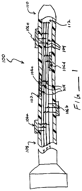
As shown, for instance, in FIGS. 1A, 1B, and 1C, microstimulator device 100 may include a narrow, elongated capsule 102 containing electrical circuitry 104 connected to electrodes 110, which may pass through or comprise a part of the walls of the capsule, as in FIG. 1A. Alternatively, electrodes 110 may be built into the capsule (FIG. 1B) or arranged along a lead(s) 112 (FIG. 1C), as described below. As detailed in the referenced patent publications, electrodes 110 generally comprise a stimulating electrode, or cathode (to be placed close to the target tissue) and an indifferent electrode, or anode (for completing the circuit). Other configurations of microstimulator device 100 are possible, as is evident from the above-referenced publications, and as described in more detail herein.
Microstimulator 100 may be implanted via a minimal surgical procedure. Microstimulator 100 may be implanted with a surgical insertion tool specifically designed for the purpose, or may be placed, for instance, via a small incision and through an insertion cannula. Alternatively, microstimulator 100 may be implanted via conventional surgical methods, or may be inserted using other endoscopic or laparoscopic techniques. A more complicated surgical procedure may be required for sufficient access to a nerve or a portion of a nerve (e.g., nerve fibers surrounded by scar tissue, or more distal portions of the nerve) and/or for fixing the neurostimulator in place.
The external surfaces of microstimulator 100 may advantageously be composed of biocompatible materials. Capsule 102 may be made of, for instance, glass, ceramic, or other material that provides a hermetic package that will exclude water vapor but permit passage of electromagnetic fields used to transmit data and/or power. Electrodes 110 may be made of a noble or refractory metal or compound, such as platinum, iridium, tantalum, titanium, titanium nitride, niobium, or alloys of any of these, in order to avoid corrosion, electrolysis, or other electrochemical reactions which could damage the surrounding tissues and the device.
Microstimulator 100 contains, when necessary and/or desired, electrical circuitry 104 for receiving data and/or power from outside the body by inductive, radio-frequency (RF), or other electromagnetic coupling. In some embodiments, electrical circuitry 104 includes an inductive coil for receiving and transmitting RF data and/or power, an integrated circuit (IC) chip(s) for decoding and storing stimulation parameters and generating stimulation pulses (either intermittent or continuous), and additional discrete electrical components required to complete the electrical circuit functions, e.g. capacitor(s), resistor(s), coil(s), diode(s), and the like.
Microstimulator 100 includes, when necessary and/or desired, a programmable memory 114 (which may be a part of the electrical circuitry 104) for storing a set(s) of data, stimulation, and/or control parameters. Among other things, memory 114 may allow stimulation and control parameters to be adjusted to settings that are safe and efficacious with minimal discomfort for each individual. In addition, this allows the parameters to be adjusted to ensure that the stimulation favors unidirectional propagation, when desired. The device(s) may be implanted to deliver electrical stimulation to any location that is likely to be therapeutic, and the stimulation parameters may be adjusted to any set of parameters that prove efficacious, as described herein. Specific stimulation sites and parameters may provide therapeutic advantages for various medical conditions, their forms, and/or severity. For instance, some patients may respond favorably to intermittent stimulation, while others may require continuous stimulation to alleviate their symptoms. Therefore, various embodiments of the invention include means for providing stimulation intermittently and/or continuously.
The present invention provides means of maintaining the advantages of earlier BION microstimulator systems while extending their functionality to enable, inter alga, programmably configurable multielectrode systems that allow current to be more effectively directed towards a target stimulation site. For instance, possible microstimulator configurations have one or more programmably configurable electrodes 110 arranged along the stimulator outer capsule, as shown in FIG. 2A. Thus, a microstimulator 100 may have a combination of programmably configurable and hard-wired electrodes, or may have only programmably configurable electrodes, or may have only a plurality of hard-wired electrodes.
The configuration of microstimulator 100 may be determined by the structure of the desired target, the surrounding area, and the method of implantation. The size and the shape of the microstimulator may be varied in order to deliver more effective treatment. A thin, elongated cylinder with electrodes at the ends and/or along the cylindrical case are possible configurations, but other shapes, such as disks, spheres, helical structures, and others are possible. Additional alterations in configuration, such as the number, orientation, and shape of electrodes (which may be programmably configurable), may be varied in order to deliver more effective treatment. For instance, the electrodes may be rectangular, semi-spherical, arcs, bands/rings, or any other useful shape, and may be distributed along and/or around the surface of the microstimulator.
Implantable microstimulator 100 is sufficiently small to permit its placement in or near the structures to be stimulated. For instance, capsule 102 may have a diameter of about 4-5 mm, or only about 3 mm, or even less than 3 mm. Capsule 102 length may be about 25-40 mm, or only about 20-25 mm, or even less than 20 mm. In some configurations and for some stimulation sites, it may be useful for microstimulator 100 to be larger, to be of a different shape, or to include a lead(s) 112, as described in more detail below.
In some embodiments of the instant invention, microstimulator 100 comprises two or more leadless electrodes. However, one or more electrodes 110 may alternatively be located along short, flexible leads 112 (FIG. 1C) as described in U.S. patent application Ser. No. 09/624,130, filed Jul. 24, 2000, which is incorporated herein by reference in its entirety. The use of such leads permits, among other things, electrical stimulation to be directed more locally to targeted tissue(s) a short distance from the surgical fixation of the bulk of the implantable microstimulator 100, while allowing most elements of the microstimulator to be located in a more surgically convenient site and/or in a position making telemetry with and/or powering and/or replacing or removing the device simpler. This minimizes the distance traversed and the surgical planes crossed by the device and any lead(s). Other uses of such configurations will be apparent presently. For instance, the electrodes may be positioned on a cuff(s) attached to the microstimulator via a lead(s), as described below. In most uses of this invention, the leads are no longer than about 150 mm.
A microstimulator including a cuff electrode, as shown in FIGS. 2B, 2C, and 2D, may be a tripolar cuff electrode 116, possibly with an asymmetric placement of the center electrode. The electrodes may substantially form a ring, or the electrodes may be partitioned. Other cuff electrode configurations, as known to those of skill in the art, may alternatively or additionally be used. Such a cuff electrode may be a bipolar cuff electrode 118 with the anode placed farther from the nerve than the cathode via the use of an insulating sheath of larger diameter for the anode than the cathode.
According to one embodiment of the invention, a microstimulator is attached to the cuff electrode via a lead 112. According to another embodiment of the invention, the cuff electrode is incorporated into the microstimulator package, e.g., a microstimulator with a cuff electrode attachment or other microstimulator fixation device 130, as in U.S. patent application Ser. No. 10/146,332 (the '332 application), which application is incorporated herein by reference in its entirety. As discussed in the '332 application, fixation device 130 may include one or more electrodes 110. Examples of microstimulator cuff electrode attachments/fixation devices 130 that may be used with the present invention are shown in, but not limited to, FIGS. 2B, 2C, 2D, 3A, 3B, and 3C.
In some applications, a microstimulator having a single cathode may be sufficient. For instance, in some applications, such as pudendal nerve stimulation for urge incontinence, the target may be rather large in at least one dimension, allowing for some positioning error. However, for some, applications, a single cathode microstimulator may prove insufficient or imperfect. For instance, if a target site is very small in all dimensions, the microstimulator may be difficult to place precisely. For example, in deep brain stimulation for Parkinson's disease, the subthalamic nucleus has a maximum dimension of only 4-7 mm. Precisely placing the microstimulator at this target is likely to be difficult, and even slight migration of the microstimulator over time may reduce its efficacy. Other stimulation target sites may be physically constrained, so that the microstimulator cannot be or is difficult to position ideally in relation to the stimulation target. For example, the trigeminal ganglion, which receives sensation from all of the sensory nerves of the face, sits in a dural compartment known as the trigeminal (Meckel's) cave, which lies in a depression on the anterior slope of the petrous portion of the temporal bone. The trigeminal cave is a rather confined space that is surrounded by bone, and a solid device, even a microstimulator, may not be easy to manipulate and precisely position in such a space.
In addition, in configurations where the microstimulator electrodes are cylindrical (either on a lead or on the case of a cylindrical microstimulator), the stimulation current is generally directed 360 degrees radially outward. However, the target neurons may be located only to one side of the electrode(s). Such a situation can result in higher thresholds (due to wasted current directed away from the neural targets) as well as undesired stimulation of neurons that are not the desired targets of stimulation. Solutions to this problem may involve locating the electrodes to one side of the array. However, lead or microstimulator migration or rotation can make such designs ineffective or cumbersome to deploy and maintain.
The programmably configurable multielectrode microstimulators of the present invention, which can be "electrically positioned" as described herein, address these and other problems. In certain embodiments, such as shown in FIG. 2A, the microstimulator has a cylindrical shape, with electrodes 110 configured as a plurality of anodes, cathodes, and/or open circuit electrodes distributed along its surface. One or both ends may be capped with an electrode 110, and one or more electrodes may be arranged along the microstimulator outer case.
In various embodiments, the end cap electrode(s) and/or those along the length of the microstimulator and/or those on a lead attached to a microstimulator can be further divided as shown in FIG. 2E into "partitioned" electrodes. Thus, individual electrodes, rather than extending completely around the microstimulator, are partitioned into short arcs. In between each of the partitioned electrodes 110 is an insulating material 120 to provide some electrical isolation. In an extreme alternative, the microstimulator could be covered with small arcs of electrodes along its entire surface. The size of the electrodes 110 and the insulating areas 120 may be uniform or may be independent and varied.
The description continues in the full USPTO document.
 Lapsed, fee not paid19 drawings