Cross-reference to related application
This application is related to Japanese Patent Application No. 2010-184285 filed on Aug. 19, 2010, whose priority is claimed and the disclosure of which is incorporated by reference in its entirety.
Background of the invention
1. Field of the invention
The present invention relates to a fusing apparatus used in an electrophotographic system, an image forming apparatus provided with the same, and a heating apparatus having a sheet heating element.
2. Description of the related art
An image forming apparatus using an electrophotographic process (hereinafter merely referred to as an "image forming apparatus") includes a photoconductor, a charging unit, an exposure unit, a developing unit, a transfer unit, and a fusing unit, for example. The image forming apparatus performs a charging process, an exposure process, a developing process, a transfer process, and a fusing process with the use of the photoconductor and these units, whereby forming an image onto a sheet-type recording medium (hereinafter merely referred to as a "sheet").
A fusing apparatus of a thermal roller fusing system is used, for example, as the fusing unit that performs the fusing process. The fusing apparatus of the thermal roller fusing system includes a fuser roller and a pressure roller. The fuser roller and the pressure roller are a pair of rollers that are in pressed contact with each other. At least either one of the fuser roller and the pressure roller includes a heat source serving as a heating unit, such as a halogen heater, mounted therein.
In the fusing process, the heat source heats the roller pair to a predetermined temperature required for the fusing (hereinafter referred to as a "fusing temperature"). Thereafter, the recording medium having a non-fused toner image formed thereon is conveyed to a fuser nip portion that is a press-contact portion between the fuser roller and the pressure roller. The non-fused toner image is fused onto the recording medium such as a sheet due to the heat transmitted from at least either one of the fuser roller and the pressure roller and the pressure from the fuser roller and the pressure roller, when it passes through the fuser nip portion. Although the temperature of the portion of the nip portion where the recording medium passes (hereinafter referred to as a "sheet passing portion") is decreased, the temperature of the sheet passing portion then rises to the fusing temperature, since the heat is supplied from the heat source.
A fusing apparatus provided to an image forming apparatus capable of performing a full-color printing uses a fuser roller provided with an elastic layer made of a silicon rubber on its surface (hereinafter referred to as an "elastic roller"). For forming a full-color image in which a plural colors of toners are used, more toner needs to be fused compared to the case of a monochrome image. When the elastic roller is used, the surface of the elastic roller is elastically deformed corresponding to irregularities on the non-fused toner image at the fuser nip portion. Specifically, the elastic roller and the non-fused toner image are brought into contact with each other as if the elastic roller covers the non-fused toner image. Therefore, a fusibility for fusing the full-color image, which uses a lot of toner, can be enhanced. A releasing performance of a color toner, which is liable to be offset compared to a monochrome image, can be enhanced due to an effect of releasing a distortion of the elastic layer on the surface of the elastic roller. Specifically, on the elastic layer that is compressed and deformed at the fuser nip portion, the deformation is released at an exit of the fuser nip portion. Therefore, a deviation is generated between the elastic layer and the toner image at the exit of the fuser nip portion. As a result, an adhesion force of the elastic layer to the toner image is reduced, resulting in that the releasing performance is enhanced. Since the elastic layer is deformed to have a concave shape due to the press-contact between the fuser roller and the pressure roller at the fuser nip portion, the shape (nip shape) of the path through which the recording medium passes becomes convex toward the fuser roller. Therefore, the curvature of the surface of the fuser roller at the portion where the recording medium is separated from the fuser roller increases, resulting in that a separation property of the recording medium can be enhanced. As a result, a structure of being capable of separating the recording medium from the fuser roller (self-stripping structure) can be realized without providing an auxiliary separating unit, e.g., a separating claw, for separating the recording medium from the fuser roller. This structure can avoid the formation of a defective image caused by the separating unit.
In order to respond to an increased speed in an image formation, the width of the fuser nip portion (hereinafter referred to as "fuser nip width") is necessarily widened. There are two methods, which are a method of increasing the thickness of the elastic layer of the elastic roller, and a method of increasing the diameter of the elastic roller, as a method of increasing the fuser nip width. However, a thermal conductivity of the elastic layer of the elastic roller is extremely low. When the thickness of the elastic layer of the elastic roller increases in a structure in which the heating unit is provided in the elastic roller as in the conventional case, a thermal conductivity from the inside of the elastic roller to the surface thereof is deteriorated, which might increase a warm-up time. When a process speed involved with the image formation is increased, a peripheral speed of the fuser roller has to be increased corresponding to the increased process speed. However, the recovery of the temperature of the fuser roller, which is reduced at the sheet passing portion, is too late, which entails a problem that the temperature of the fuser roller cannot follow the fusing temperature. When the diameter of the elastic roller is increased in order to secure the time for the temperature recovery, a power consumption of the heating unit might increase.
A fusing apparatus of a belt fusing system is described in Pamphlet of International Publication No. WO99/00713 in order to solve the foregoing problems. The belt fusing system includes a fuser roller, a pressure roller, a heat roller, and an endless belt. The endless belt is stretched between the heat roller having a heater provided therein and the fuser roller, wherein the fuser roller and the pressure roller are in contact with each other via the endless belt. In the belt fusing system, the heat roller serving as the heating unit heats the endless belt having a small heat capacity, whereby a warm-up time can be shortened, compared to the structure in which the elastic layer having a large heat capacity is heated. Since the heating unit does not have to be incorporated in the fuser roller, the deterioration in the thermal conductivity does not become a problem, even if the elastic layer made of a sponge rubber, for example, having a low hardness is formed to be thick, resulting in that the wide fuser nip portion can be secured.
Japanese Unexamined Patent Publication No. 7-201455 proposes a fuser of a film heating system. In the film heating system, a sheet heating element is used as the heating unit, wherein a heat from the heating unit is applied to a recording material, serving as a material to be heated, through a film. A non-fused image on the recording material is fused by the heat as a permanent image.
In the fusing apparatus of the film heating system, the heat capacity of the sheet heating element is smaller than the heat capacity of a conventional halogen lamp heater. Specifically, the heat capacity of the heating unit can be reduced more than in the conventional case, whereby power saving can be attained, and the warm-up time can be shortened.
The present inventors have developed a fusing apparatus using a fuser belt of an endless belt type. A fuser apparatus according to the present invention includes a fuser belt that is stretched between a fuser roller and a tension roller to form a loop-type moving path, wherein a heating member is brought into contact with an inner side of the stretched fuser belt so as to heat the fuser belt, as illustrated in a later-described FIG. 3. The fuser belt is in contact with a pressure roller at a press-contact point between the fuser roller and the pressure roller opposite to the fuser roller. A recording medium having a toner image transferred thereon is guided to the press-contact point between the pressure roller and the fuser belt, wherein the toner image is heated and fused by the fuser belt to be fixed onto the recording medium.
The heating member includes, in this order from the fuser belt, a heat-conductor, a sheet heating element, a heat insulating member, a pressure member, and a reinforcing member.
As illustrated in a later-described FIGS. 5A and 5B, the sheet heating element includes plural resistance heating layers that are formed on a surface of a substrate which has a slender shape in a widthwise direction so as to extend in a longitudinal direction of the substrate. One end and the other end of each of the resistance heating layers are connected by end electrodes. A conduction portion extending in the widthwise direction of the substrate is formed at plural places at a middle portion sandwiched between the end electrodes at both ends, wherein the different resistance heating layers are connected by the conduction portion. The heat-conductor is made of a material having excellent thermal conductivity such as an aluminum that is a rigid body. The pressure member presses the sheet heating element against the heat-conductor so as to efficiently transfer a heat from the sheet heating element to the fuser belt.
In the fusing apparatus having the above-mentioned configuration, the present inventors have found problems described below involved with a setting of a pressure position where the sheet heating element is pressed against the heat-conductor.
Pressure Position at Central Portion in Longitudinal Direction of Substrate
In the present invention, the conduction portion is formed at plural positions in the longitudinal direction for connecting in the widthwise direction of the substrate the different resistance heating layers, in order to average a variation in the resistance of the respective parallel resistance heating layers in the longitudinal direction of the substrate. The resistance heating layers are divided into several blocks in the longitudinal direction thereof by forming the conduction portion, wherein the respective blocks are electrically connected in series. This is to average a variation in a unit of the block so as to reduce a temperature unevenness, even if there is the variation in the resistance value of the parallel resistance heating layers composing each block.
When the pressure position is close to the conduction portion in this case, the substrate thermally expands at the adjacent conduction portions to warp, with the result that a gap is formed between the sheet heating element and the heat-conductor. When the gap is locally formed in the longitudinal direction of the substrate, a transfer of the heat at this portion is hindered, resulting in that the temperature of the sheet heating element is locally increased. If so, this portion further expands thermally, which causes a significant warp. In an extreme case, the substrate is broken, or the resistance heating layer is fused by the heat, so that a uniform heat generation cannot be attained. Although the substrate is not broken or the substrate does not become defective, a problem arises in which a temperature unevenness is caused in the longitudinal direction of the substrate.
Pressure Position at End in Longitudinal Direction of Substrate
As for the pressure position in the vicinity of the end of the sheet heating element, when the pressure position is set within a fixed range closer to the center than to the end of the resistance heating layer, the sheet heating element thermally expands to warp, resulting in that a gap is formed between the heat-conductor and the sheet heating element. As a result, the substrate is broken, or the resistance heating layer is locally fused, as in the case of (1). Although the substrate is not broken or the substrate does not become defective, a problem arises in which a temperature unevenness is caused in the longitudinal direction of the substrate.
These problems are unique to the present structure in which the sheet heating element is pressed against the rigid member. Specifically, Pamphlet of International Publication No. WO99/00713 and the present invention are different from each other in that the sheet heating element is pressed against the elastic member such as the pressure roller or the rigid member such as a member made of an aluminum. According to the configuration of the present invention, there is no chance that the sheet heating element is pressed against the elastic member having large heat capacity, whereby the configuration is advantageous from a viewpoint of power saving and shortening the warm-up time. On the contrary, Pamphlet of International Publication No. WO99/00713 describes the configuration in which the sheet heating element is pressed against the pressure roller, which is the elastic member, via the fuser belt, so that this configuration is disadvantageous in power saving and shortening the warm-up time. However, the deformation of the sheet heating element due to the warp is absorbed by the pressure roller, which is the elastic member, so that a gap is difficult to be formed. Therefore, the gap is not formed between the sheet heating element and the pressure roller, which means the problem in the present invention involved with the pressure position hardly arises.
Summary of the invention
The present invention has been accomplished based upon the above-mentioned knowledge that has been found by the present inventors, and aims to provide a stable and robust fusing apparatus that can attain a uniform heating, while achieving power saving and shortening the warm-up time, and that is not broken or that is not defective. More specifically, in the fusing apparatus having a configuration in which a sheet heating element is pressed against a rigid member serving as a heat-conductor, an appropriate position for pressing the sheet heating element is selected, whereby a uniform heating and a robust and stable configuration can be realized.
The present invention provides
a fusing apparatus including: a sheet heating element for generating heat to fix a toner image being transferred onto a sheet; an endless belt being rotatably stretched by a stretching member; a rigid member for conducting the heat to the endless belt as a heat-conductor, the rigid member being arranged to contact with the sheet heating element and the endless belt respectively; and a pressure member for pressing the sheet heating element against the rigid member, wherein the endless belt is arranged to contact with the sheet, the sheet heating element includes an elongated substrate extending in a widthwise direction of the endless belt perpendicular to the rotating direction thereof, a plurality of parallel resistance heating layers which are formed on a surface of the substrate along a longitudinal direction of the substrate, and at least one conduction portion formed in at least one place of an intermediate region between one end and another of each resistance heating layer to connect the different resistance heating layers, and wherein the pressure member presses the sheet heating element against the rigid member at a position other than positions where the conduction portion is formed.
The present invention also provides an image forming apparatus provided with the fusing apparatus.
The present invention also provides
a heating apparatus including: a sheet heating element for generating heat to fix a toner image being transferred onto a sheet, the sheet heating element including an elongated substrate, a plurality of parallel resistance heating layers which are formed on a surface of the substrate along a longitudinal direction thereof and arranged parallel to one another, and at least one conduction portion formed in at least one place of an intermediate region between one end and another of each resistance heating layer to connect the different resistance heating layers; a rigid member in contact with an object to be heated for conducting the heat from the sheet heating element to the object; and a pressure member for pressing the sheet heating element against the rigid member, wherein the pressure member presses the sheet heating element against the rigid member at a position other than a position where the conduction portion is formed.
The present invention also provides
a fusing apparatus including: an endless belt being arranged to contact with a sheet with a toner image being transferred thereon; a pair of rollers for sandwiching the endless belt from inside and outside to rotate the endless belt and conveying the sheet with the toner image by sandwiching the sheet as well as the endless belt; a sheet heating element for generating heat to fix the toner image onto the sheet; a rigid member for conducting the heat to the endless belt as a heat-conductor, the rigid member being arranged to contact with the sheet heating element and the endless belt, respectively and stretch the endless belt; a pressure member for pressing the sheet heating element against the rigid member; and a counter member arranged to be opposite to the rigid member via the endless belt; wherein the counter member presses the endless belt against the rigid member.
The present invention also provides
a fusing apparatus comprising: a sheet heating element for generating heat to fix a toner image being transferred onto a sheet; an endless belt being rotatably stretched by two or more stretching members; a rigid member for conducting the heat to the endless belt as a heat-conductor, the rigid member being arranged to contact with the sheet heating element and the endless belt, respectively; a pressure member for pressing the sheet heating element against the rigid member; and a counter member arranged to oppose to the rigid member via the endless belt; wherein the rigid member and the counter member are arranged between the stretching members, and the counter member presses the endless belt against the rigid member.
Brief description of the drawings
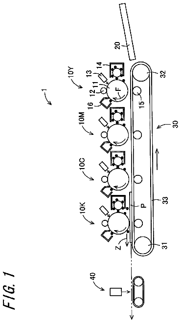
FIG. 1 is an explanatory view schematically illustrating a configuration of an image forming apparatus according to one embodiment of the present invention;
FIG. 2 is an explanatory view schematically illustrating an example of a configuration of an image forming unit in the image forming apparatus illustrated in FIG. 1;
FIG. 3 is a sectional view illustrating an example of a detailed configuration of a fusing portion in the image forming apparatus illustrated in FIG. 1;
FIG. 4 is an explanatory view illustrating a state in which a gap is formed between a heat-conductor and a sheet heating element in the vicinity of an end of the heat-conductor in a conventional fusing apparatus;
FIGS. 5A and 5B are explanatory views illustrating an example of a detailed configuration of the sheet heating element in the image forming apparatus illustrated in FIG. 1;
FIG. 6 is an explanatory view illustrating a detail of a pressure position in an experiment example 1 in the present invention;
FIG. 7 is an explanatory view illustrating a detail of a pressure position in an experiment example 2 in the present invention;
FIG. 8 is an explanatory view illustrating a detail of a pressure position in an experiment example 3 in the present invention;
FIG. 9 is a sectional view illustrating an example of a configuration, different from FIG. 3, of the fusing portion in the image forming apparatus illustrated in FIG. 1;
FIG. 10 is an explanatory view illustrating a configuration in which a cleaning web is arranged at a counter member in the fusing apparatus according to the present invention; and
FIG. 11 is an explanatory view illustrating a modification of the fusing apparatus illustrated in FIG. 9.
Detailed description of the invnetion
In the fusing apparatus in
of the present invention, the sheet heating element includes plural parallel resistance heating layers extending in the longitudinal direction of the substrate, and a conduction portion that is formed on at least one portion at the middle portion sandwiched between one end and the other end of the respective resistance heating layers so as to connect the different resistance heating layers, wherein the pressure member presses the sheet heating element against the rigid member in the longitudinal direction of the substrate except for the portion where the conduction portion is formed. Therefore, the pressure member presses the resistance heating layer, which generates heat during an energization, except for the portion of the conduction portion that generates less heat, in other words, the pressure member presses against the portion having a large thermal expansion, in order to effectively prevent the formation of a gap between the substrate and the heat-conductor due to the thermal expansion. Specifically, an appropriate position for pressing the sheet heating element is selected, whereby the fusing apparatus that attains a uniform heating and that has a robust and stable configuration can be realized.
The heating apparatus in
includes the sheet heating element having plural parallel resistance heating layers extending in the longitudinal direction of the substrate, and a conduction portion that is formed on at least one portion at the middle portion sandwiched between one end and the other end of the respective resistance heating layers so as to connect the different resistance heating layers; the rigid member that conducts the heat from the sheet heating element to an object to be heated; and a pressure member that presses the sheet heating element against the rigid member, wherein the pressure member presses the sheet heating element against the rigid member in the longitudinal direction of the substrate except for the portion where the conduction portion is formed. Therefore, the pressure member presses the resistance heating layer, which generates heat during an energization, except for the portion of the conduction portion that generates less heat, in other words, the pressure member presses against the portion having a large thermal expansion, in order to effectively prevent the formation of a gap between the substrate and the heat-conductor due to the thermal expansion. Specifically, an appropriate position for pressing the sheet heating element is selected, whereby the fusing apparatus that attains a uniform heating and that has a robust and stable configuration can be realized.
The fusing apparatus described in
includes the rigid member that functions as the heat-conductor and that stretches the endless belt, and the counter member that is arranged so as to be opposite to the rigid member via the endless belt, wherein the counter member presses the endless belt against the rigid member. Therefore, this configuration can effectively prevent the formation of the gap between the rigid member serving as the heat-conductor and the endless belt. Accordingly, the endless belt can efficiently and uniformly be heated.
The fusing apparatus described in
includes the rigid member serving as the heat-conductor, and the counter member that is arranged so as to be opposite to the rigid member, wherein the rigid member and the counter member are arranged between two stretching members, and the counter member presses the endless belt against the rigid member. Therefore, this configuration can effectively prevent the formation of the gap between the rigid member serving as the heat-conductor and the endless belt. Accordingly, the endless belt can efficiently and uniformly be heated.
The fusing apparatus according to the present invention heats the endless belt to fuse the toner image transferred onto a sheet-type transfer material with the heat, thereby fixing the toner image onto the transfer material. An image forming apparatus of an electrophotographic system generally has the fusing apparatus of this type. The present invention is applicable to an apparatus other than the electrophotographic system, so long as it heats a toner and fuses the toner onto a sheet, regardless of image forming systems. In a later-described embodiment, the fusing apparatus corresponds to a fusing portion.
The heating apparatus according to the present invention is a heat source preferable to the fusing apparatus, and is a long slender apparatus including a plane or plate-like heating element, a rigid member whose surface is preferably formed into a humpbacked shape having a gentle curvature, and a pressure member that presses the heating element against the rigid member. The heating apparatus heats the subject to be heated with the surface of the rigid member being in contact with the subject to be heated. In the later-described embodiment, the heating apparatus corresponds to a heating member.
The image forming apparatus according to the present invention includes the fusing apparatus. The specific example thereof is a printing apparatus of an electrophotographic system.
The sheet is a recording medium on which an image, which is to be printed thereon, is formed with a toner and fused. The typical example of the sheet is a print sheet. However, the sheet is not limited to a paper. The sheet may be a transparent resin used for an overhead projector, or a non-transparent resin.
In the fusing apparatus according to the present invention, the endless belt is brought into intimate contact with the sheet as being heated by the heating member so as to allow the toner transferred onto the sheet to be fused on the sheet. In the later-described embodiment, the endless belt corresponds to a fuser belt. The specific embodiment thereof is a belt having a silicon rubber, serving as an elastic layer, with a thickness of about 150 .mu.m coated on a polyimide base having a thickness of about 100 .mu.m, and a fluorine resin coated thereon in order to enhance a releasing performance. It is to be noted that the belt is not limited thereto, so long as it has a heat resistance property and flexibility.
The stretching members stretch the endless belt so as to be rotatable. The specific example thereof is a roller or a member having a fan-like surface. The fuser belt is stretched on the stretching members. In the later-described embodiment, the stretching members correspond to a fuser roller and a tension roller. Alternatively, the heating member may have a fan-like surface, and serve as the stretching member as applying tension to the endless belt by the fan-like portion.
The sheet heating element is a heat source that heats the endless belt through an electric heating member, wherein at least the portion that is in contact with the electric heating member is planar. The specific embodiment thereof is an element formed in such a manner that a resistance pattern, having an alloy (AgPd) of silver and palladium as a major component, in a form of a paste is printed and sintered on a ceramic substrate having a reed shape, and an insulating material such as a glass is coated on its surface. The material for the substrate and the resistance and the production method are not limited thereto.
The resistance heating layer is a resistance body that generates heat when it is energized. The specific embodiment is the one formed by sintering a paste of silver and palladium as described above. The material and the production method are not limited thereto. In the present invention, plural resistance heating layers are arranged in parallel along the longitudinal direction of the substrate. A voltage is applied between one end and the other end of each of the resistance heating layers, whereby an electric current flows through the resistance heating layers. Accordingly, the resistance heating layers generate heat according to Joule heat.
The conduction portion is a conduction layer that is provided in a middle portion between one end and the other end of each of the resistance heating layers, which are arranged in parallel, in order to connect different resistance heating layers. Preferably, several conduction portions are formed in the middle part. The resistance heating layers are connected at several parts and divided into a block. Therefore, even if there is a local resistance variation in the resistance heating layers, the variation is averaged in a unit of the block, whereby the heat generation can be made uniform. The specific embodiment is, for example, the one formed by printing and sintering a conductive pattern, having silver as a major component, in the form of a paste.
The rigid member transfers the heat from the sheet heating element to the endless belt. The specific embodiment is, for example, a member that is made of an aluminum, and formed to have a convex shape in which the surface that is in contact with the sheet heating element is formed to be flat, but the surface that is in contact with the endless belt is formed to have a gentle curvature. A fluorine resin is coated on the surface of the rigid member. The material is not limited thereto, so long as it has a heat resistance property, and a high thermal conductivity. The fluorine resin is coated in order to satisfactorily move the endless belt in a sliding manner. However, the coating may not be performed.
The pressure member is a member for pressing the sheet heating element against the heat-conductor. The specific embodiment thereof is, for example, a plate spring made of a stainless. The material is not particularly limited, so long as it has a heat resistance property and elasticity.
A preferable embodiment of the present invention will be described below.
In the fusing apparatus described in
in the present invention, the sheet heating element may include plural conduction portions, and the pressure member may press the sheet heating element against the rigid member at a middle portion between two conduction portions adjacent each other. With this configuration, the position at the middle of the adjacent conduction portions, i.e., the position at the middle of the resistance heating layers that generate heat upon energization, can be pressed. Since the portion having a large thermal expansion is pressed, the formation of the gap between the substrate and the heat-conductor due to the thermal expansion can more effectively be prevented. Specifically, an appropriate position for pressing the sheet heating element is selected, whereby the fusing apparatus that attains a uniform heating and that has a robust and stable configuration can be realized.
Alternatively, the pressure member may press the sheet heating element against the rigid member at a position that is between two conduction portions adjacent each other and is more than or equal to 10 mm away from both of respective conduction portions. With this configuration, the portion sufficiently apart from the conduction portion that generates less heat during the energization, i.e., the portion having a large thermal expansion, can be pressed. Therefore, the formation of the gap between the substrate and the heat-conductor due to the thermal expansion can more effectively be prevented. Specifically an appropriate position for pressing the sheet heating element is selected, whereby the fusing apparatus that attains a uniform heating and that has a robust and stable configuration can be realized.
In the preferable embodiment of the present invention, one end of the rigid member may be substantially at a same position as one end of each resistance heating layer in the a longitudinal direction of the substrate, and the pressure member may press the sheet heating element against the rigid member at a position between the one end of each resistance heating layer and the conduction portion near the end of each resistance heating layer. With this configuration, although the substrate is liable to warp due to the thermal expansion with one end of the rigid member being defined as a support at the end of the substrate, the portion, where the resistance heating layer is present, between the position substantially equal to one end described above and the conduction portion closest to the position can be pressed. Accordingly, the formation of the gap between the end of the substrate and the heat-conductor can effectively be prevented. Specifically, an appropriate position for pressing the sheet heating element at the end of the substrate is selected, whereby the fusing apparatus that attains a uniform heating and that has a robust and stable configuration can be realized.
Further, the pressure member may press the sheet heating element against the rigid member at a middle portion between the one end of each resistance heating layer and the nearest conduction portion from the end of each resistance heating layer. With this configuration, at the end of the substrate, the position at the middle of one end of each of the resistance heating layers and the conduction portion, i.e., the portion at the middle of the resistance heating layers that generate heat during the energization, can be pressed. Accordingly, the formation of the gap between the substrate and the heat-conductor can effectively be prevented. Specifically, an appropriate position for pressing the sheet heating element is selected, whereby the fusing apparatus that attains a uniform heating and that has a robust and stable configuration can be realized.
Alternatively, the pressure member may press the sheet heating element against the rigid member at a position that locates between the one end of each resistance heating layer and the nearest conduction portion from the end of each resistance heating layer and that locates anywhere within more than or equal to 10 mm from the end of each resistance heating layer. With this configuration, although the substrate is liable to warp due to the thermal expansion with one end of the rigid member being defined as a support at the end of the substrate, the portion sufficiently apart from one end described above can be pressed. Accordingly, the formation of the gap between the substrate and the heat-conductor due to the thermal expansion can more effectively be prevented. Specifically, an appropriate position for pressing the sheet heating element is selected, whereby the fusing apparatus that attains a uniform heating and that has a robust and stable configuration can be realized.
The sheet heating element may have a resistance heating layer made of silver and palladium with a thickness of about 10 .mu.m on a ceramic substrate having a thickness of about 0.8 mm.
The pressure member may be made of an elastic member, or may be made of a stainless plate spring.
The rigid member may be made of an aluminum.
In the fusing apparatus described in (3), the counter member may serves as a cleaning member for cleaning the endless belt. With this configuration, a function as the counter member and a function as a cleaning member can be realized with a simple configuration.
In the fusing apparatus described in (4), it may be configured as the counter member may serves as a cleaning member for cleaning the endless belt. With this configuration, a function as the counter member and a function as a cleaning member can be realized with a simple configuration.
Various preferable embodiments described above can be combined to each other.
The present invention will be described below in more detail with reference to the drawings. The description below is only illustrative for all points, and it should not be construed that the present invention is limited by the description below.
Embodiment 1
FIG. 1 is a diagram schematically illustrating a configuration of an image forming apparatus 1 that is one embodiment of the present invention. The image forming apparatus 1 includes an image forming portion 2, an intermediate transfer portion 3, a secondary transfer portion 4, a recording medium feeding portion 5, and a fusing portion 6 that is a fusing apparatus according to the present invention, as well as a display portion, an operation portion, and a control portion, which are not illustrated in FIG. 1.
The fusing portion 6 will be described below. The detailed configurations of the other portions will be described at the end of this specification.
(Fusing Portion)
FIG. 3 is a sectional view illustrating the configuration of the fusing portion 6. The fusing portion 6 serving as a fusing unit includes a fuser belt 71, a fuser roller 50, a tension roller 77, a heating member 80, and a pressure roller 60.
The fuser belt 71 is an endless belt-like member that is stretched between the fuser roller 50 and the tension roller 77 for forming a loop-type moving path. The fuser belt 71 is mounted so as to be in contact with the pressure roller at a press-contact point between the fuser roller 50 and the pressure roller 60. The fuser belt 71 heats and fuses a toner, forming a toner image carried onto a recording medium 8, to be fixed onto the recording medium 8. The fuser belt 71 rotates in a direction of an arrow 78 with the rotation of the pressure roller 60 in a direction of an arrow 55.
In the present embodiment, an endless belt having a three-layer structure including a base layer 72, an elastic layer 73, and a release layer 74, and formed into a cylindrical shape having a diameter of 50 mm, is used as the fuser belt 71.
A material made of the base layer 72 is not particularly limited, so long as it is excellent in heat resistance property and durability. A heat-resistant synthetic resin can be used as the material of the base layer 72. Preferable examples thereof include polyimide (PI), polyamideimide (PAI), nickel plating, and SUS. These materials are excellent in strength, heat resistance property, and cost performance.
The thickness of the base layer 72 is not particularly limited, but preferably, 30 to 200 .mu.m.
A material of the elastic layer 73 is not particularly limited, so long as it has a rubber elasticity. A material having excellent heat resistance property is preferable. Specific examples thereof include a silicon rubber, fluorine-containing rubber, and fluorosilicon rubber, wherein the silicon rubber that is more excellent in the rubber elasticity is more preferable.
A hardness of the elastic layer 73 is preferably 1 to 60 degrees in JIS-A hardness. When the hardness falls within the range of the JIS-A hardness, a defective fusibility of the toner can be prevented, while preventing the reduction in the strength of the elastic layer 73 and a poor adhesive property. Specific examples of the silicon rubber include a silicon rubber containing one component, two components, or three or more components, a silicon rubber of LTV type, RTV type, or HTV type, and a condensed or addition silicon rubber.
The thickness of the elastic layer 73 is preferably 100 to 200 .mu.m. When the thickness falls within this range, a heat insulating property can be held to be low, while keeping an elastic effect of the elastic layer 73, whereby an energy-saving effect can be exhibited. In the present embodiment, a silicon rubber having JIS-A hardness of 5 degrees is used.
The release layer 74 is made of a layer formed by applying a resin containing a fluorine resin tube or a fluorine resin, and sintering the resultant.
The description continues in the full USPTO document.
 Lapsed, fee not paid4 drawings