 Lapsed, fee not paid20 drawings
Hardware & Electronics · US 8,711,736 B2
Audio processing in a multi-participant conference
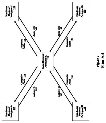
A first computing device distributes audio signals to several computing devices of participants in a communication session.
US 8,711,763 B2 · Assignee: QUALCOMM Incorporated · Inventors: Walton; Jay Rodney et al.
Sheet 1 of 12 from the published document. All sheets in the USPTO PDF
Techniques for facilitating random access in wireless multiple-access communication systems are described. A random access channel (RACH) is defined to comprise a "fast" RACH (F-RACH) and a "slow" RACH (S-RACH). The F-RACH and S-RACH can efficiently support user terminals in different operating states and employ different designs. The F-RACH can be used to quickly access the system, and the S-RACH is more robust and can support user terminals in various operating states and conditions. The F-RACH may be used by user terminals that have registered with the system and can compensate for their round trip delays (RTDs) by properly advancing their transmit timing. The S-RACH may be used by user terminals that may or may not have registered with the system, and may or may not be able to compensate for their RTDs. Other aspects, embodiments, and features are also claimed and described.
Wireless communication systems are widely deployed to provide various types of communication such as voice, packet data, and so on. These systems may be multiple-access systems capable of supporting communication with multiple user terminals by sharing the available system resources. Examples of such multiple-access systems include code division multiple access (CDMA) systems, time division multiple access (TDMA) systems, and frequency division multiple access (FDMA) systems. In a multiple-access communication system, a number of user terminals may desire to gain access to the system at random times. These user terminals may or may not have registered with the system, may have timing that is skewed with respect to system timing, and may or may not know the propagation delays to their access points. Consequently, the transmissions from user terminals attempting to gain access to the syste
1 of 12 drawing sheets so far from the published document, cropped to the drawing. Every sheet is in the USPTO PDF.
What the patent claimed, word for word. All of it is now free to use.
The present invention relates generally to data communication, and more specifically to techniques for facilitating random access in wireless multiple-access communication systems.
Wireless communication systems are widely deployed to provide various types of communication such as voice, packet data, and so on. These systems may be multiple-access systems capable of supporting communication with multiple user terminals by sharing the available system resources. Examples of such multiple-access systems include code division multiple access (CDMA) systems, time division multiple access (TDMA) systems, and frequency division multiple access (FDMA) systems.
In a multiple-access communication system, a number of user terminals may desire to gain access to the system at random times. These user terminals may or may not have registered with the system, may have timing that is skewed with respect to system timing, and may or may not know the propagation delays to their access points. Consequently, the transmissions from user terminals attempting to gain access to the system may occur at random times, and may or may not be properly time-aligned at a receiving access point. The access point would need to detect for these transmissions in order to identify the specific user terminals desiring to gain access to the system.
Various challenges are encountered in the design of a random access scheme for a wireless multiple-access system. For example, the random access scheme should allow user terminals to quickly gain access to the system with as few access attempts as possible. Moreover, the random access scheme should be efficient and consume as a little of the system resources as possible.
There is therefore a need in the art for an effective and efficient random access scheme for wireless multiple-access communication systems.
Techniques are provided herein for facilitating random access in wireless multiple-access communication systems. In an aspect, a random access channel (RACH) is defined to comprise a "fast" random access channel (F-RACH) and a "slow" random access channel (S-RACH). The F-RACH and S-RACH are designed to efficiently support user terminals in different operating states and employ different designs. The F-RACH is efficient and can be used to quickly access the system, and the S-RACH is more robust and can support user terminals in various operating states and conditions. The F-RACH may be used by user terminals that have registered with the system and can compensate for their round trip delays (RTDs) by properly advancing their transmit timing. The S-RACH may be used by user terminals that may or may not have registered with the system, and may or may not be able to compensate for their RTDs. The user terminals may use the F-RACH or S-RACH, or both, to gain access to the system.
Various aspects and embodiments of the invention are described in further detail below.
The features, nature, and advantages of the present invention will become more apparent from the detailed description set forth below when taken in conjunction with the drawings in which like reference characters identify correspondingly throughout and wherein:
FIG. 1 shows a wireless multiple-access communication system;
FIG. 2 shows a time division duplexed (TDD) frame structure;
FIGS. 3A and 3B show slot structures for the F-RACH and S-RACH,
respectively;
FIG. 4 shows an overall process for accessing the system using the F-RACH and/or S-RACH;
FIGS. 5 and 6 show processes for accessing the system using the F-RACH and S-RACH, respectively;
FIGS. 7A and 7B show exemplary transmissions on the S-RACH and F-RACH, respectively;
FIG. 8 shows an access point and two user terminals;
FIG. 9 shows a block diagram of a TX data processor at a terminal;
FIGS. 10A and 10B show block diagrams of the processing units within the TX data processor;
FIG. 11 shows a block diagram of a TX spatial processor within the terminal;
FIG. 12A shows a block diagram of an OFDM modulator; and
FIG. 12B illustrates an OFDM symbol.
The word "exemplary" is used herein to mean "serving as an example, instance, or illustration." Any embodiment or design described herein as "exemplary" is not necessarily to be construed as preferred or advantageous over other embodiments or designs.
FIG. 1 shows a wireless multiple-access communication system 100 that supports a number of users. System 100 includes a number of access points (APs) 110 that support communication for a number of user terminals (UTs) 120. For simplicity, only two access points 110a and 110b are shown in FIG. 1. An access point is generally a fixed station that is used for communicating with the user terminals. An access point may also be referred to as a base station or some other terminology.
User terminals 120 may be dispersed throughout the system. Each user terminal may be a fixed or mobile terminal that can communicate with the access point. A user terminal may also be referred to as an access terminal, a mobile station, a remote station, a user equipment (UE), a wireless device, or some other terminology. Each user terminal may communicate with one or possibly multiple access points on the downlink and/or the uplink at any given moment. The downlink (i.e., forward link) refers to transmission from the access point to the user terminal, and the uplink (i.e., reverse link) refers to transmission from the user terminal to the access point.
In FIG. 1, access point 110a communicates with user terminals 120a through 120f, and access point 110b communicates with user terminals 120f through 120k. A system controller 130 couples to access points 110 and may be designed to perform a number of functions such as
coordination and control for the access points coupled to it,
routing of data among these access points, and
control of access and communication with the user terminals served by these access points.
The random access techniques described herein may be used for various wireless multiple-access communication systems. For example, these techniques may be used for systems that employ
one or multiple antennas for data transmission and one or multiple antennas for data reception,
various modulation techniques (e.g., CDMA, OFDM, and so on), and
one or multiple frequency bands for the downlink and uplink.
For clarity, the random access techniques are specifically described below for an exemplary wireless multiple-access system. In this system, each access point is equipped with multiple (e.g., four) antennas for data transmission and reception, and each user terminal may be equipped with one or multiple antennas.
The system further employs orthogonal frequency division multiplexing (OFDM), which effectively partitions the overall system bandwidth into a number of (NF) orthogonal subbands. In one specific design, the system bandwidth is 20 MHz, N.sub.F=64, the subbands are assigned indices of -32 to +31, the duration of each transformed symbol is 3.2 .mu.sec, the cyclic prefix is 800 nsec, and the duration of each OFDM symbol is 4.0 .mu.sec. An OFDM symbol period, which is also referred to as a symbol period, corresponds to the duration of one OFDM symbol.
The system also uses a single frequency band for both the downlink and uplink, which share this common band using time-division duplexing (TDD). Moreover, the system employs a number of transport channels to facilitate data transmission on the downlink and uplink.
FIG. 2 shows a frame structure 200 that may be used for a wireless TDD multiple-access system. Transmissions occur in units of TDD frames, each of which covers a particular time duration (e.g., 2 msec). Each TDD frame is partitioned into a downlink phase and an uplink phase. Each of the downlink and uplink phases is further partitioned into multiple segments for multiple downlink/uplink transport channels.
In the embodiment shown in FIG. 2, the downlink transport channels include a broadcast channel (BCH), a forward control channel (FCCH), and a forward channel (FCH), which are transmitted in segments 210, 220, and 230, respectively. The BCH is used to send
a beacon pilot that may be used for system timing and frequency acquisition,
a MIMO pilot that may be used for channel estimation, and
a BCH message that carries system information. The FCCH is used to send acknowledgments for the RACH and assignments of downlink and uplink resources. The FCH is used to send user-specific data packets, page and broadcast messages, and so on, on the downlink to the user terminals.
In the embodiment shown in FIG. 2, the uplink transport channels include a reverse channel (RCH) and a random access channel (RACH), which are transmitted in segments 240 and 250, respectively. The RCH is used to send data packets on the uplink. The RACH is used by the user terminals to gain access to the system.
The frame structure and transport channels shown in FIG. 2 are described in further detail in the aforementioned provisional U.S. Patent Application Ser. No. 60/421,309.
1. RACH Structure
In an aspect, the RACH is comprised of a "fast" random access channel (F-RACH) and a "slow" random access channel (S-RACH). The F-RACH and S-RACH are designed to efficiently support user terminals in different operating states and employ different designs. The F-RACH may be used by user terminals that have registered with the system and can compensate for their round trip delays (RTDs) by properly advancing their transmit timing, as described below. The S-RACH may be used by user terminals that have acquired the system frequency (e.g., via the beacon pilot sent on the BCH) but may or may not have registered with the system. When transmitting on the S-RACH, the user terminals may or may not be compensating for their RTDs.
Table 1 summarizes the requirements and characteristics of the F-RACH and S-RACH.
TABLE-US-00001 TABLE 1 RACH Type Description F-RACH Use for system access by user terminals that
have registered with the system,
can compensate for their round trip delay, and
can achieve the required received signal-to-noise ratio (SNR). A slotted Aloha random access scheme is used for the F-RACH. S-RACH Use for system access by user terminals that cannot use the F-RACH, e.g., because of failure to meet any of the requirements for using the F-RACH. An Aloha random access scheme is used for the S-RACH.
Different designs are used for the F-RACH and S-RACH to facilitate rapid access to the system whenever possible and to minimize the amount of system resources needed to implement random access. In an embodiment, the F-RACH uses a shorter protocol data unit (PDU), employs a weaker coding scheme, and requires F-RACH PDUs to arrive approximately time-aligned at the access point. In an embodiment, the S-RACH uses a longer PDU, employs a stronger coding scheme, and does not require S-RACH PDUs to arrive time-aligned at the access point. The designs of the F-RACH and S-RACH and their use are described in detail below.
In a typical wireless communication system, each user terminal aligns its timing to that of the system. This is normally achieved by receiving from an access point a transmission (e.g., the beacon pilot sent on the BCH) that carries or is embedded with timing information. The user terminal then sets its timing based on the received timing information. However, the user terminal timing is skewed (or delayed) with respect to the system timing, where the amount of skew typically corresponds to the propagation delay for the transmission that contains the timing information. If the user terminal thereafter transmits using its timing, then the received transmission at the access point is effectively delayed by twice the propagation delay (i.e., the round trip delay), where one propagation delay is for the difference or skew between the user terminal timing and the system timing and the other propagation delay for the transmission from the user terminal to the access point (see FIG. 7A). For a transmission to arrive at a specific time instant based on the access point timing, the user terminal would need to adjust its transmit timing to compensate for the round trip delay to the access point (see FIG. 7B).
As used herein, an RTD compensated transmission refers to a transmission that has been sent in a manner such that it arrives at a receiver at a designated time instant based on the receiver timing. (There can be some errors, so the transmission may be received close to, and not necessarily exactly at, the designated time instant). If the user terminal is able to align its timing to that of the system (e.g., the timing for both is obtained based on GPS time), then an RTD compensated transmission would only need to account for the propagation delay from the user terminal to the access point.
FIG. 2 also shows an embodiment of a structure for the RACH. In this embodiment, RACH segment 250 is partitioned into three segments: a segment 252 for the F-RACH, a segment 254 for the S-RACH, and a guard segment 256. The F-RACH segment is first in the RACH segment because transmissions on the F-RACH are RTD compensated and would therefore not interfere with transmissions in the preceding RCH segment. The S-RACH segment is next in the RACH segment because transmissions on the S-RACH may not be RTD compensated and may interfere with those in the preceding RCH segment if placed first. The guard segment follows the S-RACH segment and is used to prevent S-RACH transmissions from interfering with the downlink transmission for the BCH in the next TDD frame.
In an embodiment, the configuration of both the F-RACH and S-RACH can be dynamically defined by the system for each TDD frame. For example, the starting location of the RACH segment, the duration of the F-RACH segment, the duration of the S-RACH segment, and the guard interval may be individually defined for each TDD frame. The duration of the F-RACH and S-RACH segments may be selected based on various factors such as, for example, the number of registered/unregistered user terminals, system loading, and so on. The parameters conveying the F-RACH and S-RACH configuration for each TDD frame may be sent to the user terminals via the BCH message that is transmitted in the same TDD frame.
FIG. 3A shows an embodiment of a slot structure 300 that may be used for the F-RACH. The F-RACH segment is partitioned into a number of F-RACH slots. The specific number of F-RACH slots available in each TDD frame is a configurable parameter that is conveyed in the BCH message sent in the same TDD frame. In an embodiment, each F-RACH slot has a fixed duration that is defined to be equal to, for example, one OFDM symbol period.
In an embodiment, one F-RACH PDU may be sent in each F-RACH slot. The F-RACH PDU comprises a reference portion that is multiplexed with an F-RACH message. The F-RACH reference portion includes a set of pilot symbols that is transmitted on one set of subbands, and the F-RACH message comprises a group of data symbols that is transmitted on another set of subbands. The pilot symbols may be used for channel estimation and data demodulation. The subband multiplexing, processing for the F-RACH PDU, and operation of the F-RACH for system access are described in further detail below.
Table 2 lists the fields for an exemplary F-RACH message format.
TABLE-US-00002 TABLE 2 F-RACH Message Length Fields Names (bits) Description MAC ID 10 Temporary ID assigned to user terminal Tail Bits 6 Tail bits for convolutional encoder
The medium access control (MAC) ID field contains the MAC ID that identifies the specific user terminal sending the F-RACH message. Each user terminal registers with the system at the start of a communication session and is assigned a unique MAC ID. This MAC ID is thereafter used to identify the user terminal during the session. The Tail Bits field includes a group of zeros used to reset a convolutional encoder to a known state at the end of the F-RACH message.
FIG. 3B shows an embodiment of a slot structure 310 that may be used for the S-RACH. The S-RACH segment is also partitioned into a number of S-RACH slots. The specific number of S-RACH slots available for use in each TDD frame is a configurable parameter that is conveyed in the BCH message transmitted in the same TDD frame. In an embodiment, each S-RACH slot has a fixed duration that is defined to be equal to, for example, four OFDM symbol periods.
In an embodiment, one S-RACH PDU may be sent in each S-RACH slot. The S-RACH PDU comprises a reference portion followed by an S-RACH message. In a specific embodiment, the reference portion includes two pilot OFDM symbols that are used to facilitate acquisition and detection of the S-RACH transmission as well as to aid in coherent demodulation of the S-RACH message portion. The pilot OFDM symbols may be generated as described below.
Table 3 lists the fields for an exemplary S-RACH message format.
TABLE-US-00003 TABLE 3 S-RACH Message Length Fields Names (bits) Description MAC ID 10 Temporary ID assigned to user terminal CRC 8 CRC value for the S-RACH message Tail Bits 6 Tail bits for convolutional encoder
For the embodiment shown in Table 3, the S-RACH message includes three fields. The MAC ID and Tail Bits fields are described above. The S-RACH may be used by unregistered user terminals for system access. For the first system access by an unregistered user terminal, a unique MAC ID has not yet been assigned to the user terminal. In this case, a registration MAC ID that is reserved for registration purpose may be used by the unregistered user terminal until a unique MAC ID is assigned. The registration MAC ID is a specific value (e.g., 0x0001). The cyclic redundancy check (CRC) field contains a CRC value for the S-RACH message. This CRC value may be used by the access point to determine whether the received S-RACH message is decoded correctly or in error. The CRC value is thus used to minimize the likelihood of incorrectly detecting the S-RACH message.
Tables 2 and 3 show specific embodiments of the formats for the F-RACH and S-RACH messages. Other formats with fewer, additional, and/or different fields may also be defined for these messages, and this is within the scope of the invention. For example, the S-RACH message may be defined to include a Slot ID field that carries the index of the specific S-RACH slot in which the S-RACH PDU was sent. As another example, the F-RACH message may be defined to include a CRC field.
FIGS. 3A and 3B show specific structures for the F-RACH and S-RACH. Other structures may also be defined for the F-RACH and S-RACH, and this is within the scope of the invention. For example, the F-RACH and/or S-RACH may be defined to have configurable slot duration, which may be conveyed in the BCH message.
FIGS. 3A and 3B also show specific embodiments of the F-RACH and S-RACH PDUs. Other PDU formats may also be defined, and this is also within the scope of the invention. For example, subband multiplexing may also be used for the S-RACH PDU. Moreover, the portions of each PDU may be defined with sizes that are different from those described above. For example, the reference portion of the S-RACH PDU may be defined to include only one pilot OFDM symbol.
The use of the F-RACH and S-RACH for random access can provide various benefits. First, improved efficiency is achieved by segregating user terminals into two groups. User terminals that can meet timing and received SNR requirements can use the more efficient F-RACH for random access, and all other user terminals can be supported by the S-RACH. The F-RACH can be operated as a slotted Aloha channel, which is known to be approximately two times more efficient than an unslotted Aloha channel. User terminals that cannot compensate for their RTDs would be restricted to the S-RACH and would not interfere with user terminals on the F-RACH.
Second, different detection thresholds may be used for the F-RACH and S-RACH. This flexibility allows the system to achieve different goals. For example, the detection threshold for the F-RACH may be set higher than the detection threshold for the S-RACH. This would then allow the system to favor user terminals that are more efficient (i.e., with higher received SNRs) to access the system via the F-RACH, which may provide higher overall system throughput. The detection threshold for the S-RACH may be set lower to allow all user terminals (with a particular minimum received SNR) to access the system.
Third, different designs and PDUs may be used for the F-RACH and S-RACH. For the specific embodiments described above, the F-RACH PDU comprises one OFDM symbol and the S-RACH PDU comprises four OFDM symbols. The different PDU sizes are due to different data being sent by the users of the F-RACH and users of the S-RACH and also due to different coding schemes and required received SNRs for the F-RACH and S-RACH. Overall, the F-RACH would then be approximately eight times more efficient than the S-RACH, where a factor of four comes from the shorter PDU size and a factor of two comes from the slotted nature of the F-RACH. Thus, for the same segment duration, the F-RACH can support eight times the number of user terminals that the S-RACH can support. Viewed another way, the same number of user terminals can be supported by an F-RACH segment that is 1/8 the duration of the S-RACH segment.
2. Random Access Procedures
The user terminals may use the F-RACH or S-RACH, or both, to gain access to the system. Initially, user terminals that have not registered with the system (i.e., those that have not been assigned unique MAC IDs) use the S-RACH to access the system. Once registered, the user terminals may use the F-RACH and/or S-RACH for system access.
Because different designs are used for the F-RACH and S-RACH, successful detection of a transmission on the F-RACH requires a higher received SNR than that required for a transmission on the S-RACH. For this reason, a user terminal that cannot transmit at a sufficient power level to achieve the required received SNR for the F-RACH can default to using the S-RACH. Moreover, if a user terminal fails to access the system after a specified number of consecutive attempts on the F-RACH, then it can also default to using the S-RACH.
FIG. 4 shows a flow diagram of an embodiment of a process 400 performed by a user terminal for accessing the system using the F-RACH and/or S-RACH. Initially, a determination is made whether or not the user terminal has registered with the system (step 412). If the answer is no, then the S-RACH is used for system access and the process proceeds to step 430. Otherwise, a determination is next made whether or not the received SNR achieved for the user terminal is greater than or equal to the required received SNR for the F-RACH (i.e., the F-RACH threshold SNR) (step 414). Step 414 may be skipped if the received SNR for the user terminal is not known. If the answer for step 414 is no, then the process also proceeds to step 430.
If the user terminal is registered and the F-RACH threshold SNR is met, then an F-RACH access procedure is performed to attempt to access the system (step 420). After completion of the F-RACH access procedure (an embodiment of which is described below in FIG. 5), a determination is made whether or not access was successful (step 422). If the answer is yes, then access success is declared (step 424) and the process terminates. Otherwise, the process proceeds to step 430 to attempt access via the S-RACH.
If the terminal is not registered, cannot achieve the F-RACH threshold SNR, or was unsuccessful in gaining access via the F-RACH, then it performs an S-RACH access procedure to attempt to access the system (step 430). After completion of the S-RACH access procedure (an embodiment of which is described below in FIG. 6), a determination is made whether or not access was successful (step 432). If the answer is yes, then access success is declared (step 424). Otherwise, access failure is declared (step 434). In either case, the process then terminates.
For simplicity, the embodiment shown in FIG. 4 assumes that the user terminal has up-to-date RTD information if it is registered with the system. This assumption is generally true if the user terminal is stationary (i.e., at a fixed location) or if the wireless channel has not changed appreciably. For a mobile user terminal, the RTD may change noticeably between system accesses, or maybe even from access attempt to access attempt. Thus, process 400 may be modified to include a step to determine whether or not the user terminal has up-to-date RTD information. This determination may be made based on, for example, the elapsed time since the last system access, the observed channel behavior during the last system access, and so on.
In general, multiple types of random access channels are available, and one random access channel is selected for use initially based on the operating state of the user terminal. The operating state may be defined, for example, by the registration status of the user terminal, the received SNR, current RTD information, and so on. The user terminal may use multiple random access channels, one channel at a time, for system access.
A. F-RACH Procedure
In an embodiment, the F-RACH uses a slotted Aloha random access scheme whereby user terminals transmit in randomly selected F-RACH slots to attempt to gain access to the system. The user terminals are assumed to have current RTD information when transmitting on the F-RACH. As a result, the F-RACH PDUs are assumed to be time-aligned to F-RACH slot boundaries at the access point. This can greatly simplify the detection process and shorten the access time for user terminals that can meet the requirements for using the F-RACH.
A user terminal may send multiple transmissions on the F-RACH until access is gained or the maximum permitted number of access attempts has been exceeded. Various parameters may be changed for each F-RACH transmission to improve the likelihood of success, as described below.
FIG. 5 shows a flow diagram of an embodiment of a process 420a performed by the user terminal for accessing the system using the F-RACH. Process 420a is an embodiment of the F-RACH access procedure performed in step 420 in FIG. 4.
Prior to the first transmission on the F-RACH, the user terminal initializes various parameters used for transmissions on the F-RACH (step 512). Such parameters may include, for example, the number of access attempts, the initial transmit power, and so on. A counter may be maintained to count the number of access attempts, and this counter may be initialized to one for the first access attempt. The initial transmit power is set such that the required received SNR for the F-RACH can be expected to be achieved at the access point. The initial transmit power may be estimated based on the received signal strength or SNR for the access point, as measured at the user terminal. The process then enters a loop 520.
For each transmission on the F-RACH, the user terminal processes the BCH to obtain pertinent system parameters for the current TDD frame (step 522). As described above, the number of F-RACH slots available in each TDD frame and the start of the F-RACH segment are configurable parameters that can change from frame to frame. The F-RACH parameters for the current TDD frame are obtained from the BCH message that is sent in the same frame. The user terminal then randomly selects one of the available F-RACH slots to transmit an F-RACH PDU to the access point (step 524). The user terminal then transmits the F-RACH PDU with compensation for the RTD such that the PDU arrives approximately time-aligned to the start of the selected F-RACH slot at the access point (step 526).
The access point receives and processes the F-RACH PDU, recovers the encapsulated F-RACH message, and determines the MAC ID included in the recovered message. For the embodiment shown in Table 2, the F-RACH message does not include a CRC value, so the access point is not able to determine whether the message was decoded correctly or in error. However, since only registered user terminals use the F-RACH for system access and since each registered user terminal is assigned a unique MAC ID, the access point can check the received MAC ID against the assigned MAC IDs. If the received MAC ID is one of the assigned MAC IDs, then the access point acknowledges receipt of the received F-RACH PDU. This acknowledgment may be sent in various manners, as described below.
After transmitting the F-RACH PDU, the user terminal determines whether or not an acknowledgment has been received for the transmitted PDU (step 528). If the answer is yes, then the user terminal transitions to an Active state (step 530), and the process terminates. Otherwise, if an acknowledgement is not received for the transmitted F-RACH PDU within a specified number of TDD frames, then the user terminal assumes that the access point did not receive the F-RACH PDU and resumes the access procedure on the F-RACH.
For each subsequent access attempt, the user terminal first updates the F-RACH transmission parameters (step 534). The updating may entail
incrementing the counter by one for each subsequent access attempt and
adjusting the transmit power (e.g., increasing it by a particular amount). A determination is then made whether or not the maximum permitted number of access attempts on the F-RACH has been exceeded based on the updated counter value (step 536). If the answer is yes, then the user terminal remains in an Access state (step 538), and the process terminates.
If the maximum permitted number of access attempts has not been exceeded, then the user terminal determines the amount of time to wait before transmitting the F-RACH PDU for the next access attempt. To determine this wait time, the user terminal first determines the maximum amount of time to wait for the next access attempt, which is also referred to as the contention window (CW). In an embodiment, the contention window (which is given in units of TDD frames) exponentially increases for each access attempt (i.e., CW=2.sup.access.sup.--.sup.attempt). The contention window may also be determined based on some other function (e.g., a linear function) of the number of access attempts. The amount of time to wait for the next access attempt is then randomly selected between zero and CW. The user terminal would wait this amount of time before transmitting the F-RACH PDU for the next access attempt (step 540).
After waiting the randomly selected wait time, the user terminal again determines the F-RACH parameters for the current TDD frame by processing the BCH message (step 522), randomly selects an F-RACH slot for transmission (step 524), and transmits the F-RACH PDU in the randomly selected F-RACH slot (step 526).
The F-RACH access procedure continues until either
the user terminal receives an acknowledgment from the access point or
the maximum number of permitted access attempts has been exceeded. For each subsequent access attempt, the amount of time to wait before transmitting the F-RACH PDU, the specific F-RACH slot to use for the F-RACH transmission, and the transmit power for the F-RACH PDU may be selected as described above.
B. S-RACH Procedure
In an embodiment, the S-RACH uses an Aloha random access scheme whereby user terminals transmit in randomly selected S-RACH slots to attempt to gain access to the system. Even though the user terminals attempt to transmit on specific S-RACH slots, the transmit timing for the transmissions on the S-RACH is not assumed to be RTD compensated. As a result, when the user terminals do not have good estimates of their RTDs, the behavior of the S-RACH is similar to that of an unslotted Aloha channel.
FIG. 6 shows a flow diagram of an embodiment of a process 430a performed by the user terminal for accessing the system using the S-RACH. Process 430a is an embodiment of the S-RACH access procedure performed in step 430 in FIG. 4.
Prior to the first transmission on the S-RACH, the user terminal initializes various parameters used for transmissions on the S-RACH (e.g., the number of access attempts, the initial transmit power, and so on) (step 612). The process then enters a loop 620.
For each transmission on the S-RACH, the user terminal processes the BCH to obtain pertinent parameters for the S-RACH for the current TDD frame, such as the number of S-RACH slots available and the start of the S-RACH segment (step 622). The user terminal next randomly selects one of the available S-RACH slots to transmit an S-RACH PDU (step 624). The S-RACH PDU includes an S-RACH message having the fields shown in Table 3. The RACH message includes either the assigned MAC ID, if the user terminal is registered with the system, or the registration MAC ID, otherwise. The user terminal then transmits the S-RACH PDU to the access point in the selected S-RACH slot (step 626). If the user terminal knows the RTD, then it can adjust its transmit timing accordingly to account for the RTD.
The access point receives and processes the S-RACH PDU, recovers the S-RACH message, and checks the recovered message using the CRC value included in the message. The access point discards the S-RACH message if the CRC fails. If the CRC passes, then the access point obtains the MAC ID included in the recovered message and acknowledges receipt of the S-RACH PDU.
After transmitting the S-RACH PDU, the user terminal determines whether or not an acknowledgment has been received for the transmitted PDU (step 628). If the answer is yes, then the user terminal transitions to the Active state (step 630), and the process terminates. Otherwise, the user terminal assumes that the access point did not receive the S-RACH PDU and resumes the access procedure on the S-RACH.
For each subsequent access attempt, the user terminal first updates the S-RACH transmission parameters (e.g., increments the counter, adjusts the transmit power, and so on) (step 634). A determination is then made whether or not the maximum permitted number of access attempts on the S-RACH has been exceeded (step 636). If the answer is yes, then the user terminal would remain in the Access state (step 638), and the process terminates. Otherwise, the user terminal determines the amount of time to wait before transmitting the S-RACH PDU for the next access attempt. The wait time may be determined as described above for FIG. 5. The user terminal would wait this amount of time (step 640). After waiting the randomly selected wait time, the user terminal again determines the S-RACH parameters for the current TDD frame by processing the BCH message (step 622), randomly selects an S-RACH slot for transmission (step 624), and transmits the S-RACH PDU in the randomly selected S-RACH slot (step 626).
The S-RACH access procedure described above continues until either
the user terminal receives an acknowledgment from the access point or
the maximum number of permitted access attempts has been exceeded.
C. RACH Acknowledgment
In an embodiment, to acknowledge a correctly received F/S-RACH PDU, the access point sets a F/S-RACH Acknowledgment bit in the BCH message and transmits a RACH acknowledgement on the FCCH. Separate F-RACH and S-RACH Acknowledgment bits may be used for the F-RACH and S-RACH, respectively. There may be a delay between the setting of the F/S-RACH Acknowledgment bit on the BCH and the sending of the RACH acknowledgment on the FCCH, which may be used to account for scheduling delay and so on. The F/S-RACH Acknowledgment bit prevents the user terminal from retrying and allows unsuccessful user terminals to retry quickly.
After the user terminal sends the F/S-RACH PDU, it monitors the BCH and FCCH to determine whether or not its PDU has been received by the access point. The user terminal monitors the BCH to determine whether or not the corresponding F/S-RACH Acknowledgment bit is set. If this bit is set, which indicates that an acknowledgment for this and/or some other user terminals may be sent on the FCCH, then the user terminal further processes the FCCH for the RACH acknowledgement. Otherwise, if this bit is not set, then the user terminal continues to monitor the BCH or resumes its access procedure.
The FCCH is used to carry acknowledgements for successful access attempts. Each RACH acknowledgement contains the MAC ID associated with the user terminal for which the acknowledgment is sent. A quick acknowledgement may be used to inform the user terminal that its access request has been received but is not associated with an assignment of FCH/RCH resources. An assignment-based acknowledgement is associated with an FCH/RCH assignment. If the user terminal receives a quick acknowledgement on the FCCH, it transitions to a Dormant state. If the user terminal receives an assignment-based acknowledgement, it obtains scheduling information sent along with the acknowledgment and begins using the FCH/RCH as assigned by the system.
If a user terminal is performing a registration, then it uses the registration MAC ID. For an unregistered user terminal, the RACH acknowledgment may direct the user terminal to initiate a registration procedure with the system. Via the registration procedure, the unique identity of the user terminal is ascertained based on, for example, an electronic serial number (ESN) that is unique for each user terminal in the system. The system would then assign a unique MAC ID to the user terminal (e.g., via a MAC ID Assignment Message sent on the FCH).
For the S-RACH, all unregistered user terminals use the same registration MAC ID to access the system. Thus, it is possible for multiple unregistered user terminals to coincidentally transmit in the same S-RACH slot. In this case, if the access point were able to detect a transmission on this S-RACH slot, then the system would (unknowingly) initiate the registration procedure simultaneously with multiple user terminals. Via the registration procedure (e.g., through the use of CRC and the unique ESNs for these user terminals), the system will be able to resolve the collision. As one possible outcome, the system may not be able to correctly receive the transmissions from any of these user terminals because they interfere with one another, in which case the user terminals can restart the access procedure. Alternatively, the system may be able to correctly receive the transmission from the strongest user terminal, in which case the weaker user terminal(s) can restart the access procedure.
D. RTD Determination
The transmission from an unregistered user terminal may not be compensated for RTD and may arrive at the access point not aligned to an S-RACH slot boundary. As part of the access/registration procedure, the RTD is determined and provided to the user terminal for use for subsequent uplink transmissions. The RTD may be determined in various manners, some which are described below.
In a first scheme, the S-RACH slot duration is defined to be greater than the longest expected RTD for all user terminals in the system. For this scheme, each transmitted S-RACH PDU will be received starting in the same S-RACH slot for which the transmission was intended. There would then be no ambiguity as to which S-RACH slot was used to transmit the S-RACH PDU.
In a second scheme, the RTD is determined piecemeal by the access and registration procedures. For this scheme, the S-RACH slot duration may be defined to be less than the longest expected RTD. A transmitted S-RACH PDU may then be received zero, one, or multiple S-RACH slots later than the intended S-RACH slot. The RTD may be partitioned into two parts:
a first part for an integer number of S-RACH slots (the first part may be equal to 0, 1, 2, or some other value) and
The description continues in the full USPTO document.
About 6,621 words. The USPTO PDF has it with every drawing.
Fees are due 3.5, 7.5 and 11.5 years after grant. This patent expired on April 29, 2026, so the fee marked "not paid" was the one that went unpaid.
Random access for wireless multiple-access communication systems
Filed Oct 2003 · published Aug 2004Random access for wireless multiple-access communication systems
Filed Oct 2003 · granted May 2012RANDOM ACCESS FOR WIRELESS MULTIPLE-ACCESS COMMUNICATION SYSTEMS
Filed Jan 2012 · published Jun 2012Random access for wireless multiple-access communication systems
Filed Jan 2012 · granted Apr 2014Earlier publications, parents and continuations. None of them can still be enforced, or this patent would not be listed.
Prior art cited by the examiner or applicant. Useful when you check your own idea for novelty.
Everything on this page comes from the documents linked above.


