 Lapsed, fee not paid7 drawings
Cameras, Displays & Optics · US 8,711,461 B2
Aperture stop
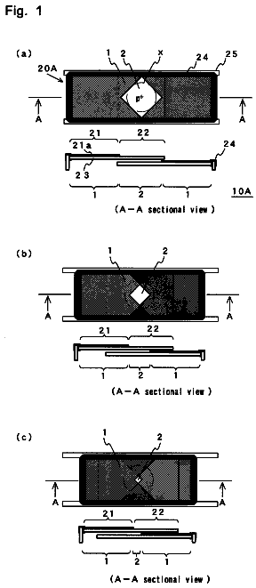
An aperture stop 10A includes a filter area 1 formed on a flat-plate substrate 23, and an aperture area 2 formed inside the filter area 1.
US 8,711,473 B2 · Assignee: Olympus Corporation · Inventors: Hirata; Tadashi
Sheet 1 of 24 from the published document. All sheets in the USPTO PDF
An optical scanning microscope is presented in which the observation magnification does not significantly change even when the working distance of an objective lens is changed. The optical scanning microscope includes an objective optical system that converts the light from a specimen into a substantially collimated light beam, an imaging optical system that forms an image from the collimated light beam, a pupil projection optical system that substantially collimates the light formed into an image, a lateral scanner that angularly deflects the collimated light beam from the pupil projection optical system to laterally scan the area of the specimen to be observed, and a lens driver that drives the imaging optical system and/or the pupil projection optical system along the optical axis direction. The imaging optical system is disposed such that its front focal point is positioned proximate to the back focal point of the objective optical system.
There has been a microscope in which a positive refractive power optical element and a negative refractive power optical element are disposed between a light source and an objective lens and the physical distance between these optical elements is changed to change the working distance of the objective lens (see Japanese Unexamined Patent Application, Publication No. 2005-70477, for example). Also disclosed is a microscope in which an adaptor lens is detachably attached to a finite distance objective lens (see Japanese Unexamined Patent Application, Publication No. 2006-79000, for example). In the microscope, a small-diameter, finite distance objective lens is combined with an adaptor lens, and the working distance of the objective lens is changed by moving the adaptor lens in the optical axis direction. There has also been a microscope having a detachable, finite distance objective lens
1 of 24 drawing sheets so far from the published document, cropped to the drawing. Every sheet is in the USPTO PDF.
What the patent claimed, word for word. All of it is now free to use.
The present invention relates to a focus adjustment unit and an optical scanning microscope.
This application is based on Japanese Patent Applications Nos. 2007-240103 and 2007-240104, the contents of which are incorporated herein by reference.
There has been a microscope in which a positive refractive power optical element and a negative refractive power optical element are disposed between a light source and an objective lens and the physical distance between these optical elements is changed to change the working distance of the objective lens (see Japanese Unexamined Patent Application, Publication No. 2005-70477, for example).
Also disclosed is a microscope in which an adaptor lens is detachably attached to a finite distance objective lens (see Japanese Unexamined Patent Application, Publication No. 2006-79000, for example). In the microscope, a small-diameter, finite distance objective lens is combined with an adaptor lens, and the working distance of the objective lens is changed by moving the adaptor lens in the optical axis direction.
There has also been a microscope having a detachable, finite distance objective lens (see Japanese Unexamined Patent Application, Publication No. 2006-139181, for example). In the microscope, a finite distance objective lens is combined with an imaging lens, and the working distance of the objective lens is changed by moving the imaging lens in the optical axis direction.
The patent publication disclosures about the above microscopes, however, do not describe at all the positional relationship of the objective lens and the imaging lens with the optical system that shifts the focal point, and it is conceivable that moving a lens that is part of the optical system in the optical axis direction in order to change the working distance of the objective lens may disadvantageously change the observation magnification greatly if no consideration is given to the positional relationship of the optical system with the objective lens and the imaging lens.
The invention has been made in view of the above circumstances. An object of the invention is to provide a focus adjustment unit and an optical scanning microscope that does not greatly change the observation magnification even when the working distance of the objective lens is changed.
A first configuration of the invention is an optical scanning microscope including an objective optical system that converts the light from a specimen into a substantially collimated light beam, an imaging optical system that forms an image from the substantially collimated light beam from the objective optical system at a predetermined position, a pupil projection optical system that substantially collimates the light formed into an image by the imaging optical system at the predetermined position, a lateral scanner that angularly deflects the substantially collimated light beam from the pupil projection optical system to laterally scan the location of the specimen to be observed, and a lens driver that drives the imaging optical system or the pupil projection optical system or both in the optical axis direction. Defining the front side as the side where the specimen is located, the imaging optical system is disposed in such a way that the front focal point thereof is positioned in the vicinity of the back focal point of the objective optical system.
According to the first configuration of the invention, driving the imaging optical system or the pupil projection optical system or both in the optical axis direction changes the working distance of the objective lens. In this case, disposing the front focal point of the imaging optical system in the vicinity of the back focal point of the objective optical system can reduce the change in magnification when the imaging optical system or the pupil projection optical system is moved in the optical axis direction.
It is noted that here a substantially collimated light beam not only includes an exactly collimated light beam but also a slightly divergent or convergent light beam.
In the first configuration described above, it is preferable that the lens driver drives the imaging optical system in the optical axis direction, the pupil projection optical system is fixed, and the following equation
is satisfied: |D1a.times..DELTA.s|/(Ftl).sup.2.ltoreq.0.05
where .DELTA.s represents the total distance over which the imaging optical system moves; D1a represents the gap between the back focal point of the objective optical system and the front focal point of the imaging optical system when the imaging optical system moves to a middle position; and Ftl represents the focal length of the imaging optical system.
Such a configuration can reduce the change in magnification when the working distance is changed.
In the first configuration described above, it is preferable that D1a=0.
Such a configuration can completely prevent change in magnification when the working distance is changed.
In the first configuration described above, the lens driver may alternatively drive the pupil projection optical system in the optical axis direction, whereas the imaging optical system may be fixed. In this case, the following equation
may be satisfied: |D1.times..delta.s|/(Ftl).sup.2.ltoreq.0.05
where .delta.s represents the total distance over which the pupil projection optical system moves; D1 represents the gap between the back focal point of the objective optical system and the front focal point of the imaging optical system, and Ftl represents the focal length of the imaging optical system.
In the first configuration described above, it is preferable that D1=0.
Such a configuration can completely prevent change in magnification when the working distance is changed.
In the first configuration described above, the pupil projection optical system or the imaging optical system or both may be moved within a range centered at a position where it becomes an afocal optical system.
Such a configuration can reduce the change in magnification when the working distance is changed.
In the first configuration described above, the lateral scanner may be disposed in the vicinity of the back focal point of the pupil projection optical system.
If this is done, a nearly telecentric optical system (the exit pupil is located at infinity) can be formed on the side toward the specimen.
In the first configuration described above, the optical scanning microscope may further include a light emitter that emits light that illuminates or excites the specimen, a light receiver that receives the light from the specimen, a first collimator optical system that substantially collimates the light from the light emitter, a second collimator optical system that focuses the light from the specimen on the light receiver, a detected light separator that separates the light from the specimen from the light from the light emitter, a scan optical system that includes the lateral scanner, and a pupil position adjuster that moves the scan optical system in the optical axis direction of the pupil projection optical system so that the pupil position coincides with a point in the vicinity of the lateral scanner.
A second configuration of the invention is a focus adjustment unit used in a microscope system including an objective optical system that converts the light from a specimen into a substantially collimated light beam and an imaging optical system that forms an image from the substantially collimated light beam from the objective optical system at a predetermined position, the focus adjustment unit disposed between the objective optical system and the imaging optical system and changing the working distance of the objective optical system. Defining the front side to be the side where the objective optical system is located and the back side to be side where the imaging optical system is located, the focus adjustment unit includes a front-group optical system and a rear-group optical system disposed in this order from the front side, each of the optical systems having a refractive power, and a lens driver that drives the front-group optical system or the rear-group optical system or both in the optical axis direction to change the relative distance between the two optical systems in the optical axis direction. The front-group optical system is disposed in such a way that the front focal point thereof is positioned in the vicinity of the back focal point of the objective optical system.
According to the second configuration of the invention, driving the front-group optical system or the rear-group optical system or both in the optical axis direction changes the working distance of the objective lens. In this case, disposing the front focal point of the front-group optical system in the vicinity of the back focal point of the objective optical system can reduce the change in magnification when the front-group optical system or the rear-group optical system is moved in the optical axis direction.
It is noted, as in the first configuration, that here a substantially collimated light beam not only includes an exact collimated light beam but also a slightly divergent or convergent light beam.
In the second configuration described above, the front-group optical system and the rear-group optical system may be moved within a range centered at a position where the front-group optical system and the rear-group optical system form an afocal optical system. Such a configuration can reduce the change in magnification when the working distance of the objective lens is changed.
The second configuration described above may be such that only the front-group optical system can be moved in the optical axis direction, the rear-group optical system is fixed, and the following equation
is satisfied: |D1a.times..DELTA.s|/(Fla).sup.2.ltoreq.0.05
where .DELTA.s represents the total distance over which the front-group optical system moves; D1a represents the gap between the back focal point of the objective optical system and the front focal point of the front-group optical system when the front-group optical system moves to the middle position of its movement range; and Fla represents the focal length of the front-group optical system.
In the second configuration described above, D1a may be zero.
Such a configuration can greatly reduce the change in magnification when the working distance is changed.
The second configuration described above also may be such that the front-group optical system is fixed, only the rear-group optical system can be moved in the optical axis direction, and the following equation
is satisfied: |D1.times..delta.s|/(Fla).sup.2.ltoreq.0.05
In the equation (9), .delta.s represents the total distance over which the rear-group optical system moves; D1 represents the gap between the back focal point of the imaging optical system and the front focal point of the front-group optical system; and Fla represents the focal length of the front-group optical system.
In the second configuration described above, it is preferable that the front focal point of the front-group optical system coincides with the back focal point of the objective optical system.
Such a configuration can completely prevent the change in magnification when the working distance is changed.
In the second configuration described above, it is preferable that |Fla|>|Flb|.
In such a configuration, the pupil diameter of the objective optical system can be reduced, and the outer dimension of the objective optical system can be reduced accordingly.
In the second configuration described above, the front-group optical system may have a negative focal length.
In such a configuration, the total length of the focus adjustment unit can be reduced.
In the second configuration described above, the back focal point of the objective optical system may be located behind the abutting position of the objective optical system.
In such a configuration, the gap between the front focal point of the front-group optical system and the back focal point of the objective optical system can be reduced, whereby the change in magnification when the working distance is changed can be reduced.
In the second configuration described above, the focus adjustment unit may further include an adjustment mechanism that adjusts the gap between the back focal point of the objective optical system and the front focal point of the front-group optical system.
In such a configuration, the adjustment mechanism can make adjustment in such a way that the change in magnification is very small and nearly linear even when the position of the back focal point of the objective optical system differs from the abutting position of the objective optical system.
In the second configuration described above, the back focal point of the rear-group optical system may be located in the vicinity of the front focal point of the imaging optical system.
In the second configuration described above, the focus adjustment unit may further include an adjustment mechanism that adjusts the gap between the back focal point of the rear-group optical system and the front focal point of the imaging optical system.
In such a configuration, a nearly telecentric optical system (the exit pupil is located at infinity) can be formed at the image plane.
A third configuration of the invention is an optical scanning microscope including an objective optical system that focuses the light from a specimen, an imaging optical system that forms an image from the light focused by the objective optical system at a predetermined position, any focus adjustment unit according to the second configuration, a pupil projection optical system which is disposed behind the imaging lens and which converts the image of the specimen formed by the imaging lens at the predetermined position into a collimated light beam, a scan optical system including a lateral scanner that laterally scans the light substantially collimated by the pupil projection optical system, a light emitter that emits light that illuminates or excites the specimen, a light receiver that receives the light from the specimen, a first collimator optical system that substantially collimates the light from the light emitter, a second collimator optical system that focuses the light from the specimen at the light receiver, a detected light separator that separates the light from the specimen from the light from the light emitter, and a pupil position adjuster that moves the scan optical system in the optical axis direction of the pupil projection optical system so that the pupil position coincides with a point in the vicinity of the lateral scanner.
According to the invention, the working distance of the objective lens can be changed without changing the observation magnification by much.
FIG. 1 is an overall configuration diagram showing a laser scanning microscope according to a first embodiment of the invention;
FIG. 2 explains the principle of how the working distance changes when optical systems are displaced in the laser scanning microscope shown in FIG. 1 and shows the optical systems arranged in their reference positions;
FIG. 3 shows a state where the optical systems are displaced from the reference positions shown in FIG. 2;
FIG. 4 explains the change in working distance when only an imaging optical system is displaced in the laser scanning microscope shown in FIG. 1;
FIG. 5 is a graph plotting the amount of change in working distance against the displacement of the imaging optical system in the laser scanning microscope shown in FIG. 4;
FIG. 6 is a graph plotting the lateral magnification against the displacement of the imaging optical system in the laser scanning microscope shown in FIG. 4;
FIG. 7 is an overall configuration diagram showing a laser scanning microscope according to a second embodiment of the invention;
FIG. 8 explains the change in working distance when only an pupil projection optical system is displaced in the laser scanning microscope shown in FIG. 7;
FIG. 9 is a graph plotting the amount of change in working distance against the displacement of the pupil projection optical system in the laser scanning microscope shown in FIG. 8;
FIG. 10 is a graph plotting the lateral magnification against the displacement of the pupil projection optical system in the laser scanning microscope shown in FIG. 8;
FIG. 11 is an overall configuration diagram showing a laser scanning microscope according to a third embodiment of the invention;
FIG. 12 is a graph plotting the displacement of the position of an exit pupil against the displacement of an imaging optical system or a pupil projection optical system in the laser scanning microscope shown in FIG. 11;
FIG. 13 is an overall configuration diagram showing a modification of the laser scanning microscope shown in FIG. 11, the laser scanning microscope including a imaging optical system, pupil projection optical system, and scan optical system which are movable;
FIG. 14 is an overall configuration diagram showing a laser scanning microscope according to a fourth embodiment of the invention;
FIG. 15 shows a focus adjustment unit (Example 3) according to the fourth embodiment used in the laser scanning microscope shown in FIG. 14;
FIG. 16 shows a state where the front focal point of a front-group optical system shown in the focus adjustment unit coincides with the back focal point of an objective lens shown in FIG. 15;
FIG. 17 explains the principle of the focus adjustment unit according to the fourth embodiment used in the laser scanning microscope shown in FIG. 14;
FIG. 18 shows graphs illustrating the amount of change in working distance of the objective lens versus the displacement of the front-group optical system in the focus adjustment unit when the optical systems are located in the positions shown in FIGS. 15 and 16;
FIG. 19 shows graphs illustrating the lateral magnification versus the displacement of the front-group optical system in the focus adjustment unit when the optical systems are located in the positions shown in FIGS. 15 and 16;
FIG. 20 shows a focus adjustment unit according to Example 4 used in the laser scanning microscope shown in FIG. 14;
FIG. 21 shows a state where the front focal point of a front-group optical system in the focus adjustment unit shown in FIG. 20 coincides with the back focal point of an objective lens;
FIG. 22 is a graph plotting the amount of change in working distance of the objective lens against the displacement of a rear-group optical system in the focus adjustment unit in FIGS. 20 and 21;
FIG. 23 is a graph plotting the lateral magnification against the displacement of the rear-group optical system in the focus adjustment unit in FIGS. 20 and 21;
FIG. 24 shows a focus adjustment unit according to Example 5 used in the laser scanning microscope shown in FIG. 14;
FIG. 25 shows a modification of the focus adjustment unit according to Example 5 used in the laser scanning microscope shown in FIG. 14;
FIG. 26 is a graph plotting the amount of change in working distance of the objective lens against the displacement of a rear-group optical system in the focus adjustment unit in FIGS. 24 and 25;
FIG. 27 is a graph plotting the lateral magnification against the displacement of the rear-group optical system in the focus adjustment unit in FIGS. 24 and 25;
FIG. 28 shows a focus adjustment unit according to Example 6 used in the laser scanning microscope shown in FIG. 14;
FIG. 29 shows a state where the front focal point of a front-group optical system in the focus adjustment unit shown in FIG. 28 coincides with the back focal point of an objective lens;
FIG. 30 shows a case where the position of the focus adjustment unit shown in FIG. 20 can be adjusted in the forward and backward directions; and
FIG. 31 shows a microscope body of a modification of the laser scanning microscope shown in FIG. 14, the modification of the laser scanning microscope including a scan optical system movable in the optical axis direction.
A: Specimen 1, 30, 40: Laser scanning microscope (optical scanning microscope) 4a: Radiation exit end (light output portion) 6: Collimator optical system (first collimator optical system) 7: Dichroic mirror (detected light separator) 8: Closely set galvanometric mirrors (lateral scanners) 9: Pupil projection optical system 10: Imaging optical system 11: Objective optical system 12, 12': Lens driver 13: Coupling optical system (second collimator optical system) 14a: Radiation entrance end (light receiver portion) 41: Scan optical system 42: Pupil position adjuster Ga: Front-group optical system Gb: Rear-group optical system 101: Focus adjustment unit 102: Laser scanning microscope (microscope system) 105: Optical fiber (light exit) 106: Collimator optical system (first collimator optical system) 108: Dichroic mirror (detected light separator) 109: Adjacent galvanometric mirrors (lateral scanners) 110: Pupil projection optical system 111: Imaging optical system 112: Objective optical system 113: Coupling optical system (second collimator optical system) 114: Optical fiber (light receiver) 118: Lens driver 126: Scan optical system 127: Pupil position adjuster
A laser scanning microscope (optical scanning microscope) 1 according to a first embodiment of the invention will be described below with reference to FIGS. 1 to 6.
The laser scanning microscope 1 according to the present embodiment includes a laser light source 2 that emits laser light, a coupling optical system 3 that focuses the laser light from the laser light source 2, an optical fiber 4 that guides the laser light focused by the coupling optical system 3, a microscope body 5 that is connected to the laser light source via the optical fiber 4, a optical detection system 15, a controller 16 that controls the above components, and a display device (not shown) that displays a fluorescent light or reflected light image detected by the optical detection system 15.
The microscope body 5 includes a collimator optical system 6 that converts the laser light that has exited from the optical fiber 4 into a substantially collimated light beam, a dichroic mirror 7 that deflects the laser light substantially collimated by the collimator optical system 6, adjacent galvanometric mirrors 8 that scan the laser light deflected off the dichroic mirror 7 in two dimensions, a pupil projection optical system 9 that focuses the laser light scanned by the adjacent galvanometric mirrors 8, an imaging optical system 10 and an objective optical system 11 that focus the focused light on a specimen A, and a lens driver 12 that drives the imaging optical system 10 in the optical axis direction.
The microscope body 5 includes the dichroic mirror 7 that transmits fluorescent light or reflected light that has returned from the specimen A via the objective optical system 11, the imaging optical system 10, the pupil projection optical system 9, and the adjacent galvanometric mirrors 8, and further includes a coupling optical system 13 that focuses the transmitted light onto an optical fiber 14, and an optical fiber 14 that guides the fluorescent light or reflected light that has returned from the specimen A and has been focused by the coupling optical system 13.
The microscope body 5 is not only disposed so as to be movable in three mutually orthogonal axial (XYZ) directions and also rotatable around these axes so that the position and the angle of the tip of the objective optical system 11 can be arbitrarily adjusted.
The adjacent galvanometric mirrors 8 are designed to scan an area to be observed in directions substantially perpendicular to the optical axis of the objective optical system 11. The intensity distribution of the light from the portion of the specimen A that corresponds to the present deflection angle of the adjacent galvanometric mirrors 8 is displayed on the display.
The objective optical system 11 is designed to prevent an image to be observed from moving even when the specimen A breaths and beats by keeping the tip of the objective optical system 11 in tight contact with the specimen A.
In such a configuration, it is desirable to satisfy the condition expressed by the following equation (1): |D1a.times..DELTA.s|/(Ftl).sup.2.ltoreq.0.05
where .DELTA.s represents the total distance over which the imaging optical system 10 moves, D1a represents the gap between the back focal point of the objective optical system 11 and the front focal point of the imaging optical system 10 when the imaging optical system 10 moves to the middle position of its movement range. Ftl represents the focal length of the imaging optical system 10.
The optical detection system 15 includes a collimator optical system 17 that substantially collimates the fluorescent or reflected light guided through the optical fiber 14, a plurality of beam-splitting dichroic mirrors 18 for respective wavelengths, a mirror 19, barrier filters 20, collector lenses 21, and photodetectors 22. In FIG. 1, reference numeral 23 denotes a dichroic mirror, and reference numeral 24 denotes a mirror.
The operation of the thus configured laser scanning microscope 1 according to the present embodiment will be described below.
To observe the specimen A using the laser scanning microscope 1 according to the present embodiment, the tip of the objective optical system 11 is first brought in tight contact with the specimen A. The laser light is then introduced into the microscope body 5 from the laser light source 2 through the optical fiber 4 and deflected off the dichroic mirror 7. The laser light is scanned by the adjacent galvanometric mirrors 8 in two dimensions, and then focused on the specimen A through the pupil projection optical system 9, the imaging optical system 10, and the objective optical system 11.
In the specimen A irradiated with the laser light, fluorescent substances are excited and produce fluorescent light. The objective optical system 11 converts the produced fluorescent light into a collimated or slightly divergent or convergent light beam. The light is formed into an image by the imaging optical system 10 and substantially collimated by the pupil projection optical system 9. The light then reflects off the adjacent galvanometric mirrors 8 and passes through the dichroic mirror 7 and is focused by the coupling optical system 13 into the end of the optical fiber 14. The light is guided through the optical fiber 14 and then detected by the optical detection system 15.
In this case, for example, as shown in FIG. 4, when the lens driver 12 moves the imaging optical system 10 in the optical axis direction, the working distance of the objective optical system 11 (the distance from the tip of the objective optical system to the focal point) changes.
Therefore, a portion of the specimen A at an arbitrary depth can be imaged without moving the objective optical system 11. Further, a three-dimensional image of the specimen A can be acquired from a plurality of images captured by moving the imaging optical system 10.
The principle of the invention will be described with reference to FIGS. 2 and 3.
FIG. 2 shows reference positions of the optical systems described above, and FIG. 3 shows a state where the optical systems move from the reference positions.
The reference positions are set in such a way that the imaging optical system 10 and the pupil projection optical system 9 form an afocal optical system (that is, the back focal point of the imaging optical system 10 coincides with the front focal point of the pupil projection optical system 9), and that the objective optical system 11 is positioned so that D1 is the gap between the back focal point of the objective optical system 11 and the front focal point of the imaging optical system 10.
In FIGS. 2 and 3, points P1 to P8 are defined as follows:
P1: Front focal point of objective optical system 11
P2: Position of objective optical system 11
P3: Back focal point of objective optical system 11
P4: Front focal point of imaging optical system 10
P5: Position of imaging optical system 10
P6: Back focal point of imaging optical system 10 and front focal point of pupil projection optical system 9
P7: Position of pupil projection optical system 9
P8: Back focal point of pupil projection optical system 9
To make the light beam behind the pupil projection optical system 9 substantially collimated, the following equation should be satisfied: Zwd=n(.DELTA.-.delta.)(Fob/Ftl).sup.2/(1+A)
When the collimated light beam behind the pupil projection optical system 9 is inclined to the optical axis by an angle .theta.pl, the ratio of the angle .theta.pl to the height Yob perpendicular to the optical axis of the corresponding beam at the focal point by the specimen A, that is, (.theta.pl/Yob), is given as follows: (.theta.pl/Yob)=M/Fpl
where M=-(Ftl/Fpl)(1+A)
A=(D1+A)(.DELTA.-.delta.)/Ftl.sup.2
Zwd is the amount of change in working distance of objective optical system 11 from reference position P1 .DELTA. is the amount of displacement of imaging optical system 10 from reference position P5 .delta. is the amount of displacement of pupil projection optical system 9 from reference position P7 n: Refractive index of the specimen Fob: Focal length of objective optical system 11 Ftl: Focal length of imaging optical system 10 Fpl: Focal length of pupil projection optical system 9 M: Lateral magnification of the image of the specimen formed by the objective optical system 11 and imaging optical system 10 .theta.pl: Angle of collimated light behind pupil projection optical system 9 with respect to optical axis when light ray height of object is Yob (the angle .theta.pl corresponds to half value of scan angle of adjacent galvanometric mirrors 8)
The position of the exit pupil Zp (when the entrance pupil on the objective side is located at infinity) is given by the following equation: Zp={.delta.-(Fpl/Ftl).sup.2.times.(D1+.DELTA.)/(1+A)}
Therefore, in the laser scanning microscope according to the present embodiment, as shown in FIG. 4, since the pupil projection optical system 9 is fixed and the lens driver 12 drives the imaging optical system 10 in the optical axis direction, .delta.=0 and the above equations
to
reduce to the following relationship: Zwd=n.times..DELTA.(Fob/Ftl).sup.2/(1+Atl) (3') Here, (.theta.pl/Yob)=Mtl/Fpl (4') but also Mtl=-(Ftl/Fob)(1+Atl) (5') Atl=(D1+.DELTA.).times..DELTA./Ftl.sup.2 (6')
The equation (3') shows that the range over which .DELTA. shifts largely determines the range over which Zwd changes.
The optical systems are desirably arranged in such a way that the range over which the imaging optical system moves is the vicinity of the point .DELTA.=0 (the position where the pupil optical system and the imaging optical system form an afocal optical system) and the back focal point of the objective optical system is located in the vicinity of the front focal point of the imaging optical system, that is, D1 is small.
In such an arrangement, since the equation (6') shows that the amount of change in Atl with change in .DELTA. is small when .DELTA. is in the vicinity of 0, moving the imaging optical system (changing .DELTA.) will not greatly change the lateral magnification Mtl or the ratio of the light ray angle to the object height (.theta.pl/Yob).
Specifically, D1a is desirably set to satisfy equation (1). In such a condition, the changes in Atl and the lateral magnification Mtl can be reduced to approximately 5% or smaller.
In FIG. 5, the horizontal axis represents .DELTA. (displacement of the imaging optical system) and the vertical axis represents Zwd (change in the working distance WD), and in FIG. 6, the horizontal axis represents .DELTA. and the vertical axis represents (.theta.pl/Yob), that is, a quantity proportional to the lateral magnification M.
For example, the solid lines (A) in FIGS. 5 and 6 show the results under the following conditions: Fob=9 mm, Ftl=50 mm, Fpl=12 mm, .DELTA.: -1.5 mm to +1.5 mm, that is, .DELTA.s=3 mm, and D1a=15 mm.
The above values are substituted into the equation (1), and the following equation is derived: |D1a.times..DELTA.s|/(Ftl).sup.2=0.018.ltoreq.0.05
The equation
is thus satisfied.
The change in Atl is only 0.0018 throughout the range over which the imaging optical system can move. When the equation
is thus satisfied, the change in Atl in (6') becomes small throughout the range over which the imaging lens moves, whereby the change in the lateral magnification Mtl in (5') and the change in the ratio of the light ray angle to the object height (.theta.pl/Yob) in (4') become sufficiently small for satisfactory actual operation even when the working distance WD changes.
Further, when one wishes to greatly reduce the change in lateral magnification, one can simply set D1a to zero. The broken lines (B) in FIGS. 5 and 6 show the results where D1=0 and Fob, Ftl, Fpl, and .DELTA. are the same as the above values.
In this case, since the slope of Atl with respect to .DELTA. becomes zero in the vicinity of the point .DELTA.=0, the change in lateral magnification is very small. In the present embodiment, the change in Atl is 0.0009 over the whole range.
A laser scanning microscope 30 according to a second embodiment of the invention will be described below with reference to FIGS. 7 to 10.
In the description of the present embodiment, those components common to the components of the laser scanning microscope 1 according to the first embodiment described above have the same reference numerals, and no description thereof will be made.
In the laser scanning microscope 30 according to the present embodiment, the lens driver 12 drives the pupil projection optical system 9 in the optical axis direction as shown in FIG. 7, which differs from the laser scanning microscope 1 according to the first embodiment where the lens driver 12 drives the imaging optical system 10 in the optical axis direction.
Since driving the pupil projection optical system 9 in the optical axis direction changes the working distance, a portion of the specimen A at an arbitrary depth can be imaged.
Therefore, in the laser scanning microscope 30 according to the present embodiment, as shown in FIG. 8, since the imaging optical system 10 is fixed and the lens driver 12 drives the pupil projection optical system 9 in the optical axis direction, .DELTA.=0 and the above equations
to
establish the following relationship: Zwd=.times.-n.times..delta.(Fob/Ftl).sup.2/(1+Apl) (3'') Here, (.theta.pl/Yob)=Mpl/Fpl (4'') but Mpl=-(Ftl/Fob)(1+Apl) (5'') Apl=-.delta..times.D1/Ftl.sup.2 (6'')
The equation (3'') shows that the range over which .delta. shifts largely determines the range over which Zwd changes. The back focal point of the objective optical system 11 is desirably located in the vicinity of the front focal point of the imaging optical system 10; that is, so that D1 is small. When D1 is small, moving the pupil projection optical system (changing .delta.) will not greatly change the lateral magnification Mpl or the ratio of the light ray angle to the object height (.theta.pl/Yob).
The equation (6'') shows that the change in Apl is proportional to D1 and .delta..
Since the range over which .delta. shifts largely determines the range over which Zwd changes, the range of .delta. does not change greatly. Therefore, D1 largely determines the change in Mpl.
Specifically, the following equation involving the total amount of movement .delta.s of the pupil projection lens is preferably satisfied: D1.times..DELTA.s|/Ftl.sup.2.ltoreq.0.05
The change in Apl can be reduced to 0.05 or smaller in such case.
In FIG. 9, the horizontal axis represents .delta. (displacement of the pupil projection optical system) and the vertical axis represents Zwd (change in the working distance WD), and in FIG. 10, the horizontal axis represents .delta. and the vertical axis represents (.theta.pl/Yob), that is, a quantity proportional to the lateral magnification.
For example, the solid lines (A) in FIGS. 9 and 10 show the results under the following conditions: Fob=9 mm, Ftl=50 mm, Fpl=12 mm, .delta.: -1.5 mm to +1.5 mm, that is, .delta.s=3 mm, and D1a=15 mm.
When the above values are substituted into the condition (2), the following condition is derived: |D1.times..delta.s|/Ftl.sup.2=0.018.ltoreq.0.05 The equation
is thus satisfied.
The change in Apl is only 0.0018. When the equation
is thus satisfied, the change in Apl in (6'') becomes small, whereby the change in the lateral magnification Mpl in (5'') and the change in the ratio of the light ray angle to the object height (.theta.pl/Yob) in (4'') become sufficiently small for satisfactory actual operation even when the working distance WD changes.
Further, when one wishes to greatly reduce the change in lateral magnification, one can simply set D1 to zero. The broken lines (B) in FIGS. 9 and 10 show the results obtained when D1=0 and Fob, Ftl, Fpl, and .DELTA. are the same as the above values.
In this case, since Apl is always zero, regardless of the value of .delta., the lateral magnification will not change at all.
A laser scanning microscope 40 according to a third embodiment of the invention will be described below with reference to FIGS. 11 and 12.
In the description of the present embodiment, those components common to the components of the laser scanning microscope 1 according to the first embodiment described above have the same reference numerals, and no description thereof will be made.
The laser scanning microscope 40 according to the present embodiment is similar to the laser scanning microscope 30 according to the second embodiment where the lens driver 12 drives the pupil projection optical system 9 in the optical axis direction, but in addition includes a scan optical system 41 including a radiation exit end (light output portion) 4a of the optical fiber 4, a radiation entrance end (light receiving portion) 14a of the optical fiber 14, the collimator optical system 6, the coupling optical system 13, the dichroic mirror 7, and the adjacent galvanometric mirrors 8, and also a pupil position adjuster 42 that integrally moves the scan optical system 41 in the optical axis direction of the pupil projection optical system 9, as shown in FIG. 11.
Integrally moving the scan optical system 41 in the optical axis direction of the pupil projection optical system 9 by actuating the pupil position adjuster 42 allows the pupil position to coincide with the adjacent galvanometric mirrors 8.
The adjustment of the position of the exit pupil Zp by using the pupil position adjuster 42 may be carried out in accordance with the equation (7). It is noted that the point Zp=0 coincides with the position of the back focal point of the pupil projection optical system 9 located in the reference position shown in FIG. 2.
When the imaging optical system 10 is fixed and the pupil projection optical system 9 is moved in the optical axis direction as shown in FIG. 11, the equation
is modified as follows: Zp={.delta.-(Fpl/Ftl).sup.2.times.D1/(1+A)}
When the equation
or
is satisfied, 1>>A and hence the following equation is satisfied: Zp=.delta.-(Fpl/Ftl).sup.2.times.D1 and the displacement .delta. of the pupil projection optical system 9 is a linear function of the position of the exit pupil Zp, changing approximately the same amount as .delta. does, as shown in FIG. 12.
While the present embodiment has been described with reference to the case where the lens driver 12 drives the pupil projection optical system 9, alternatively the pupil projection optical system 9 can be fixed and the imaging optical system 10 can be moved in the optical axis direction. In this case, the equation
is modified as follows: Zp=-(Fpl/Ftl).sub.2.times.(D1+.DELTA.)
The description continues in the full USPTO document.
About 6,406 words. The USPTO PDF has it with every drawing.
Fees are due 3.5, 7.5 and 11.5 years after grant. This patent expired on April 29, 2026, so the fee marked "not paid" was the one that went unpaid.
FOCUS ADJUSTMENT UNIT AND OPTICAL SCANNING MICROSCOPE
Filed Sep 2008 · published Mar 2009Focus adjustment unit and optical scanning microscope
Filed Sep 2008 · granted Apr 2014Earlier publications, parents and continuations. None of them can still be enforced, or this patent would not be listed.
Prior art cited by the examiner or applicant. Useful when you check your own idea for novelty.
Everything on this page comes from the documents linked above.


