Cross-reference to related application
The present application claims priority from Japanese Patent Application No. 2011-199828 filed Sep. 13, 2011.
Background
1. Technical field
This disclosure relates to an extreme ultraviolet (EUV) light generation apparatus.
2. Related art
In recent years, semiconductor production processes have become capable of producing semiconductor devices with increasingly fine feature sizes, as photolithography has been making rapid progress toward finer fabrication. In the next generation of semiconductor production processes, microfabrication with feature sizes at 60 nm to 45 nm, and further, microfabrication with feature sizes of 32 nm or less will be required. In order to meet the demand for microfabrication with feature sizes of 32 nm or less, for example, an exposure apparatus is needed in which a system for generating EUV light at a wavelength of approximately 13 nm is combined with a reduced projection reflective optical system.
Three kinds of systems for generating EUV light are known in general, which include a Laser Produced Plasma (LPP) type system in which plasma is generated by irradiating a target material with a laser beam, a Discharge Produced Plasma (DPP) type system in which plasma is generated by electric discharge, and a Synchrotron Radiation (SR) type system in which orbital radiation is used to generate plasma.
Summary
An apparatus according to one aspect of this disclosure, which may be used with an external laser apparatus, for generating extreme ultraviolet light may include: a target storage unit configured to store a target material thereinside; a nozzle unit having a through-hole through which the target material stored inside the target storage unit is outputted, the through-hole formed therein being in fluid communication with the interior of the storage unit; an electrode facing the nozzle unit, the electrode having a through-hole formed therein; a target detector configured to detect a target formed of the target material and output a detection signal; a chamber in which extreme ultraviolet light is generated; a direct current voltage adjuster configured to apply a direct current between the target material and the electrode, the direct current voltage adjuster being capable of adjusting the direct current; a pressure adjuster configured to apply a pressure to the target material through gas, the pressure adjuster being capable of adjusting the pressure; and a controller configured to control at least one of the direct current voltage adjuster and the pressure adjuster based on the detection signal from the target detector.
Brief description of the drawings
Hereinafter, selected embodiments of this disclosure will be described with reference to the accompanying drawings.
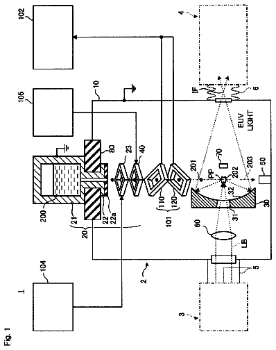
FIG. 1 schematically illustrates the configuration of an exemplary LPP type EUV light generation system.
FIG. 2 is a partial sectional view illustrating an example of the configuration of an EUV light generation system according to an embodiment of this disclosure.
FIG. 3A is a sectional view illustrating a target supply unit shown in FIG. 2 and peripheral components thereof.
FIG. 3B is an enlarged sectional view illustrating a part of the target supply unit shown in FIG. 3A.
FIG. 4 is a flowchart showing an example of the operation of the EUV light generation system shown in FIG. 2.
FIG. 5A is a flowchart showing an exemplary target detection subroutine when a generation frequency of targets is to be controlled.
FIG. 5B is a flowchart showing an exemplary target control subroutine when a generation frequency of targets is to be controlled.
FIG. 6A is a flowchart showing an exemplary target detection subroutine when a diameter of a target is to be controlled.
FIG. 6B is a flowchart showing an exemplary target control subroutine when a diameter of a target is to be controlled.
FIG. 7A is a partial sectional view illustrating an EUV light generation system which includes an optical target detector.
FIG. 7B is a sectional view of the EUV light generation system shown in FIG. 7A, taken along VIIB-VIIB plane.
FIG. 7C is a partial sectional view illustrating an EUV light generation system which includes an optical target detector.
FIG. 7D is a sectional view of the EUV light generation system shown in FIG. 7C, taken along VIID-VIID plane.
FIG. 8 illustrates a part of an EUV light generation system which includes an magnetic circuit target detector.
FIG. 9A is a partial sectional view illustrating a modification of the target supply unit shown in FIG. 3A and peripheral components thereof.
FIG. 9B is an enlarged sectional view illustrating a part of the target supply unit shown in FIG. 9A.
FIG. 10 illustrates an example of the configuration of a target sensor used to detect a charged target.
Description of preferred embodiments
Hereinafter, selected embodiments of this disclosure will be described in detail with reference to the accompanying drawings. The embodiments to be described below are merely illustrative in nature and do not limit the scope of this disclosure. Further, the configuration(s) and operation(s) described in each embodiment are not all essential in implementing this disclosure. Note that like elements are referenced by like reference numerals and characters, and duplicate descriptions thereof will be omitted herein.
Contents
1. Overview
2. Overview of EUV Light Generation System
2.1 Configuration
2.2 Operation
3. EUV Light Generation System Including Electrostatic-Pull-Out Type Target Supply Unit
3.1 Configuration
3.2 Operation
3.3 Effect
4. Electrostatic-Pull-Out Type Target Supply Unit
4.1 Configuration
4.2 Operation
5. Operation Examples of EUV Light Generation System
6. Variations of Target Detector
6.1 Optical Target Detector: First Variation
6.2 Optical Target Detector: Second Variation
6.3 Magnetic Circuit Target Detector
7. Variation of Target Supply Unit
7.1 Configuration
7.2 Operation
7.3 Effect
8. Supplementary Description
8.1 Detection of Charged Target through Magnetic Circuit
1. Overview
In an LPP type EUV light generation system used with an exposure apparatus, a target material outputted from a target supply unit in the form of droplets may be irradiated with a pulse laser beam to be turned into plasma, and EUV light emitted from the plasma may be outputted to the exposure apparatus. In order to stabilize the energy of the outputted EUV light, a variation in the size of the droplet of the target material outputted from the target supply unit or a variation in the position of the target in a plasma generation region may preferably be small.
2. Overview of EUV Light Generation System
2.1 Configuration
FIG. 1 schematically illustrates the configuration of an exemplary LPP type EUV light generation system. An EUV light generation apparatus 1 may be used with at least one laser apparatus 3. Hereinafter, a system that includes the EUV light generation apparatus 1 and the laser apparatus 3 may be referred to as an EUV light generation system 11. As illustrated in FIG. 1 and described in detail below, the EUV light generation system 11 may include a chamber 2, a target supply unit 26, and so forth. The chamber 2 may be sealed airtight. The target supply unit 26 may be mounted to the chamber 2 to penetrate a wall of the chamber 2. A target material to be supplied by the target supply unit 26 may include, but is not limited to, tin, terbium, gadolinium, lithium, xenon, or any combination thereof.
The chamber 2 may have at least one through-hole formed in its wall, and a pulse laser beam 32 may travel through the through-hole into the chamber 2. Alternatively, the chamber 2 may be provided with a window 21, through which the pulse laser beam 32 may travel into the chamber 2. An EUV collector mirror 23 having a spheroidal surface may be provided inside the chamber 2, for example. The EUV collector mirror 23 may have a multi-layered reflective film formed on the spheroidal surface thereof. The reflective film may include a molybdenum layer and a silicon layer being laminated alternately. The EUV collector mirror 23 may have a first focus and a second focus, and preferably be positioned such that the first focus lies in a plasma generation region 25 and the second focus lies in an intermediate focus (IF) region 292 defined by the specification of an external apparatus, such as an exposure apparatus 6. The EUV collector mirror 23 may have a through-hole 24 formed at the center thereof, and a pulse laser beam 33 may travel through the through-hole 24 toward the plasma generation region 25.
The EUV light generation system 11 may further include an EUV light generation controller 5 and a target sensor 4. The target sensor 4 may have an imaging function and detect at least one of the presence, the trajectory, and the position of a target 27.
Further, the EUV light generation system 11 may include a connection part 29 that allows the interior of the chamber 2 to be in communication with the interior of the exposure apparatus 6. A wall 291 having an aperture may be provided inside the connection part 29, and the wall 291 may be positioned such that the second focus of the EUV collector mirror 23 lies in the aperture formed in the wall 291.
The EUV light generation system 11 may also include a laser beam direction control unit 34, a laser beam focusing mirror 22, and a target collector 28 for collecting targets 27. The laser beam direction control unit 34 may include an optical element for defining the direction into which the pulse laser beam 32 travels and an actuator for adjusting the position and the orientation or posture of the optical element.
2.2 Operation
With continued reference to FIG. 1, a pulse laser beam 31 outputted from the laser apparatus 3 may pass through the laser beam direction control unit 34 and be outputted therefrom as a pulse laser beam 32 after having its direction optionally adjusted. The pulse laser beam 32 may travel through the window 21 and enter the chamber 2. The pulse laser beam 32 may travel inside the chamber 2 along at least one beam path, be reflected by the laser beam focusing mirror 22, and strike at least one target 27 as a pulse laser beam 33.
The target supply unit 26 may be configured to output the target(s) 27 toward the plasma generation region 25 inside the chamber 2. The target 27 may be irradiated with at least one pulse of the pulse laser beam 33. Upon being irradiated with the pulse laser beam 33, the target 27 may be turned into plasma, and rays of light including EUV light 251 may be emitted from the plasma. The EUV light 251 may be reflected selectively by the EUV collector mirror 23. EUV light 252 reflected by the EUV collector mirror 23 may travel through the intermediate focus region 292 and be outputted to the exposure apparatus 6. The target 27 may be irradiated with multiple pulses included in the pulse laser beam 33.
The EUV light generation controller 5 may be configured to integrally control the EUV light generation system 11. The EUV light generation controller 5 may be configured to process image data of the target 27 captured by the target sensor 4. Further, the EUV light generation controller 5 may be configured to control at least one of the timing at which the target 27 is outputted and the direction into which the target 27 is outputted. Furthermore, the EUV light generation controller 5 may be configured to control at least one of the timing at which the laser apparatus 3 oscillates, the direction in which the pulse laser beam 32 travels, and the position at which the pulse laser beam 33 is focused. It will be appreciated that the various controls mentioned above are merely examples, and other controls may be added as necessary.
3. EUV Light Generation System Including Electrostatic-Pull-Out Type Target Supply Unit
3.1 Configuration
FIG. 2 is a partial sectional view illustrating an example of the configuration of an EUV light generation system according to an embodiment of this disclosure. As shown in FIG. 2, a laser beam focusing optical system 22a, the EUV collector mirror 23, the target collector 28, an EUV collector mirror mount 41, plates 42 and 43, a beam dump 44, and a beam dump support member 45 may be provided inside the chamber 2.
The chamber 2 may include a member, such as an electrically conductive member, formed of a highly electrically conductive material, for example, a metal. The chamber 2 may further include an electrically non-conductive member. In that case, the wall of the chamber 2 may, for example, be constituted by the electrically conductive member, and the electrically non-conductive member(s) may be provided inside the chamber 2. The electrically conductive member such as the wall of the chamber 2 may be connected electrically to the reference potential (0 V) of a DC voltage adjuster 55, or may further be grounded.
The plate 42 may be fixed to the chamber 2, and the plate 43 may be fixed to the plate 42. The EUV collector mirror 23 may be held by the EUV collector mirror mount 41 such that the posture and/or the orientation of the EUV collector mirror 23 are/is adjustable. The EUV collector mirror mount 41 may be fixed to the plate 42.
The laser beam focusing optical system 22a may include an off-axis paraboloidal mirror 221 and a flat mirror 222. The off-axis paraboloidal mirror 221 and the flat mirror 222 may be mounted on the plate 43 through respective mirror holders such that a laser beam reflected sequentially by these mirrors 221 and 222 is focused in the plasma generation region 25.
The beam dump 44 may be fixed to the chamber 2 through the beam dump support member 45 such that the beam dump 44 is positioned on an extension of the beam path of the laser beam. The target collector 28 may be provided in the chamber 2 downstream from the plasma generation region 25 in the direction in which targets 27 travel.
The chamber 2 may further include the window 21, the target supply unit 26 of an electrostatic-pull-out type, and a target detector 46. The target supply unit 26 may include a reservoir or target storage unit 61, a nozzle unit 62, and an electrode 66. Electrically conductive metal or the like may be used as the target material. In some embodiments disclosed in this specification, tin (Sn), whose melting point is 232.degree. C., may be used as the target material.
The reservoir 61 may store tin serving as the target material. The nozzle unit 62 may have a through-hole 62a, as shown in FIG. 3B, formed therein, which is in communication with the interior of the reservoir 61. The target material stored in the reservoir 61 may be outputted through the through-hole 62a formed in the nozzle unit 62. The electrode 66 may be provided to face the nozzle unit 62. When a DC voltage is applied between the electrode 66 and the target material, electrostatic force may act on the target material, and the target material may project through the through-hole 62a formed in the nozzle unit 62 and be eventually separated into droplets to form the targets 27. The details of the target supply unit 26 will be given later.
The target detector 46 may be configured to detect a target 27 outputted from the target supply unit 26 passing through a predetermined region. Upon detecting the target 27, the target detector 46 may output a target detection signal to a target control device 52.
A beam delivery unit 34a and the EUV light generation controller 5 may be provided outside the chamber 2. The beam delivery unit 34a may include high reflection mirrors 341 and 342, holders for the respective mirrors 341 and 342, and a housing in which the mirrors 341 and 342 are disposed. The EUV light generation controller 5 may include an EUV light generation control device 51, the target control device 52, a pressure adjuster 53, an inert gas cylinder 54, the DC voltage adjuster 55, a trigger signal generation circuit 56, and a timer 57.
The pressure adjuster 53 may be configured to adjust the pressure of gas to be applied to the target material stored inside the reservoir 61. As the pressure of gas applied to the target material is adjusted, a generation frequency of the targets 27 may be adjusted. For example, the pressure adjuster 53 may be configured to control the pressure of an inert gas supplied from the inert gas cylinder 54.
The DC voltage adjuster 55 may be configured to control a DC voltage to be applied between the electrode 66 and the target material. As the DC voltage is controlled, the size of the target 27 outputted from the target supply unit 26 may be adjusted. For example, the DC voltage adjuster 55 may include a switching power supply circuit configured to first generate a DC voltage by rectifying an AC voltage supplied from a commercial power supply and then generate a desired DC voltage through DC/DC-conversion of the generated DC voltage.
A target detection signal outputted from the target detector 46 may be inputted to the trigger signal generation circuit 56 through the target control device 52. The trigger signal generation circuit 56 may be configured to generate a trigger signal having a desired delay time with respect to the inputted target detection signal, and output this trigger signal to the laser apparatus 3. The trigger signal may serve to define a timing at which a laser beam is outputted. With this configuration, the target 27 may be irradiated precisely with the laser beam outputted from the laser apparatus 3 in the plasma generation region 25.
The timer 57 may be configured to count clock signals by a quartz resonator or the like to generate a timed value, and output the timed value to the target control device 52. The timed value may be used to calculate a generation frequency of the targets 27.
3.2 Operation
Upon receiving a target output signal from the EUV light generation control device 51, the target control device 52 may output a control signal to initiate generation of the targets 27. More specifically, the target control device 52 may output a control signal to the pressure adjuster 53 such that a pressure inside the reservoir 61 is adjusted to a predetermined pressure. Further, the target control device 52 may output a control signal to the DC voltage adjuster 55 such that a potential difference between the target material and the electrode 66 is brought to a predetermined potential difference.
In accordance with these control signals, the pressure adjuster 53 may adjust the pressure of the inert gas such that the pressure inside the reservoir 61 is adjusted to a predetermined pressure. Further, the DC voltage adjuster 55 may control a DC voltage to be applied between the target material and the electrode 66 such that the potential difference between the target material and the electrode 66 is brought to a predetermined potential difference. With this configuration, the target supply unit 26 may output targets 27 in the form of droplets toward the plasma generation region 25 inside the chamber 2.
The target detector 46 may detect a target 27 passing through a predetermined region, and output a target detection signal to the target control device 52. The target detection signal may include information indicating the size of the targets 27, the generation frequency of the targets 27, and so forth. The target control device 52 may output a control signal to the DC voltage adjuster 55 such that a target 27 of a predetermined size is generated based on the inputted target detection signal. Further, the target control device 52 may output a control signal to the pressure adjuster 53 such that the targets 27 are generated at a predetermined frequency based on the inputted target detection signal.
The target control device 52 may be configured to monitor whether the size of the target 27 and the generation frequency of the targets 27 fall within respective predetermined ranges. When the size of the target 27 and the generation frequency of the targets 27 are detected to fall within the respective predetermined ranges for a predetermined time, the target control device 52 may output a target generation preparation complete signal to the EUV light generation control device 51. Upon receiving the target generation preparation complete signal, the EUV light generation control device 51 may output a signal to set a predetermined delay time in the trigger signal generation circuit 56. This delay time may be set as a time from the point at which the target 27 passing through a predetermined region is detected to the point at which the target reaches the plasma generation region 25 and is irradiated with the laser beam.
Further, the EUV light generation control device 51 may output a gate open signal to the trigger signal generation circuit 56. Upon receiving the gate open signal, the trigger signal generation circuit 56 may output a trigger signal to the laser apparatus 3. Upon receiving the trigger signal, the laser apparatus 3 may output a pulse laser beam in synchronization with the trigger signal.
The pulse laser beam outputted from the laser apparatus 3 may be reflected by the high-reflection mirrors 341 and 342, and enter the laser beam focusing optical system 22a through the window 21. The pulse laser beam that has entered the laser beam focusing optical system 22a may be reflected by the off-axis paraboloidal mirror 221 and the flat mirror 222. Then, the target 27 may be irradiated with the pulse laser beam. Upon being irradiated with the pulse laser beam, the target 27 may be turned into plasma, and the EUV light may be emitted from the plasma. The emitted EUV light may be reflected by the EUV collector mirror 23 to be focused in the intermediate focus region 292, and outputted to an exposure apparatus.
3.3 Effect
According to this embodiment, the target control device 52 may be configured to control at least one of the DC voltage adjuster 55 and the pressure adjuster 53 based on the detection result of the target detector 46 such that the target 27 of a predetermined size is generated and/or the targets 27 are generated at a predetermined frequency. With this configuration, the size and/or the generation frequency of the targets 27 may be stabilized.
Further, the trigger signal generation circuit 56 may be configured to output the trigger signal to the laser apparatus 3 based on the detection result of the target detector 46. With this configuration, the target 27 may be irradiated precisely with the laser beam outputted from the laser apparatus 3 in the plasma generation region 25.
Since the DC voltage adjuster 55 is configured to apply a DC voltage between the target material and the electrode 66, a variation in the applied voltage among the targets 27 may be reduced compared to the case where a pulse voltage is applied. Accordingly, the size of the targets 27 may further be stabilized.
4. Electrostatic-Pull-Out Type Target Supply Unit
4.1 Configuration
FIG. 3A is a sectional view illustrating a target supply unit shown in FIG. 2 and peripheral components thereof. FIG. 3B is an enlarged sectional view illustrating a part of the target supply unit shown in FIG. 3A.
As shown in FIG. 3A, the target supply unit 26 may include the reservoir 61, the nozzle unit 62, an electrode 63, a heater 64, an electrical insulator 65, and the electrode 66. The reservoir 61 and the nozzle unit 62 may be formed integrally or separately.
The reservoir 61 may be formed of an electrically non-conductive material, such as synthetic quartz, alumina, or the like, and tin serving as the target material may be stored inside the reservoir 61. The heater 64 may be mounted around the reservoir 61, and configured to heat the reservoir 61 to a temperature equal to or higher than the melting point of tin so that tin stored inside the reservoir 61 is kept in a molten state. The heater 64 may be used with a temperature sensor (not shown) configured to detect the temperature of the reservoir 61, a heater power supply (not shown) configured to supply an electric current to the heater 64, and a temperature controller (not shown) configured to control the heater power supply based on the temperature detected by the temperature sensor.
As shown in FIG. 3B, the nozzle unit 62 may have a through-hole or orifice 62a formed therein, through which the target material is outputted. The through-hole 62a formed in the nozzle unit 62 may be in communication with the interior of the reservoir 61. The nozzle unit 62 may have a tip portion projecting from an outer surface thereof so that an electric field is enhanced at the target material in the tip portion of the nozzle unit 62.
The electrical insulator 65 may be attached to the nozzle unit 62 to hold the electrode 66. The electrical insulator 65 may provide electrical insulation between the nozzle unit 62 and the electrode 66. The electrode 66 may be provided to face the outer surface of the nozzle unit 62 with a predetermined distance d (d>0) secured therebetween. An electric field may be generated between the target material and the electrode 66 in order to pull out the target material through the orifice 62a formed in the nozzle unit 62. The electrical insulator 65 may have a through-hole through which the target 27 may travel toward the plasma generation region 25, and the electrode 66 may have a through-hole 66a formed therein, through which the target 27 may travel toward the plasma generation region 25.
Referring again to FIG. 3A, wiring connected to one of the output terminals of the DC voltage adjuster 55 may be connected to the electrode 63, which is in contact with the target material, through an airtight terminal, such as a feedthrough provided in the reservoir 61. Wiring connected to the other output terminal of the DC voltage adjuster 55 may be connected to the electrode 66 through a feedthrough provided in the chamber 2.
4.2 Operation
The DC voltage adjuster 55 may be configured to apply a DC voltage between the electrode 63 in the target material and the electrode 66 in order to cause electrostatic force to act on the target material under the control of the target control device 52. For example, the DC voltage adjuster 55 may be configured to generate a potential V1, which is higher than a reference potential V2 (0 V), and apply the positive potential V1 to the target material through the electrode 63 and the reference potential V2 to the electrode 66. Alternatively, the DC voltage adjuster 55 may be configured to generate a potential V1, which is lower than the reference potential V2, and apply the negative potential V1 to the target material and the reference potential V2 to the electrode 66. In either case, a predetermined DC voltage defined by the equation V1-V2 may be applied between the target material and the electrode 66. Alternatively, when the nozzle unit 62 is made of metal, the DC voltage adjuster 55 may apply the DC voltage defined by the equation V1-V2 between the nozzle unit 62 and the electrode 66.
The pressure adjuster 53 may control the pressure of the inert gas supplied from the inert gas cylinder 54. Then, the target material stored inside the reservoir 61 may be pressurized by the inert gas. When the target material is pressurized by the inert gas, the target material may be pushed out through the orifice or through-hole 62a formed in the nozzle unit 62.
The target material may project through the orifice or through-hole 62a formed in the nozzle unit 62 as being pressurized by the inert gas supplied from the inert gas cylinder 54. In this state, when the DC voltage is applied between the electrode 66 and the target material, the electrostatic force may act on the target material, and the target material projecting from the nozzle unit 62 may be separated into targets 27. In this way, the target material may be outputted as charged targets 27 in the form of droplets.
Here, the size of the target 27 may be determined by the strength of the electrostatic force acting between the target material and the electrode 66. Strong electrostatic force may yield relatively small targets 27 since a target 27 is separated immediately after the target material projects from the nozzle unit 62. On the other hand, weak electrostatic force may yield relatively large targets 27 since a target 27 is separated after the projected portion of the target material grows to a relatively large size.
The electrostatic force that acts between the target material and the electrode 66 may be determined by the DC voltage V1-V2 applied between the target material and the electrode 66. Meanwhile, the generation frequency of the targets 27 may be determined by the pressure applied to the target material inside the reservoir 61. Accordingly, the size of the target 27 may be controlled by controlling the DC voltage V1-V2, and the generation frequency of the targets 27 may be controlled by controlling the pressure applied to the target material.
5. Operation Examples of EUV Light Generation System
The operation of the EUV light generation system will now be described with reference to FIGS. 4 through 6B. FIG. 4 is a flowchart showing an example of the operation of the EUV light generation system shown in FIG. 2.
With reference to FIG. 4, the target control device 52 may determine whether or not a target output signal has been received from the EUV light generation control device 51 (Step S1). When the EUV light generation control device 51 receives an EUV light generation signal from an exposure apparatus or the like, the EUV light generation control device 51 may output a target output signal to the target control device 52. When the target control device 52 has not received the target output signal (Step S1; NO), Step S1 may be repeated. On the other hand, when the target control device 52 has received the target output signal (Step S1; YES), the processing may proceed to Step S2.
Then, the target control device 52 may control the DC voltage adjuster 55, to thereby apply a predetermined potential difference between the target material and the electrode 66 (Step S2). Subsequently, the target control device 52 may control the pressure adjuster 53, to thereby apply predetermined pressure to the interior of the reservoir 61 (Step S3).
Thereafter, the target control device 52 may set a count value N of targets 27 to 0 (Step S4). Then, the target control device 52 may carry out a target detection subroutine, to thereby detect a generation frequency, a diameter, and so forth of the targets 27 (Step S5).
The target control device 52 may then add 1 to the count value N of the targets 27 (Step S6). Subsequently, the target control device 52 may determine whether or not the count value N has exceeded a predetermined value K (Step S7). The predetermined value K may be a preset number of the targets 27 to be outputted, and may be determined accordingly. The predetermined value K may be inputted in advance to the target control device 52, or the target control device 52 may be configured to refer to a value inputted from the EUV light generation control device 51. When the count value N is equal to or smaller than the predetermined value K (Step S7; NO), the processing may return to Step S5. On the other hand, when the count value N has exceeded the predetermined value K (Step S7; YES), the processing may proceed to Step S8.
Thereafter, the target control device 52 may carry out a target control subroutine, to thereby control the generation frequency, the diameter, and so forth of the targets 27 (Step S8).
Upon receiving an EUV light generation pause signal from the exposure apparatus or the like, the EUV light generation control device 51 may output a target output pause signal to the target control device 52. Thus, the target control device 52 may determine whether or not the target output pause signal has been received from the EUV light generation control device 51 (Step S9). When the target control device 52 has not received the target output pause signal (Step S9; NO), the processing may return to Step S4. On the other hand, when the target control device 52 has received the target output pause signal (Step S9; YES), the processing may proceed to Step S10.
Then, the target control device 52 may control the pressure adjuster 53, to thereby lower the pressure inside the reservoir 61 to predetermined pressure (Step S10). Subsequently, the target control device 52 may control the DC voltage adjuster 55, to thereby reduce the potential difference between the target material and the electrode 66 to substantially 0 (Step S11). Thereafter, the processing may return to Step S1.
FIG. 5A is a flowchart showing a target detection subroutine when the generation frequency of the targets is to be controlled. In the target detection subroutine to be described below, upon receiving a target detection signal from the target detector 46, the target control device 52 may load a timed value T of the timer 57 (Step S51).
Then, the target control device 52 may determine whether or not the count value N of the targets 27 is equal to or greater than 1 (Step S52). When the count value N is 0 (Step S52; NO), the processing may proceed to Step S54. On the other hand, when the count value N is equal to or greater than 1 (Step S52; YES), the processing may proceed to Step S53.
Subsequently, the target control device 52 may calculate a generation frequency H.sub.N (=1/T) of the targets 27 based on the timed value T of the timer 57 (Step S53). Thereafter, the target control device 52 may reset the timed value T of the timer 57 to 0 (Step S54), and the processing may return to the main routine. In this way, the calculation of the generation frequency of the targets 27 may be carried out for K times, and the K number of calculated values may be obtained.
FIG. 5B is a flowchart showing a target control subroutine when the generation frequency of the target 27 is to be controlled. In the target control subroutine to be described below, the target control device 52 may add up the K number of calculated values and divide the sum by K, to thereby calculate an average frequency, H.sub.AV of the generation frequencies of the targets 27 (Step S81).
Then, the target control device 52 may determine whether the average frequency H.sub.AV falls between a predetermined lower limit value H.sub.L, inclusive, and a predetermined upper limit value H.sub.H, inclusive (Step S82). When the average frequency H.sub.AV falls between the predetermined lower limit value H.sub.L, inclusive, and the predetermined upper limit value H.sub.H, inclusive, the processing may return to the main routine.
When the average frequency H.sub.AV is lower than the predetermined lower limit value H.sub.L, the processing may proceed to Step S83. Then, the target control device 52 may increase a set pressure P of the pressure adjuster 53 by a predetermined value .DELTA.P (Step S83). With this adjustment, the generation frequency of the targets 27 by the target supply unit 26 may be increased. Thereafter, the processing may return to the main routine. The predetermined value .DELTA.P may be determined through an experiment and inputted to the target control device 52 in advance.
On the other hand, when the average frequency H.sub.AV is higher than the predetermined upper limit value H.sub.H, the processing may proceed to Step S84. Then, the target control device 52 may decrease the set pressure P of the pressure adjuster 53 by a predetermined value .DELTA.P (Step S84). With this adjustment, the generation frequency of the targets 27 by the target supply unit 26 may be decreased. Thereafter, the processing may return to the main routine.
FIG. 6A is a flowchart showing a target detection subroutine when the diameter of the target is to be controlled. The target control device 52 may calculate a diameter D of a target 27 based on a target detection signal received from the target detector 46 (Step S55).
Then, the target control device 52 may determine whether or not the count value N of the targets 27 is equal to or greater than 1 (Step S56). When the count value N is 0 (Step S56; NO), the processing may return to the main routine.
On the other hand, when the count value N is equal to or greater than 1 (Step S56; YES), the processing may proceed to Step S57. Then, the target control device 52 may plug the diameter D of the target 27 obtained in Step S55 into a diameter D.sub.N of the target 27 obtained through the N-th time calculation (Step S57). Thereafter, the processing may return to the main routine. In this way, the calculation of the diameter D of the target 27 may be carried out for K times, and the K number of calculated values D.sub.1 through D.sub.K may be obtained.
FIG. 6B is a flowchart showing a target control subroutine when the diameter of the target is to be controlled. In the target control subroutine to be described below, the target control device 52 may add up the K number of calculated values D.sub.1 through D.sub.K and divide the sum by K, to thereby calculate an average D.sub.AV (average diameter) of the diameters of the targets 27 (Step S85).
Then, the target control device 52 may determine whether the average diameter D.sub.AV falls between a predetermined lower limit value D.sub.L, inclusive, and a predetermined upper limit value D.sub.H, inclusive (Step S86). When the average diameter D.sub.AV falls between the predetermined lower limit value D.sub.L, inclusive, and the predetermined upper limit value D.sub.H, inclusive, the processing may return to the main routine.
When the average diameter D.sub.AV is smaller than the predetermined lower limit value D.sub.L, the processing may proceed to Step S87. Then, the target control device 52 may decrease a set voltage V of the DC voltage adjuster 55 by a predetermined value .DELTA.V (Step S87). With this adjustment, the diameter of the target 27 generated by the target supply unit 26 may be increased. Thereafter, the processing may return to the main routine. The predetermined value .DELTA.V may be determined through an experiment and inputted to the target control device 52 in advance.
On the other hand, when the average diameter D.sub.AV is larger than the predetermined upper limit value D.sub.H, the processing may proceed to Step S88. Then, the target control device 52 may increase a set voltage V of the DC voltage adjuster 55 by a predetermined value .DELTA.V (Step S88). With this adjustment, the diameter of the target 27 generated by the target supply unit 26 may be decreased. Thereafter, the processing may return to the main routine.
6. Variations of Target Detector
6.1 Optical Target Detector: First Variation
FIG. 7A is a partial sectional view illustrating an EUV light generation system which includes an optical target detector of a first example. FIG. 7B is a sectional view of the EUV light generation system shown in FIG. 7A, taken along VIIB-VIIB plane. As shown in FIG. 7B, the chamber 2 may further include windows 2a and 2b. In the first example, an optical target detector may include a light source 71, a first optical system 72, a second optical system 73, and an optical detector 74.
The light source 71 may be a laser device, such as a semiconductor laser, or a lamp light source. Light outputted from the light source 71 may be a sheet beam. The first optical system 72 may include at least one lens or a mirror, and focus the light outputted from the light source 71. The focused light may enter the chamber 2 through the window 2a. The target 27 may travel in a direction perpendicular to the direction into which the light that has entered the chamber 2 travels. A part of the light that does not strike the target 27 may enter the second optical system 73 through the window 2b.
The description continues in the full USPTO document.
 Lapsed, fee not paid62 drawings