Field
Embodiments described herein relate generally to a negative electrode material for a non-aqueous electrolyte secondary battery, a method for manufacturing a negative electrode material for a non-aqueous electrolyte secondary battery, a non-aqueous electrolyte secondary battery, and a battery pack.
Background
In recent years, lithium ion secondary batteries which charge and discharge by the transfer of lithium ions between negative and positive electrodes have been intensively studied and developed as high-energy density batteries.
Also in recent years, metal complex oxides have been noted as lithium hosts of negative electrodes. In particular, titanium oxides allow quick and stable charging and discharging because of their potential characteristics. In addition, negative electrodes containing titanium oxide as an active material have a longer life than carbon materials. However, the titanium oxides have a higher potential for metal lithium than do common carbon negative electrodes and have a lower capacity density per unit weight. Therefore, their energy densities, which are an important factor for secondary batteries, are low.
On the other hand, the electrode potential of titanium oxide is caused by the oxidation-reduction reaction between Ti.sup.3+ and Ti.sup.4+ during electrochemical insertion and extraction of lithium, and a potential of about 1.5V is generated with reference to metal lithium. When lithium is inserted and extracted through the use of oxidation and reduction of titanium, the electrode potential is electrochemically limited, so that it is substantially difficult to decrease the electrode potential for the purpose of increasing the energy density. Accordingly, the maximization of the theoretical electrode capacity of the titanium oxide is very important for increasing the energy density. In general, titanium oxide containing no lithium ion has poor electron conductivity, and thus must be combined with conductive additives when used as an active material. On the other hand, in order to allow smooth transfer of lithium ions in titanium oxide, atomization and improvement of the crystal form are necessary.
Under the above circumstances, there is a known technique for improving the contact area between a conductive agent and an active material; the surface of an active material is coated with a conductive agent, thereby establishing a surface contact between them. The electrode will have improved electron conductivity, but the conductive agent located on the surface of the active material, or in the channel of insertion and extraction of lithium ions hinders the transfer of lithium ions, and thus deteriorates the ion conductivity.
Brief description of the drawings
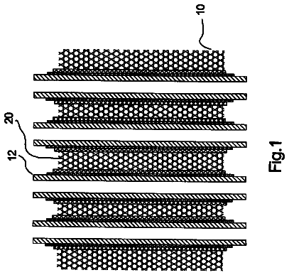
FIG. 1 is a cross-sectional view of a flat non-aqueous electrolyte secondary battery of the third embodiment;
FIG. 2 is an enlarged cross-sectional view of the section A of FIG. 1;
FIG. 3 is a partially cutaway perspective view schematically illustrating another flat non-aqueous electrolyte secondary battery of the third embodiment;
FIG. 4 is an enlarged cross-sectional view of the section B of FIG. 3;
FIG. 5 is an exploded perspective view of a battery pack of the fourth embodiment;
FIG. 6 is a block diagram illustrating the circuit of the battery pack shown in FIG. 5;
FIG. 7 shows a powder Cu-K.alpha.X-ray diffraction pattern of the composite material (negative electrode material) composed of the anatase titanium dioxide nanotubes and porous carbon obtained in Synthesis Example 1;
FIG. 8 shows a particle size distribution obtained from the X-ray small-angle scattering analysis of the composite material (negative electrode material) obtained in Synthesis Example 1;
FIG. 9 shows a particle size distribution obtained from the X-ray small-angle scattering analysis of the composite material (negative electrode material) obtained in Synthesis Example 2;
FIG. 10 shows initial charge and discharge curves of the electrochemical measurement cells of Example 1 and Comparative Example 1; and
FIG. 11 shows the retention rates of discharge cycle capacity of the electrochemical measurement cells of Example 1 and Comparative Example 1.
Detailed description
Hereinafter, the negative electrode material for a non-aqueous electrolyte secondary battery, method for manufacturing a negative electrode material for a non-aqueous electrolyte secondary battery, non-aqueous electrolyte secondary battery, and battery pack according to the embodiments are described below with reference to drawings. Throughout these embodiments, the same reference numbers are attached to the corresponding components, and overlapping explanation thereof is omitted. The respective drawings are schematic views for promoting the explanation and understanding of the embodiment. Therefore, the shape, dimension, and ratio of the components may be different from those in actual apparatus, but their design may be appropriately changed in consideration of the below-described explanation and known techniques.
(First Embodiment)
In general, according to first embodiment, a negative electrode material for a non-aqueous electrolyte secondary battery comprises a porous conductive particle and an active material formed on the surface and/or within the pores of the porous conductive particle and composed of a lithium titanium complex oxide having at least one structure selected from the group consisting of nanotubes and nanowires, the lithium titanium complex oxide being expressed by a general formula Li.sub.xTiO.sub.2 (where 0.ltoreq.x<1).
The active material exhibits a peak in the average particle size range of 1 nm or more and 10 nm or less as measured by X-ray small-angle scattering analysis using Cu-K.alpha. radiation and having a particle size which is distributed a range of 0.01 nm or more and 30 nm or less and distributed towards the high angle side with reference to the peak position in a particle size distribution. The data from the X-ray small-angle scattering analysis are analyzed using the origin scattering strength I
and radius of gyration Rg expressed by Guinier law shown in the formula (1).
.function..apprxeq..function..times..function..times..pi..times..times. ##EQU00001##
The formula
is obtained by taking logarithms of both sides of the formula (1).
.function..function..function..function..times..pi..times..times. ##EQU00002##
When the S.sup.2 and 1n [I(S)] in the formula
are plotted as abscissa and ordinate, respectively, a linear region appears. The radius of gyration Rg is determined from the gradient of the linear region and I
is determined from the intercept on the Y axis. The plot of ln [I(S)] corresponding to S.sup.2 is specifically called a Guinier plot. In the present application, the particle size distribution analysis was carried out using NANO-Solver manufactured by Rigaku Corporation as the analyzing software.
The porous conductive particle is made of, for example, a carbon or ceramic material. Examples of the ceramic material include oxide ceramic which has been conductive-coated with conductive titanium oxide, and non-oxide ceramic such as carbide, boride, and nitride. Considering conductive polymers are widely studied, a lighter material of conductive polymer having high electron conductivity would be suitable as the porous conductive particle may be found. However, there is a limit on the burning temperature of conductive polymers in the active material immersion process in the below-described production method.
The porous conductive particle is preferably made of carbon or conductive oxide, because these materials are suitable for the industrial production of mesoporous conductive particle.
Examples of the carbon include activated carbon and carbon black having a high specific surface area. Examples of the conductive oxide include conductive titanium oxide and zeolite-supported oxides having electron conductivity.
The carbon black is generally composed of non-spherical unique particle which is used in catalysts, and is preferably composed of hollow shell particle thinly covered with graphite crystal. The carbon black has a pore diameter of approximately several nanometers to several tens of nanometers, and has a large surface area and absorbs a large amount of oil. In addition, the carbon black has a high conductivity, and thus is particularly suitable to the porous conductive particle of the first embodiment.
The porous conductive particle preferably has an average particle size of 10 .mu.m or more and 50 .mu.m or less.
The porous conductive particle preferably has a porosity of 60 vol % or more and 95 vol % or less, and more preferably 80 vol % or more and 95 vol % or less. The nanotubes or nanowires preferably have an average diameter of 5 nm or more and 50 nm or less.
The content of the active material formed on the surface and/or within the pores of the porous conductive particle is preferably 60% by weight or more and 90% by weight or less, and more preferably 70% by weight or more and 80% by weight or less, based on the total weight of the porous conductive particle and the active material. If the content of the active material amount is more than 90% by weight, the active material layer formed on the surface of the porous conductive particle has a too large thickness. On the other hand, if the content of the active material amount is less than 60% by weight, it is difficult to increase the density of the negative electrode layer containing the active material.
The negative electrode material of the first embodiment preferably has a specific surface area of 200 m.sup.2/g or more and 400 m.sup.2/g or less as measured by the BET method.
The specific surface area is measured by allowing molecules having a known adsorption occupying area to adsorb to the surface of particle at a temperature of liquid nitrogen, and the specific surface area of the sample is determined from the amount of adsorption. The most common method is the BET method based on physical adsorption of an inactive gas at low temperature and low humidity. The BET method is the most famous theory for calculating the specific surface area, and is an extension of the Langmuir theory, which is a theory for monolayer molecular adsorption, to multilayer molecular adsorption. The specific surface area thus determined is referred tows the BET specific surface area.
The negative electrode material of the first embodiment preferably has a tap density of 0.3 g/cm.sup.3 or more, thereby improving the electrode density. In addition, in order to keep the form of nanotubes or nanofibers, the upper limit of the tap density is preferably 0.9 g/cm.sup.3 or more and 1.1 g/cm.sup.3 or less.
The tap density and bulk density may be measured by the method described in ASTM B-527-06. In this case, the measuring apparatus may be, for example, Dual Autotap (Quantacrome corp.) or Tap Pack Volumeter (Sahndon Southern Instruments Inc.). The powder to be measured is charged into a specific vessel by free fall, and the bulk density and tap density are calculated by the following formulae, where M, V, and N represent the mass (g), volume (cm.sup.3) and volume after tapping (cm.sup.3), respectively:
Bulk density=M/V (g/cm.sup.3)
Tap density-M/N (g/cm.sup.3)
According to the first embodiment described above, there is provided a negative electrode material for a non-aqueous electrolyte secondary battery which exhibits an electrode potential of 1.5 V or near 1.5 V with reference to lithium, which is equivalent to that of a titanic acid-based material, and has a higher energy density than the material.
More specifically, the negative electrode material for a non-aqueous electrolyte secondary battery comprises a porous conductive particle and an active material formed on the surface and/or within the pores of the porous conductive particle and composed of a lithium titanium complex oxide having at least one structure selected from the group consisting of nanotubes and nanowires, the lithium titanium complex oxide being expressed by a general formula Li.sub.xTiO.sub.2 (where 0.ltoreq.x<1). The nanotubes and the nanowires have three dimensional crystal structures, respectively. The active material is formed on the surface to be an electron conductivity surface and/or within the pores of the porous conductive particle. More specifically, the active material consisting of a lithium titanium complex oxide has a skeletal structure composed of titanium ion and oxide ion. The skeletal structure is arranged with the three dimensional stability and having spaces for hosting lithium ions between layers of the skeletal structure. The nanotubes or nanowires have larger contact areas with electrolytic solutions, because these have markedly smaller diameters than a particle of a bulk material with a diameter of several nanometers. Accordingly, the diffusion distance of lithium ions is reduced. In addition, the active material firmly combines to the surface and/or within pores of the porous conductive particle having electron conductivity. As a result, it can be compatible with both of the electron conductivity and lithium ion conductivity, which are important factors of an electrode. Accordingly, the negative electrode material allows more efficient insertion and extraction of lithium ions into and from the lithium ion hosting spaces in comparison with the bulk materials, and has a larger capacity owing to the virtually increased spaces for the insertion and extraction of lithium ions.
In the active material composed of a lithium titanium complex oxide having at least one structure selected from the group consisting of nanotubes and nanowires, it exhibits a peak in the average particle size range of 1 nm or more and 10 nm or less as measured by X-ray small-angle scattering analysis using Cu--K.alpha. radiation and having a particle size which is distributed a range of 0.01 nm or more and 30 nm or less and distributed towards the high angle side with reference to the peak position in a particle size distribution. Since such an active material has a uniform average particle size and aspect ratio to give good lithium ion conductivity, and a skeletal structure composed of titanium ions and oxide ions has a more stable three dimensional arrangement, the spaces to host lithium ions can be more stably formed between layers of the skeletal structure.
The nanotubes and nanowires having a diameter of 5 nm or more and 50 nm or less have larger contact areas with electrolytic solutions, whereby the diffusion distance of lithium ions is markedly reduced.
The negative electrode material for a non-aqueous electrolyte secondary battery of the first embodiment exhibits an electrode potential of near 1.5V with reference to lithium, which is equivalent to that of a titanic acid-based material, and has a higher energy density than the material.
The negative electrode material for a non-aqueous electrolyte secondary battery having a specific surface area of 200 m.sup.2/g or more to 400 m.sup.2/g or less as measured by the BET method has an increased contact area with electrolytic solutions. Therefore, for example, the host sites for insertion and extraction of lithium ions during charge and discharge are increased, whereby more lithium ions quickly move to the host sites. As a result, it can be obtained a non-aqueous electrolyte secondary battery in which the quick charge and discharge performance and electrode capacity is further improved.
(Second Embodiment)
In general, according to second embodiment, a method for manufacturing a negative electrode material for a non-aqueous electrolyte secondary battery comprises:
dispersing porous conductive particles in a titanium alkoxide solution to prepare a dispersion;
subjecting the dispersion to reduced pressure to infiltrate the titanium alkoxide solution on the surface and/or within pores of the porous conductive particles;
hydrolyzing the titanium alkoxide after the infiltration to form porous conductive particles containing titanium gel;
burning the porous conductive particles containing titanium gel in an inert gas atmosphere to convert the titanium gel on the surface and/or within the porous of the porous conductive particles to titanium oxide;
dispersing the porous conductive particles containing titanium oxide in an alkaline solution, followed by pressurizing and heating, thereby converting the titanium oxide on the surface and/or within the porous of the porous conductive particles to a titanium oxide having at least one structure selected from the group consisting of nanotubes and nanowires; and
carrying out the porous conductive particles containing titanium oxide to react with a lithium compound, thereby producing an active material formed on the surface and/or within the pores of the porous conductive particles and composed of a lithium titanium complex oxide having at least one structure selected from the group consisting of nanotubes and nanowires, the lithium titanium complex oxide being expressed by a general formula Li.sub.xTiO.sub.2 (where 0.ltoreq.x<1).
That is, firstly, titanium alkoxide is diluted with any solvent to make a titanium alkoxide solution. The titanium alkoxide may be, for example, titanium tetraisopropoxide. The solvent may be, for example, ethanol or 2-propanol.
Subsequently, porous conductive particles having an average particle size of, for example, 10 .mu.m or more and 50 .mu.m or less are dispersed in a titanium alkoxide solution to prepare dispersion.
The porous conductive particles may be prepared from the material described in the first embodiment.
When the surface of the porous conductive particles is hydrophilic, the solvent is preferably ethanol, while when the surface is hydrophobic, the solvent is preferably 2-propanol, thereby achieving good wettability of the particles for the solvent.
The preparation of the dispersion may include stirring or ultrasonic vibration, thereby uniformly dispersing the porous conductive particles in the titanium alkoxide solution.
Thereafter, the dispersion is subjected to reduced pressure to infiltrate the titanium alkoxide solution on the surface and/or within pores of the porous conductive particles. Subsequently, a mixed solution of pure water and ethanol (ethanol concentration: 20 to 50 wt %) is dropped on the dispersion to hydrolyze titanium alkoxide, thereby forming porous conductive particles containing titanium gel. After removing the excess portion of alkoxide by filtration, the titanium gel on the surface and/or within the porous of the porous conductive particles is converted to titanium oxide under heating in an inert gas atmosphere. The inert gas may be, for example, a noble gas such as nitrogen or argon gas. The heating temperature is preferably 400.degree. C. or higher and 600.degree. C. or lower. If the heating temperature is lower than 400.degree. C., the crystallinity deteriorates, and the negative electrode containing the negative electrode material thus obtained may have a low charge and discharge efficiency. On the other hand, if the heating temperature is higher than 600.degree. C., rutile titanium dioxide with a low charge and discharge capacity may be generated.
Subsequently, the porous conductive particles containing titanium oxide are dispersed in an alkaline solution to subject to hydrothermal treatment. The hydrothermal treatment may be carried out by any known method. The alkaline solution may be, for example, a sodium hydroxide aqueous solution or a lithium hydroxide aqueous solution. The porous conductive particles containing titanium oxide dispersed in an alkali are pressurized and heated using, for example, an autoclave pressure vessel, or subjected to hydrothermal synthesis treatment at high temperature and pressure. At this time, titanium oxide having at least one structure selected from the group consisting of nanotubes and nanowires is formed on the surface and/or within the porous of the porous conductive particles. In this manner, the use of TiO.sub.2, which has been combined with carbon, reduces the secondary aggregation of raw material particles and provides fine particles with uniform size in comparison with a method using TiO.sub.2 particles alone as raw material. As a result, nanotubes having a sharp particle size distribution are obtained.
Subsequently, the porous conductive particles containing titanium oxide having at least one structure selected from the group consisting of nanotubes and nanowires is washed with pure water. The water washing is carried out for removing the alkali metal ions of sodium or lithium contained in the alkaline solution. When lithium hydroxide is used, it is preferred that the water washing process be omitted thereby intentionally leaving lithium ions, and omitting the subsequent treatment process.
The porous conductive particles containing titanium oxide are dispersed in an organic solvent such as N-methylpyrrolidone. Thereafter, a binder such as polyvinylidene difluoride (PVdF) is added to prepare a paste, and the paste is applied to a metal foil to produce an electrode. Subsequently, lithium ions are electrochemically inserted, and thus producing an active material composed of a lithium titanium complex oxide expressed by a general formula Li.sub.xTiO.sub.2 (where 0.ltoreq.x<1).
Alternatively, the porous conductive particles containing titanium oxide having at least one structure selected from the group consisting of nanotubes and nanowires are dispersed in pure water, and being allowed to react with a lithium compound. As a result, a negative electrode material for a non-aqueous electrolyte secondary battery which comprises porous conductive particles and an active material formed on the surface and/or within the pores of each of the porous conductive particles and composed of a lithium titanium complex oxide having at least one structure selected from the group consisting of nanotubes and nanowires, is manufactured. The lithium titanium complex oxide is expressed by a general formula Li.sub.xTiO.sub.2 (where 0.ltoreq.x<1). The lithium compound is not particularly limited to lithium chloride, lithium hydroxide, or lithium carbonate, and is preferably lithium chloride or lithium hydroxide. These lithium compounds are preferred because they facilitate the adsorption to the surface of titanium dioxide in an aqueous solution.
The negative electrode material thus obtained is subsequently subjected to water washing and drying. Since the dried negative electrode material contains crystal water, it may be heated for dehydration at 400.degree. C. or more to 800.degree. C. or less.
The method according to the second embodiment manufactures a negative electrode material which has the above-described characteristics, and includes a porous conductive particle and an active material formed on the surface and/or within the pores of the porous conductive particle and composed of a lithium titanium complex oxide having at least one structure selected from the group consisting of nanotubes and nanowires, the lithium titanium complex oxide being expressed by a general formula Li.sub.xTiO.sub.2 (where 0.ltoreq.x<1).
According to the method of the second embodiment, the active material composed of a lithium titanium complex oxide having at least one structure selected from the group consisting of nanotubes and nanowires exhibits a peak in the average particle size range of 1 nm or more and 10 nm or less as measured by X-ray small-angle scattering analysis using Cu--K.alpha. radiation and having a particle size which is distributed a range of 0.01 nm or more and 30 nm or less and distributed towards the high angle side with reference to the peak position in a particle size distribution. In addition, a negative electrode material having a high specific surface area of, for example, 200 m.sup.2/g or more to 400 m.sup.2/g or less as measured by the BET method, and a tap density of 0.3 g/cm.sup.3 or more is manufactured.
(Third Embodiment)
In general, according to third embodiment, a non-aqueous electrolyte secondary battery comprises:
a positive electrode which inserts and extracts lithium;
a negative electrode containing a negative electrode material comprising a porous conductive particle and an active material formed on the surface and/or within the pores of the porous conductive particle and composed of a lithium titanium complex oxide having at least one structure selected from the group consisting of nanotubes and nanowires, the lithium titanium complex oxide being expressed by a general formula Li.sub.xTiO.sub.2 (where 0.ltoreq.x<1); and
a non-aqueous electrolyte.
The non-aqueous electrolyte secondary battery of the third embodiment includes an outer container. The positive electrode, negative electrode, and separator are contained in the outer container. The non-aqueous electrolyte is contained in the outer container.
The outer container, negative electrode, non-aqueous electrolyte, positive electrode, and separator are further described below.
1) Outer Container
The outer container is formed of a container made of a laminate film having a thickness of 0.5 mm or less, or a metal vessel having a thickness of 1.0 mm or less. The metal vessel more preferably has a thickness of 0.5 mm or less.
Examples of the shape of the outer container include flat (thin-type), square, cylinder, coin, and button. The outer container may be selected according to the size of the battery, and examples thereof include outer containers for small batteries mounted on portable electronic devices, and outer containers for large batteries mounted on two- to four-wheel vehicles.
The laminate film is a multilayer film composed of a metal layer sandwiched between resin films. The metal layer is preferably an aluminum foil or an aluminum alloy foil so as to reduce the weight of the battery. The resin film may be made of, for example, a polymer material such as polypropylene (PP), polyethylene (PE), nylon, or polyethylene terephthalate (PET). The laminate film may be formed into the shape of the outer container by heat sealing.
The metal vessel is made of, for example, aluminum or an aluminum alloy. The aluminum alloy preferably contains magnesium, zinc, silicon, or other element. The content of the transition metal such as iron, copper, nickel, or chromium in the aluminum or aluminum alloy is preferably 100 ppm by weight or less.
2) Negative Electrode
The negative electrode comprises a collector, and a negative electrode layer formed at least one surface of the collector and containing a negative electrode material and a binder.
The negative electrode material has the same structure as that described in the first embodiment, more specifically, includes porous conductive particles and an active material formed on the surface and/or within the pores of the porous conductive particles and composed of a lithium titanium complex oxide having at least one structure selected from the group consisting of nanotubes and nanowires, the lithium titanium complex oxide being expressed by a general formula Li.sub.xTiO.sub.2 (where 0.ltoreq.x<1). The active material in the negative electrode material preferably exhibits a peak in the average particle size range of 1 nm or more and 10 nm or less as measured by X-ray small-angle scattering analysis using Cu--K.alpha. radiation and having a particle size which is distributed a range of 0.01 nm or more and 30 nm or less and distributed towards the high angle side with reference to the peak position in a particle size distribution. The negative electrode material preferably has a specific surface area of 200 m.sup.2/g or more and 400 m.sup.2/g or less as measured by the BET method. The negative electrode material preferably has a tap density of 0.3 g/cm.sup.3 or more.
Examples of the binder include polytetrafluoroethylene (PTFE), polyvinylidene fluoride (PVdF), fluorine rubber, and styrene butadiene rubber.
The content of the binder in the negative electrode layer is preferably 2% by weight or more and 30% by weight or less. If the content of the binder is less than 2% by weight, bonding between the negative electrode layer and collector may deteriorate, so that the deterioration of cycling characteristics is taken place. On the other hand, in order to increase the capacity, the content of the binder is preferably 30% by weight or less.
A conductive agent may be added as necessary for improving the collecting performance and reducing the contact resistance of the negative electrode layer to the collector. The content of the conductive agent in the negative electrode layer is preferably 30% by weight or less.
The collector is made of a material which is electrochemically stable at potentials at which lithium is inserted and extracted in the active material of the negative electrode material. The collector is preferably made of copper, nickel, stainless steel, or aluminum. The average thickness of the collector is preferably from 5 to 20 .mu.m. When the thickness of the collector is within this range, the negative electrode has sufficient strength and lightness.
The negative electrode is produced by, for example, as follows: a negative electrode material and a binder are suspended in a common solvent to make slurry, and the slurry is applied to at least one surface of a collector, and dried to form a negative electrode layer, and then pressed.
Alternatively, in the production of the negative electrode, the negative electrode material and binder may be formed into a pellet, and used the pellet as a negative electrode layer.
3) Non-aqueous Electrolyte
The non-aqueous electrolyte may be a non-aqueous electrolyte gel composed of a liquid non-aqueous electrolyte, which has been prepared by dissolving an electrolyte in an organic solvent, a liquid electrolyte, and a polymer material.
The liquid non-aqueous electrolyte is prepared by dissolving an electrolyte in an organic solvent at a concentration of 0.5 mol/L or more and 2.5 mol/L or less.
Examples of the electrolyte include lithium salts such as lithium perchlorate (LiClO.sub.4), lithium hexafluorophosphate (LiPF.sub.6), lithium tetrafluoroborate (LiBF.sub.4), lithium hexafluoroarsenate (LiAsF.sub.6), lithium trifluorometasulfonate (LiCF.sub.3SO.sub.3), lithium bis(trifluoromethylsulfonylimide) [LiN(CF.sub.3SO.sub.2).sub.2], or mixtures thereof. The electrolyte is preferably resistant to oxidation even at high potentials, and most preferably LiPF.sub.6.
Examples of the organic solvent include cyclic carbonates such as propylene carbonate (PC), ethylene carbonate (EC), and vinylene carbonate, or linear carbonates such as diethyl carbonate (DEC), dimethyl carbonate (DMC), and methylethyl carbonate (MEC), or cyclic ethers such as tetrahydrofuran (THF), 2-methyltetrahydrofuran (2-MeTHF), and dioxolane (DOX), or linear ethers such as dimethoxyethane (DME) and diethoxyethane (DEE), or .gamma.-butyrolactone (GBL), acetonitrile (AN), sulfolane (SL), or mixtures thereof.
Examples of the polymer material include polyvinylidene fluoride (PVdF), polyacrylonitrile (PAN), and polyethylene oxide (PEO).
The non-aqueous electrolyte may be an ordinary temperature molten salt (ionic melt) containing lithium ions, a polymer solid electrolyte, or an inorganic solid electrolyte.
The term "ordinary temperature molten salt (ionic melt)" refers to an organic salt which is composed of an organic cation and an organic anion, and exists in liquid state at ordinary temperature (from 15 to 25.degree. C.) Examples of the ordinary temperature molten salt include those existing in a liquid state by themselves, those turning into a liquid state when mixed with an electrolyte, and those turning into a liquid state when dissolved in an organic solvent. The ordinary temperature molten salts commonly used in non-aqueous electrolyte secondary batteries have a melting point of 25.degree. C. or lower. The organic cation normally has a quaternary ammonium skeleton.
The polymer solid electrolyte is prepared by dissolving an electrolyte in a polymer material, followed by solidification.
The inorganic solid electrolyte is a solid substance having lithium ion conductivity.
4) Positive Electrode
The positive electrode comprises a collector, and a positive electrode layer formed on at least one surface of the collector and containing an active material and a binder.
Examples of the active material include oxides and sulfides. Specific examples of the active material include manganese dioxide inserting lithium (MnO.sub.2), iron oxide, copper oxide, nickel oxide, lithium manganese complex oxides (for example, Li.sub.xMn.sub.2O.sub.4 and Li.sub.xMnO.sub.2), lithium nickel complex oxides (for example Li.sub.xNiO.sub.2), lithium cobalt complex oxides (for example Li.sub.xCoO.sub.2), lithium nickel cobalt complex oxides (for example LiNi.sub.1-yCo.sub.yO.sub.2), lithium manganese cobalt complex oxides (for example Li.sub.xMn.sub.yCo.sub.1-yO.sub.2), spinel lithium manganese nickel complex oxides (Li.sub.xMn.sub.2-yNi.sub.yO.sub.4), olivine-type lithium phosphate oxides (for example, Li.sub.xFePO.sub.4, Li.sub.xFe.sub.1-yMn.sub.yPO.sub.4, and Li.sub.xCoPO.sub.4), iron sulfate [Fe.sub.2(SO.sub.4).sub.3], and vanadium oxides (for example, V.sub.2O.sub.5). The x and y preferably satisfy 0<x.ltoreq.1 and 0<y.ltoreq.1, respectively.
Examples of the active material giving a high positive electrode voltage include lithium manganese complex oxides (Li.sub.xMn.sub.2O.sub.4), lithium nickel complex oxides (Li.sub.xNiO.sub.2), lithium cobalt complex oxides (Li.sub.xCoO.sub.2), lithium nickel cobalt complex oxides (LiNi.sub.1-yCo.sub.yO.sub.2), spinel lithium manganese nickel complex oxides (Li.sub.xMn.sub.2-yNi.sub.yO.sub.4), lithium manganese cobalt complex oxides (Li.sub.xMn.sub.yCo.sub.1-yO.sub.2), lithium iron phosphates (Li.sub.xFePO.sub.4), and lithium nickel cobalt manganese complex oxides. The x and y preferably satisfy 0<x.ltoreq.1 and 0<y.ltoreq.1, respectively.
Among them, when the non-aqueous electrolyte contains an ordinary temperature molten salt, the use of lithium iron phosphate, Li.sub.xVPO.sub.4F, lithium manganese complex oxide, lithium nickel complex oxide, and lithium nickel cobalt complex oxide is preferred from the viewpoint of cycle life, thereby decreasing the reactivity between the positive electrode active material and ordinary temperature molten salt. The primary particle size of the positive electrode active material is preferably 100 nm or more and 1 .mu.m or less. The positive electrode active material having a primary particle size of 100 nm or more is easy to handle in the industrial production. The positive electrode active material having a primary particle size of 1 .mu.m or less allows smooth diffusion of lithium ions in the solid.
The specific surface area of the active material is preferably 0.1 m.sup.2/g or more and 10 m.sup.2/g or less. The active material having a specific surface area of 0.1 m.sup.2/g or more has sufficient sites for occluding and emitting lithium ions. The active material having a specific surface area of 10 m.sup.2/g or less is easy to handle in the industrial production, and offers good charge and discharge cycle performance.
Examples of the binder for binding the active material with the collector include polytetrafluoroethylene (PTFE), polyvinylidene fluoride (PVdF), and fluorine rubber.
A conductive agent may be added as necessary for improving the collecting performance and reducing the contact resistance of the positive electrode layer to the collector. Examples of the conductive agent include carbon materials such as acetylene black, carbon black, and graphite.
The proportion of the active material is preferably 80% by weight or more and 98% by weight or less, and the proportion of the binder is preferably 2% by weight or more and 20% by weight or less. When the proportion of the binder is 2% by weight or more, sufficient electrode strength is achieved, and when 20% by weight or less, the content of the insulator in the electrode is decreased, whereby the internal resistance is decreased.
When the amount of the conductive agent is 3% by weight or more, the addition effect of the conductive agent is achieved, and when 15% by weight or less, decomposition of the non-aqueous electrolyte on the surface of the conductive agent during storage at high temperatures is reduced.
The collector is preferably an aluminum foil or an aluminum alloy foil.
The average thickness of the aluminum foil or aluminum alloy foil is 5 .mu.m or more and 20 .mu.m or less, and more preferably 15 .mu.m or less. The purity of the aluminum foil is preferably 99% by weight or more. The aluminum alloy preferably contains magnesium, zinc, silicon, or other element. The content of the transition metal such as iron, copper, nickel, or chromium in the aluminum foil or aluminum alloy foil is preferably 1 wt % or less.
The positive electrode is produced by, for example, as follows: an active material, a binder, and a conductive agent that is added as necessary are suspended in an appropriate solvent to make slurry, the slurry is applied to at least one surface of a collector, and dried to form a positive electrode layer, followed by pressing.
Alternatively, in the production of the positive electrode, the active material, binder, and conductive agent, which is added as necessary, may be formed into a pellet, and used the pellet as a positive electrode layer.
5) Separator
Examples of the separator include porous films and synthetic resin nonwoven fabrics containing polyethylene, polypropylene, cellulose, or polyvinylidene fluoride (PVdF). Among them, porous film made of polyethylene or polypropylene is preferred thereby achieving a higher level of safety, because they are molten at a specific temperature to break the electric current.
The above-described electrode group including the negative electrode, positive electrode, and separator may have a winding structure or a laminated structure.
The non-aqueous electrolyte secondary battery of the third embodiment is described below in more detail with reference to FIGS. 1 and 2. FIG. 1 is a cross-sectional view of the thin-type non-aqueous electrolyte secondary battery of the third embodiment, and FIG. 2 is an enlarged cross-sectional view of the section A of FIG. 1.
A flattened wound electrode group 1 is contained in a bag-like outer container 2 which is made of a laminate film composed of two layers of resin film sandwiching a metal layer. The flattened wound electrode group 1 is formed by spirally winding and press-forming a laminate which is composed of, from the outside to the inside, a negative electrode 3, a separator 4, a positive electrode 5, and a separator 4. As shown in FIG. 2, the outermost negative electrode 3 is composed of a negative electrode collector 3a and a negative electrode layer 3b which is formed on one surface of the negative electrode collector 3a and contains the above-described a negative electrode material, the other portion of the negative electrode 3 is composed of the negative electrode collector 3a and negative electrode layers 3b formed on both surfaces of the negative electrode collector 3a. The positive electrode 5 is composed of a positive electrode collector 5a and positive electrode layers 3b formed on both surfaces of the positive electrode collector 5s.
The description continues in the full USPTO document.
 Lapsed, fee not paid8 drawings