 Lapsed, fee not paid5 drawings
Industrial Equipment · US 8,702,133 B2
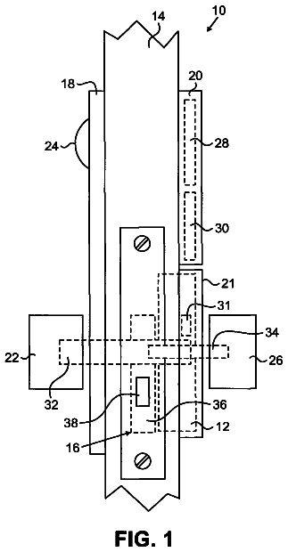
Bi-stable actuator for electronic lock
An actuator for an electronic door lock includes a stationary first magnet assembly, a beam, and a second magnet assembly.
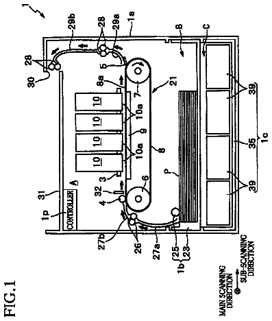
US 8,702,187 B2 · Assignee: Mimaki Engineering Co., Ltd. · Inventors: Ikeda; Akira et al.
Sheet 1 of 10 from the published document. All sheets in the USPTO PDF
A printer comprises: a vacuum table for supporting a jig which holds a medium; a printer head for discharging droplets; and a relative movement means for moving the printer head relative to the medium; a registration mark detection unit and barcode detection unit for acquiring holding platform information and support position information for the jig; and a controller for controlling the movement of the printer head by the relative movement means and controlling the discharge of droplets from the printer head on the basis of the holding platform information, the support position information and information pertaining to the desired pattern. As a result of this configuration, it is possible to generate image data without aligning the jig with a reference position on the vacuum table.
As examples of such a droplet discharge device, devices that manufacture color filters for color liquid crystal panels, and inkjet printers (hereinafter, "printer"), etc., are known in the art. An inkjet printer performs printing on a medium, which is supported by a platen, by discharging an ink while causing a printer head, which is arranged facing the platen, to move horizontally. For example, a printer is disclosed in Patent Document 1 that performs printing on a medium, which is placed on a platen, by discharging an ink from a printer head that is caused to move along a guide rail. As an example, printers are known that perform printing with ultraviolet curable ink (hereinafter, referred to as UV ink) that is cured when irradiated with an ultraviolet light. Because the UV ink has excellent weather resistance and water resistance properties, there is an advantage that a printed materi
1 of 10 drawing sheets so far from the published document, cropped to the drawing. Every sheet is in the USPTO PDF.
What the patent claimed, word for word. All of it is now free to use.
This application is a 371 of international application of PCT application serial no. PCT/JP2010/005278, filed on Aug. 26, 2010, which claims the priority benefit of PCT application no. PCT/JP2009/004122, filed on Aug. 26, 2009. The entirety of each of the above-mentioned patent applications is hereby incorporated by reference herein and made a part of this specification.
The present invention relates to a droplet discharge device and a droplet discharge method by which droplets are caused to adhere to a medium by discharging the droplets from a droplet discharge unit.
As examples of such a droplet discharge device, devices that manufacture color filters for color liquid crystal panels, and inkjet printers (hereinafter, "printer"), etc., are known in the art. An inkjet printer performs printing on a medium, which is supported by a platen, by discharging an ink while causing a printer head, which is arranged facing the platen, to move horizontally. For example, a printer is disclosed in Patent Document 1 that performs printing on a medium, which is placed on a platen, by discharging an ink from a printer head that is caused to move along a guide rail.
As an example, printers are known that perform printing with ultraviolet curable ink (hereinafter, referred to as UV ink) that is cured when irradiated with an ultraviolet light. Because the UV ink has excellent weather resistance and water resistance properties, there is an advantage that a printed material can be used for an outdoor advertisement flyer, etc., so that the printed material printed with the UV ink can be used for various purposes as compared with the printed matter printed with a water-soluble ink. The water-soluble ink penetrates the medium, and is cured inside the medium, whereas, the UV ink does not penetrate the medium, and is cured on the surface of the medium. Therefore, there is an advantage that printing can be performed on a medium made of a material, such as, vinyl chloride material, that does not easily allow penetration of the ink. Consequently, printing performed using the UV ink is widespread in the industrial field.
Recently, there is a demand for performing printing not only on sheet-like mediums but also on surfaces of various mediums having a three-dimensional shape. When performing printing on such three-dimensional mediums, merely placing the medium on the platen is not adequate to give it positional stability so that the printer cannot accurately recognize the position of the medium on the platen. Therefore, in the conventional technology, a jig that holds the medium is mounted is prepared and an operator accurately aligns a position of the jig relative to, for example, a reference position of a bed in a flatbed printer. Thus, when the medium is placed on the jig, the medium can be stably held and the position of the medium relative to the bed can be accurately recognized.
Patent Documents
Patent Document 1: Japanese Patent Application Laid-open No. 2005-45644
Problem to be Solved by the Invention
When mounting the jig on the bed as described above, it is necessary for the operator to mount the jig carefully by aligning the position thereof with the reference position of the bed. For example, the operator first mounts the jig on the bed and then gradually shifts the position of the jig until the position of the jig ultimately matches with the reference position. Therefore, this mounting operation requires time and leads to degradation of work efficiency. Because the operator has to perform the mounting operation manually, and match the position of the jig with the reference position with higher precision to improve the printing quality, there is an increased workload on the operator. Furthermore, when printing is to be performed in one sitting on mediums having different sizes, shapes, etc., each requiring a separate jig, it is difficult to match the type of the jig and the position on the bed to enable the printer to recognize the position of the medium.
The present invention is made in view of the above problems and it is an object of the present invention to provide a droplet discharge device and a droplet discharge method that provide improved work efficiency, put less workload on the operator, and can perform printing on mediums having various shapes.
Means for Solving the Problems
To achieve the above advantages, a droplet discharge device according to an aspect of the present invention includes a base member (for example, a vacuum table 13 according to the embodiments) that supports a holding platform (for example, a jig according to the embodiments) that holds a medium at a predetermined medium holding position; a droplet discharge unit (for example, a printer head 32 according to the embodiments) that discharges droplets; a relative movement unit (for example, a left-right moving mechanism and a front-back moving mechanism according to the embodiments) that moves the droplet discharge unit relative to the medium, while the medium is held against the holding platform that is supported by the base member; a holding-platform information acquiring unit (for example, registration mark detection units 34, 134, barcode detection units 35, 335, RFID reader, IC chip reader, magnetic head, CCD camera according to the embodiments) that acquires holding platform information (for example, information stored in or attached to barcodes 61, 61a, 352, 356, RFID tag, IC chip, magnetic stripe, thermosensitive sheet according to the embodiments) for identifying the holding platform and support position information relating to a support position of the holding platform mounted on the base member; and a discharge control unit (for example, a controller 22 according to the embodiments) that controls movement of the droplet discharge unit by the relative movement unit and discharge of the droplets from the droplet discharge unit, based on information relating to the holding platform identified in the holding platform information acquired from the holding-platform information acquiring unit, the support position information acquired by the holding-platform information acquiring unit, and information relating to an intended pattern, to cause the droplets to adhere to a surface of the medium held at the predetermined medium holding position to form the intended pattern.
A droplet discharge device according to another aspect of the present invention includes a base member that supports a holding platform that holds a medium at a predetermined medium holding position; a droplet discharge unit that discharges droplets; a relative movement unit that moves the droplet discharge unit relative to the medium, while the medium is held against the holding platform that is supported by the base member; a holding-platform information acquiring unit (for example, registration mark detection units 34, 134, barcode detection units 35, 335, RFID reader, IC chip reader, magnetic head, CCD camera according to the embodiments) that acquires holding platform information (for example, information stored in or attached to barcodes 61, 61a, 352, 356, RFID tag, IC chip, magnetic stripe, thermosensitive sheet according to the embodiments) for identifying the holding platform; and a discharge control unit that controls movement of the droplet discharge unit by the relative movement unit and discharge of the droplets from the droplet discharge unit, based on information relating to the holding platform identified in the holding platform information acquired from the holding-platform information acquiring unit and information relating to an intended pattern, to cause the droplets to adhere to a surface of the medium held at the predetermined medium holding position to form the intended pattern.
A droplet discharge device according to still another aspect of the present invention includes a base member that supports a holding platform that holds a medium at a predetermined medium holding position; a droplet discharge unit that discharges droplets; a relative movement unit that moves the droplet discharge unit relative to the medium, while the medium is held against the holding platform that is supported by the base member; a holding-platform information acquiring unit (for example, registration mark detection units 34, 134 according to the embodiments) that acquires support position information relating to a support position of the holding platform mounted on the base member; and a discharge control unit that controls movement of the droplet discharge unit by the relative movement unit and discharge of the droplets from the droplet discharge unit, based on the support position information acquired by the holding-platform information acquiring unit and information relating to an intended pattern, to cause the droplets to adhere to a surface of the medium held at the predetermined medium holding position to form the intended pattern.
It is preferable to provide an information reading unit that reads the holding platform information of the holding platform.
It is preferable to provide an alignment holding unit (for example, a positioning member according to the embodiments) that aligns and holds the holding platform at a predetermined support position on the base member, and that the support position information is acquired based on the position of the holding platform that has been positioned and held by the alignment holding unit.
It is preferable to provide reference marks (for example, a first registration mark 62a, a second registration mark 62b, a third registration mark 62c, and a third registration mark 62d according to the embodiments) on the holding platform that are used for acquiring the support position information, and that the holding-platform information acquiring unit detects the reference marks to acquire the support position information.
It is preferable that the holding platform information includes at least one piece of information among information that identifies a type of the holding platform, position information that indicates a holding position of the medium in the holding platform, layout information of the medium, quantity information, dimension information, and shape information.
It is preferable that the holding platform is box-shaped with a hollow portion inside, the hollow portion is connected to a suction unit (for example, a supply/drain blower 14 according to the embodiments) that can produce a negative pressure in the hollow portion, a suction hole that communicates with the hollow portion is formed in a portion of the holding platform that is just off the medium holding position, and an airflow that flows toward the hollow portion is produced in the suction hole by the suction unit.
A droplet discharge method is performed by a droplet discharge device that includes a base member that supports a holding platform that holds a medium at a predetermined medium holding position, a droplet discharge unit that discharges droplets, and a relative movement unit that moves the droplet discharge unit relative to the medium, while the medium is held against the holding platform that is supported by the base member. The droplet discharge method includes acquiring holding platform information that identifies the holding platform and support position information relating to a support position of the holding platform mounted on the base member; and controlling movement of the droplet discharge unit by the relative movement unit and discharge of the droplets from the droplet discharge unit, based on information relating to the holding platform identified in the holding platform information acquired at the acquiring, the support position information acquired at the acquiring, and information relating to an intended pattern, and causing the droplets to adhere to a surface of the medium held at the predetermined medium holding position to form the intended pattern.
A droplet discharge method is performed by a droplet discharge device that includes a base member that supports a holding platform that holds a medium at a predetermined medium holding position, a droplet discharge unit that discharges droplets, and a relative movement unit that moves the droplet discharge unit relative to the medium, while the medium is held against the holding platform that is supported by the base member. The droplet discharge method includes acquiring holding platform information that identifies the holding platform; and controlling movement of ink discharge unit by the relative movement unit and discharge of the droplets from the droplet discharge unit, based on information relating to the holding platform identified in the holding platform information acquired at the acquiring and information relating to an intended pattern, and causing the droplets to adhere to a surface of the medium held at the predetermined medium holding position to form the intended pattern.
A droplet discharge method is performed by a droplet discharge device that includes a base member that supports a holding platform that holds a medium at a predetermined medium holding position, a droplet discharge unit that discharges droplets, and a relative movement unit that moves the droplet discharge unit relative to the medium, while the medium is held against the holding platform that is supported by the base member. The droplet discharge method includes acquiring support position information relating to a support position of the holding platform mounted on the base member; and controlling movement of the droplet discharge unit by the relative movement unit and discharge of the droplets from the droplet discharge unit, based on the support position information acquired at the acquiring and information relating to an intended pattern, and causing the droplets to adhere to a surface of the medium held at the predetermined medium holding position to form the intended pattern.
Advantages of the Invention
A droplet discharge device according to an aspect of the present invention includes a holding-platform information acquiring unit that acquires holding platform information and support position information of a holding platform. Control of movement of a droplet discharge unit and discharge of droplets from the droplet discharge unit are performed based on information acquired by the holding-platform information acquiring unit, to cause the droplets to adhere to a surface of a medium to form an intended pattern. Therefore, printing can be performed on the medium held against the holding platform by creating image data based on the holding platform information that includes, for example, position information indicating holding position, layout information of the medium, quantity information, dimension information, and shape information, and the support position information of the holding platform. An operator needs to spend less time during this operation compared with the conventional device in which when mounting the holding platform, the operator is required to align the holding platform with a reference position of a base member. Consequently, work efficiency is improved.
The droplet discharge device according to another aspect of the present invention includes the holding-platform information acquiring unit that acquires the holding platform information. The control of the movement of the droplet discharge unit and the discharge of the droplets from the droplet discharge unit are performed based on the holding platform information acquired by the holding-platform information acquiring unit, to cause the droplets to adhere to a surface of a medium to form an intended pattern. Consequently, printing can be performed on the medium held against the holding platform by creating the image data to be printed based on the holding platform information, that indicates, for example, what type of the medium is held against the holding platform, how many, and the layout of the medium.
The droplet discharge device according to still another aspect of the present invention includes the holding-platform information acquiring unit that acquires the support position information of the holding platform. The control of the movement of the droplet discharge unit and the discharge of the droplets from the droplet discharge unit are performed based on the support position information acquired by the holding-platform information acquiring unit, to cause the droplets to adhere to a surface of a medium to form an intended pattern. Consequently, printing can be performed on the medium held against the holding platform by creating the image data to be printed based on the support position information that indicates a position where the holding platform is mounted on the base member.
It is preferable that an information reading unit that reads the holding platform information of the holding platform be provided. By this, the holding platform information can be acquired from the holding platform accurately and without mistake.
Furthermore, it is preferable that an alignment holding unit that aligns and holds the holding platform against the base member at a predetermined support position be provided. By this, the support position information can be easily acquired because the position of the holding platform on the base member is already known.
It is preferable that reference marks for acquiring the support position information be provided on the holding platform and the support position information be acquired by detecting the reference marks. By this, the image data is corrected based on the positions of the reference marks and printing on the medium held against the holding platform can be performed regardless of the position where the holding platform is mounted on the base member or an orientation in which the holding platform is mounted.
It is preferable that the holding platform information include at least one piece of information among information identifying a type of the holding platform, the position information indicating a holding position of the medium on the holding platform, the layout information of the medium, the quantity information, the dimension information, and the shape information. If the holding platform information includes the information identifying the type of the holding platform, the type of each of the holding platforms can be accurately identified when printing is performed by mounting a plurality of types of the holding platforms on the base member at the same time. If the holding platform information includes the position information indicating the holding position of the medium, the position of the medium on which printing is to be performed can be detected accurately. If the holding platform information includes the layout information of the medium, the image data to be printed can be easily created by laying out the image data based on the layout information. If the holding platform information includes the quantity information, the image data to be printed can be easily created by reproducing the image data based on the quantity information. If the holding platform information includes the dimension information, a printing target area can be accurately detected based on dimensions of the medium. If the holding platform information includes the shape information, the printing target area (a shape of the printing target area) can be accurately detected based on a shape of the medium.
It is preferable that the droplet discharge device be configured to produce, by a suction unit, airflow in a suction hole that flows toward a hollow portion. With this structure, the droplets that are discharged from the droplet discharge unit and suspended near the holding platform in the form of a mist are sucked into the hollow portion through the suction hole, and therefore are prevented from adhering to the medium or the droplet discharge unit.
A droplet discharge method according to an aspect of the present invention includes a step of acquiring the holding platform information at which the holding platform information and the support position information of the holding platform are acquired, and a step of discharge control at which control of the movement of the droplet discharge unit and control of the discharge of the droplets from the droplet discharge unit are performed based on the information acquired at the step of acquiring, to cause the droplets to adhere to the surface of the medium to form an intended pattern. Consequently, printing can be performed on the medium held against the holding platform based on the holding platform information, that indicates, for example, what type of the medium is held against the holding platform, how many, and the layout of the medium, and the support position information of the holding platform.
The droplet discharge method according to another aspect of the present invention includes a step of acquiring the holding platform information at which the holding platform information is acquired, and a step of discharge control at which control of the movement of the droplet discharge unit and control of the discharge of the droplets from the droplet discharge unit are performed based on the information acquired at the step of acquiring, to cause the droplets to adhere to the surface of the medium to form an intended pattern. Consequently, printing can be performed on the medium held against the holding platform by creating the image data to be printed based on the holding platform information, that indicates, for example, what type of the medium is held against the holding platform, how many, and the layout of the medium.
The droplet discharge method according to still another aspect of the present invention includes a step of acquiring the holding platform information at which the support position information of the holding platform is acquired, and a step of discharge control at which control of the movement of the droplet discharge unit and control of the discharge of the droplets from the droplet discharge unit are performed based on the information acquired at the step of acquiring, to cause the droplets to adhere to the surface of the medium to form an intended pattern. Consequently, printing can be performed on the medium held against the holding platform by creating the image data to be printed based on the support position information that indicates the position where the holding platform is mounted on the base member.
FIG. 1 is a perspective view of an outer appearance of a printer according to a first embodiment of the present invention.
FIG. 2 is a perspective view near a guide rail in the printer shown in FIG. 1.
FIG. 3 is a plan view of the printer shown in FIG. 1.
FIG. 4 is a cross-sectional view along a line IV-IV shown in FIG. 3.
FIG. 5 is a drawing showing a control system of the printer shown in FIG. 1.
FIG. 6 is a flowchart of operations performed when performing printing using the printer shown in FIG. 1.
FIG. 7 is a plan view of a printer according to a second embodiment of the present invention.
FIG. 8 is a plan view of a printer according to a third embodiment of the present invention.
FIG. 9 is a perspective view of a grid printer.
FIG. 10 is a plan view of a printer according to a fourth embodiment of the present invention.
Exemplary embodiments of the present invention are explained in detail below using first and second embodiments with reference to the accompanying drawings. For the sake of simplicity, an explanation will be given with the help of arrow directions that are shown in the drawings and defined as front-back, left-right, and up-down.
First Embodiment
A structure of a printer 1 according to the first embodiment of the present invention is explained with reference to FIGS. 1 to 5. A structure when printing is performed on a bottom surface of a truncated cone-shaped medium 8 by adhering UV ink thereto is explained below as an example. FIG. 1 is a perspective view of the printer 1. FIG. 2 is a perspective view of a printing unit 30 that is described later. FIG. 3 is a plan view of the printer 1. FIG. 4 is a cross-sectional view of a jig 50 that is described later and FIG. 5 is a drawing showing a control system of the printer 1.
As shown in FIG. 1, the printer 1 includes a supporting section 2 that is arranged at the bottom and a printing section 3 that is movable in a front-back direction above the supporting section 2. The supporting section 2 includes supporting legs 11, a main table body 12 that is horizontally supported by the supporting legs 11, a supply/drain blower 14, and a control unit 20. A rectangular vacuum table 13 is arranged in the central portion of the main table body 12. A not shown decompression chamber is arranged on the downside (backside) of the vacuum table 13. The surface of the vacuum table 13 communicates with the decompression chamber by a plurality of supply/drain holes 13a that runs through vertically (see FIG. 2).
The supply/drain blower 14 is connected to the decompression chamber and a drain tube 71, which is described later, and sucks in air and feeds air. By sucking the air from the decompression chamber through the supply/drain holes 13a, the supply/drain blower 14 causes a medium, etc., placed on the surface of the vacuum table 13 to be stuck to the vacuum table 13 by suction.
The control unit 20 is arranged on the front edge of the main table body 12. The control unit 20 includes an operating unit 21 that in turn includes operation switches, display devices, etc., and a built-in controller 22. The controller 22 performs operation control. That is, the controller 22 is electrically connected to the operating unit 21 and receives operation signals from the operating unit 21, and the controller 22 is electrically connected to various constituent parts, which are described later, and outputs the received operation signals to the various constituent parts.
Specifically, as shown in FIG. 5, the controller 22 controls driving of a left-right moving mechanism, a front-back moving mechanism, and the supply/drain blower 14, discharge of the UV ink from a printer head 32, and irradiation of ultraviolet light from a left ultraviolet radiation device 33L and a right ultraviolet radiation device 33R, all of which are described in detail later. A received light result output by a registration mark detection unit 34, which is described later, in response to an inspection light, and information read by a barcode detection unit 35 are supplied to the controller 22.
The printing section 3 includes a guide member 40 that extends in a left-right direction above the main table body 12, a built-in maintenance device 42 arranged on a right end of the guide member 40, and the printing unit 30 that is attached to guide rails 41 that extend in the left-right direction on the front surface of the guide member 40.
As shown in FIG. 1, an outer periphery of the printing unit 30 is covered by a cover 39. In FIG. 2, the printing unit 30 is shown with the cover 39 removed. As shown in FIG. 2, the printing unit 30 includes a single carriage 31, the printer head 32, the right ultraviolet radiation device 33R and the left ultraviolet radiation device 33L that are, respectively, arranged on the right and left sides of the printer head 32, the registration mark detection unit 34, and the barcode detection unit 35.
The single carriage 31 is coupled to the guide rails 41 so as to be movable in the left-right direction. The single carriage 31 serves as a mounting base for the printer head 32, the right ultraviolet radiation device 33R, the left ultraviolet radiation device 33L, the registration mark detection unit 34, and the barcode detection unit 35. One printer head 32 is arranged for ink of each color, for example, magenta, yellow, cyan, and black, and each printer head 32 includes a plurality of not shown discharge nozzles formed on a bottom surface thereof to discharge the UV ink downward. Each of the right ultraviolet radiation device 33R and the left ultraviolet radiation device 33L includes a not shown built-in UVLED capable of emitting the ultraviolet light downward.
The registration mark detection unit 34 includes on a bottom surface thereof a not shown light emitting unit and a not shown light receiving unit. The light receiving unit receives a reflected light of the inspection light that is emitted downward from the light emitting unit. When the registration mark detection unit 34 is moved over the jig 50 that is described later, the inspection light (a high-intensity inspection light) is reflected back from the portions where a first registration mark 62a to a fourth registration mark 62d are not formed, and the reflected light is received by the light receiving unit. On the other hand, no inspection light is emitted (or a low-intensity inspection light is emitted) by the light emitting unit over the portions where the first registration mark 62a to the fourth registration mark 62d are formed. Therefore, whether the first registration mark 62a to the fourth registration mark 62d are located below the registration mark detection unit 34 can be detected based on the received light result output by the light receiving unit.
A not shown reading unit is formed on the bottom surface of the barcode detection unit 35. When the barcode detection unit 35 is moved over a barcode 61 that is described later, the reading unit reads information encoded in the barcode 61. Four cap members 42a having a shape similar to that of the bottom surface of the printer heads 32 (the surfaces on which the discharge nozzles are formed) are arranged at prescribed positions on the upper surface of the maintenance device 42. With this structure, by moving the printing unit 30 to the right so that the printer heads 32 and the cap members 42a are vertically aligned and moving the cap members 42 upward, the bottom surface of the printer heads 32 can be covered with the cap members 42a. By doing so, the UV ink in the discharge nozzles can be prevented from drying (thickening) Reading of the barcode 61 by the barcode detection unit 35, for example, is similar to the operations performed by the registration mark detection unit 34.
The printing unit 30 is moved in the left-right direction along the guide rails 41 by a not shown left-right moving mechanism. The guide member 40 is slid, with the printing unit 30 and the maintenance device 42 mounted thereon as described above, in a front-back direction by a not shown front-back moving mechanism. Various known technologies can be used as the left-right moving mechanism and the front-back moving mechanism, and hence, the explanation thereof is omitted in the present specification.
When printing on, for example, a flat plate-like medium, the medium can be directly placed on the vacuum table 13. However, when performing printing on the bottom surface of the truncated cone-shaped medium 8, directly placing the medium on the vacuum table 13 makes its posture unstable, and the printer 1 cannot accurately recognize the position of the medium on the vacuum table 13. Therefore, by mounting the jig 50 according to the present embodiment on the vacuum table 13 and placing the medium 8 on the jig 50, the medium 8 can be stably held and the position accuracy can be ensured. A structure of the jig 50 is explained below with reference to FIGS. 3 and 4.
The jig 50 mounted on the vacuum table 13 is fixed to the vacuum table 13 by the action of the supply/drain blower 14. As shown in FIG. 4, the jig 50 is a box-like rectangular parallelepiped with a hollow portion 53 formed therein. Four containing recesses 55 that stably hold the medium 8 are formed on the upper portion of the jig 50, and a plurality of suction holes 52 communicating with the hollow portion 53 is formed around the containing recesses 55. A drain hole 54 communicating with the hollow portion 53 is formed on the left portion of the jig 50, and the drain tube 71 is connected thereto. A filter 72 that allows the air to pass and collects the ink that is suspended in the form of a mist is arranged on an edge of the drain tube 71 on the drain hole 54 side.
As shown in FIG. 3, the first registration mark 62a, the second registration mark 62b, the third registration mark 62c, and the fourth registration mark 62d are formed near four corners on the upper surface of the jig 50. The first registration mark 62a, the second registration mark 62b, the third registration mark 62c, and the fourth registration mark 62d are prepared as reference marks using a combination of a cross and a circle so as to surround the containing recesses 55, and at predetermined positions relative to the containing recesses 55. The barcode 61 is formed on, for example, the front edge on an upper surface of the jig 50 as an identifier that represents information relating to the jig 50.
The barcode 61 contains information, such as, outer dimensions of the jig 50, sizes and number of the containing recesses 55, number of the registration marks (the first registration mark 62a to the fourth registration mark 62d), a positional relation between two registration marks, positional relations of the containing recesses 55 relative to the registration marks, a registration mark (for example, the first registration mark 62a) that represents a reference mark among the plurality of the registration marks, and positional relations of the registration marks with respect to the reference mark to the barcode 61. As long as the information encoded in the barcode 61 can be read by the barcode detection unit 35, the barcode 61 can be formed on a side surface, etc., of the jig 50. Coordinates when a certain registration mark (for example, the first registration mark 62a) is set as the reference mark are set such that a direction defined by the first registration mark 62a and the second registration mark 62b is set as a first axis and a direction defined by the first registration mark 62a and the fourth registration mark 62d is set as a second axis.
The structure of the printer 1 is explained so far. Operations of the printer 1 when performing printing on the bottom surface of the truncated cone-shaped medium 8 by causing the UV ink to adhere thereto are explained with reference to a flowchart explained in FIG. 6.
At Step S101 of FIG. 6, the jig 50 is mounted on and fixed to the vacuum table 13. As described later, in the printer 1, the position of the medium 8 relative to the vacuum table 13 can be accurately detected irrespective of a mounting position and an orientation of the jig 50 relative to the vacuum table 13. Thus, the operator can mount the jig 50 on the vacuum table 13 without being particularly careful about the mounting position and the orientation of the jig 50. In FIG. 3, a case is explained as an example in which the jig 50 is mounted on the rectangular vacuum table 13 so as to be parallel in the left-right and front-back directions. However, the jig 50 need not necessarily be mounted in this manner. After the jig 50 is mounted on and fixed to the vacuum table 13, the medium 8 is placed inside each of the containing recesses 55 with the bottom surface of the medium 8 facing upward.
It is preferable that the jig 50 be mounted such that it is substantially parallel in the left-right and front-back directions to the rectangular vacuum table 13. When the jig 50 is mounted in this manner, as described later, the movement of the printing unit 30 performed by the left-right moving mechanism and the movement of the guide member 40 performed by the front-back moving mechanism can be reduced when detecting the first registration mark 62a to the fourth registration mark 62b. Consequently, the work efficiency can be improved by shortening the time required for printing.
At the next Step S102, the operator switches on, for example, a not shown "detect position" button on the operating unit 21 to output the operation signals from the controller 22 to the left-right driving mechanism and the front-back driving mechanism. Thereafter, the barcode detection unit 35 is moved in the left-right and/or front-back directions. As a result of this movement, when the barcode detection unit 35 comes above the barcode 61, the barcode detection unit 35 reads the information relating to the jig 50 that is encoded in the barcode 61, and outputs the information to the controller 22.
At Step S102, the operator can position the barcode detection unit 35 above the barcode 61 by manually operating the left-right driving mechanism and the front-back driving mechanism. It is preferable that a vertical position of the printing section 3 relative to the supporting section 2 be adjusted automatically according to a vertical height of the jig 50 obtained from the information detected by the barcode detection unit 35 as described above. With this structure, printing can be performed using the jig 50 having different vertical heights.
At the next Step S103, the controller 22 refers to the positional relation of the first registration mark 62a (reference mark) relative to the barcode 61 from the information obtained at Step S102. Thereafter, the controller 22 outputs the operation signals to the left-right driving mechanism and the front-back driving mechanism so as to position the registration mark detection unit 34 above and near the first registration mark 62a. When the registration mark detection unit 34 is placed above and near the first registration mark 62a, the controller 22 detects a received light status of the inspection light received by the receiving unit of the registration mark detection unit 34 while slightly moving the registration mark detection unit 34 in the left-right and/or front-back directions to detect the position of the first registration mark 62a relative to the vacuum table 13.
Once the position of the first registration mark 62a is detected, the controller 22 refers to the positional relation of the second registration mark 62b relative to the first registration mark 62a and positions the registration mark detection unit 34 above and near the second registration mark 62b. Subsequently, the controller 22 detects the position of the second registration mark 62b relative to the vacuum table 13 in a similar manner as for the first registration mark 62a. Similarly, the controller 22 detects the positions of the third registration mark 62c and the fourth registration mark 62d relative to the vacuum table 13 after the position of the second registration mark 62b is detected.
Thereafter, the controller 22 refers to the positions of the first registration mark 62a to the fourth registration mark 62d relative to the vacuum table 13 detected as described above, and the positional relation of each of the containing recesses 55 relative to the first registration mark 62a to the fourth registration mark 62d output from the barcode detection unit 35. In this case, the position of each containing recess 55 (the medium 8) relative to the vacuum table 13 can be calculated by matching each position of the first registration mark 62 output by the barcode detection unit 35 with each position of the first registration mark 62a to the fourth registration mark 62d relative to the vacuum table detected as described above. Thus, what kind of control is to be exerted over the discharge of the UV ink and the irradiation with the ultraviolet light when the printing unit 30 is moved to a specific position over the vacuum table 13 (a position in the left-right and front-back directions) to perform the desired printing on the bottom surface of the medium 8 is recognized by the controller 22.
The description continues in the full USPTO document.
About 6,512 words. The USPTO PDF has it with every drawing.
Fees are due 3.5, 7.5 and 11.5 years after grant. This patent expired on April 22, 2026, so the fee marked "not paid" was the one that went unpaid.
DROPLET DISCHARGE DEVICE AND DROPLET DISCHARGE METHOD
Filed Aug 2010 · published Jun 2012Droplet discharge device and droplet discharge method
Filed Aug 2010 · granted Apr 2014Earlier publications, parents and continuations. None of them can still be enforced, or this patent would not be listed.
Prior art cited by the examiner or applicant. Useful when you check your own idea for novelty.
Everything on this page comes from the documents linked above.