 Lapsed, fee not paid5 drawings
Hardware & Electronics · US 8,700,981 B2
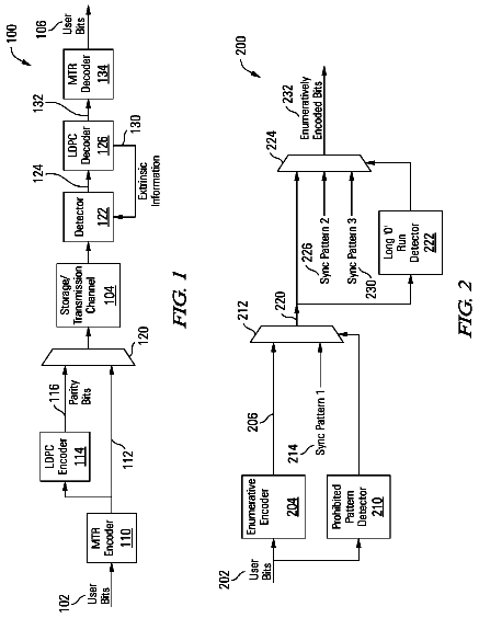
Low latency enumeration endec
Various embodiments of the present invention provide apparatuses and methods for encoding and decoding data.
US 8,701,131 B2 · Assignee: Sony Corporation · Inventors: Goto; Naofumi et al.
Sheet 1 of 75 from the published document. All sheets in the USPTO PDF
A disc conveying device includes a pair of rails positioned on opposite sides across a disc-shaped recording medium transported in the lead-in direction or ejecting direction in a direction orthogonal to a center axis direction, and extending in the direction of the conveyed disc-shaped recording medium; link arms that are turnably supported to a base chassis, are turnable as to the pair of rails, and move in parallel in a direction of separating the rails from the peripheral face of the disc-shaped recording medium; conveying rollers that convey the disc-shaped recording medium by being supported by the rails, and touch the peripheral face of the disc-shaped recording medium with at least one conveying roller rotating; and an ejecting lever that is turnable as to at least one of the rails, by which turning the peripheral face of the disc-shaped recording medium is pressed, and the disc-shaped recording medium is conveyed.
The present disclosure relates to the technical field of a disc conveying device, and particularly relates to the technical field wherein a disc-shaped recording medium, which is conveyed by a conveying roller supported by rails, is ejected by an ejecting lever, which is supported by rails, being pressed, whereby the ejected amount of disc-shaped recording medium is increased while ensuring simplicity of the mechanism thereof. There are disc conveying devices that convey disc-shaped recording medium on which image data and audio data are recorded. For example, there is such a disc conveying device wherein a pair of driving belts is disposed on opposite sides, sandwiching the disc-shaped recording medium, and the disc-shaped recording medium is conveyed by having the driving belts pressed against the peripheral face of the disc-shaped recording medium so as to feed the disc (e.g., Japanes
1 of 75 drawing sheets so far from the published document, cropped to the drawing. Every sheet is in the USPTO PDF.
What the patent claimed, word for word. All of it is now free to use.
The present disclosure relates to the technical field of a disc conveying device, and particularly relates to the technical field wherein a disc-shaped recording medium, which is conveyed by a conveying roller supported by rails, is ejected by an ejecting lever, which is supported by rails, being pressed, whereby the ejected amount of disc-shaped recording medium is increased while ensuring simplicity of the mechanism thereof.
There are disc conveying devices that convey disc-shaped recording medium on which image data and audio data are recorded. For example, there is such a disc conveying device wherein a pair of driving belts is disposed on opposite sides, sandwiching the disc-shaped recording medium, and the disc-shaped recording medium is conveyed by having the driving belts pressed against the peripheral face of the disc-shaped recording medium so as to feed the disc (e.g., Japanese Unexamined Patent Application Publication No. 11-328799).
Also, there is a disc conveying device wherein multiple feeding rollers are disposed on opposite sides, sandwiching the disc-shaped recording medium, and the feeding rollers press against, and cause to rotate, the peripheral face of the disc-shaped recording medium, thereby conveying the disc-shaped recording medium (e.g., Japanese Patent No. 3640174 and Japanese Patent No. 3690300).
Now, with a disc conveying device that handles a disc-shaped recording medium as described above, a large conveying distance disc-shaped recording medium has to be secured to securely convey the disc-shaped recording medium to the conveying position, ensuring conveying distance. For example, in the case of ejecting the disc-shaped recording medium and storing in a disc cartridge, the disc-shaped recording medium has to be conveyed until the entire disc-shaped recording medium is inserted into the disc cartridge.
However, in a disc conveying device disclosed in Japanese Unexamined Patent Application Publication No. 11-328799, the disc-shaped recording medium is held between a pair of belts from both sides, between a state wherein the center of the disc-shaped recording medium is positioned between one edge of the belts and a state wherein the center of the disc-shaped recording medium is positioned between the other edge of the belts.
Accordingly, since the conveying distance of the disc-shaped recording medium is the same distance as the length of the pair of belts, sufficient conveying distance for the disc-shaped recording medium is not secured.
Also, in disc conveying devices disclosed in Japanese Patent No. 3640174 and Japanese Patent No. 3690300, the conveying distance of the disc-shaped recording medium is a distance wherein contact with the feeding roller is secured, whereby sufficient conveying distance for the disc-shaped recording medium is not secured.
In this case, conveying the disc-shaped recording medium with a separate feeding mechanism following the conveying by the conveying mechanism which has a driving belt and feeding rollers may be considered, but if a separate feeding mechanism from the conveying mechanism such as driving belt and feeding rollers is used, the mechanism provided to the disc conveying device becomes that much more complex.
It has been found desirable to provide a disc conveying device which increases the ejected amount of the disc-shaped recording medium while ensuring simplicity of the mechanism thereof.
A disc conveying device according to an embodiment of the present disclosure includes: a pair of rails positioned on opposite sides across a disc-shaped recording medium transported in the lead-in direction or ejecting direction in a direction orthogonal to a center axis direction, and extending in the direction of the conveyed disc-shaped recording medium; a plurality of link arms that are turnably supported to a base chassis, are turnable as to the pair of rails, and move in parallel in a direction of separating the pair or rails from the peripheral face of the disc-shaped recording medium; conveying rollers that convey the disc-shaped recording medium by being supported by the rails, and touch the peripheral face of the disc-shaped recording medium with at least one conveying roller rotating; and an ejecting lever that is turnable as to at least one of the rails, by which turning the peripheral face of the disc-shaped recording medium is pressed, and the disc-shaped recording medium is conveyed.
According to this configuration, with the disc conveying device, the disc-shaped recording medium is conveyed by conveying rollers supported by rails, and the disc-shaped recording medium is ejected by an ejecting lever which turns as to the rail.
The ejecting lever preferably further includes a pressing roller that presses the peripheral face of the disc-shaped recording medium. By providing the ejecting lever with the pressing roller that presses the peripheral face of the disc-shaped recording medium, the pressing roller comes into sliding contact with the peripheral face of the disc-shaped recording medium, thereby conveying the disc-shaped recording medium.
The disc conveying device preferably further includes a storage to retract and store the ejecting lever from the conveying path of the disc-shaped recording medium, when the ejecting lever is not pressing the disc-shaped recording medium. By providing a storage to retract and store the ejecting lever from the conveying path when the ejecting lever is not pressing the disc-shaped recording medium, the disc-shaped recording medium does not touch the ejecting lever.
The pressing roller preferably functions as the conveying roller to convey the disc-shaped recording medium when the ejecting lever is in a state of being stored in the storage. By the pressing roller functioning as the conveying roller to convey the disc-shaped recording medium when the ejecting lever is in a state of being stored in the storage, two functions, of a function to eject the disc-shaped recording medium with a pressing roller and a function to convey the disc-shaped recording medium, are executed.
The storage is preferably attached to the rail. By attaching the storage to the rail, dedicated space for disposing the storage does not have to be provided.
The storage preferably further includes a lever guiding face that guides the stored ejecting lever and a disc guiding face that guides the conveyed disc-shaped recording medium. By providing a lever guiding face that guides the stored ejecting lever and a disc guiding face that guides the conveyed disc-shaped recording medium, the ejecting lever is guided by the lever guiding face and stored in the storage, and the disc-shaped recording medium is guided by the disc guiding face when being conveyed.
The disc conveying device preferably further includes a biasing spring that biases the ejecting lever in the direction to be stored in the storage. By providing a biasing spring that biases the ejecting lever in the direction to be stored in the storage, when the ejecting lever is stored in the storage, turning force is applied in the direction of the ejecting lever to be stored in the storage.
The ejecting lever is preferably turnably supported by the link arm. By the ejecting lever being turnably supported by the link arm, the link arm and ejecting lever are turnable as to the rails.
The disc conveying device preferably further includes a cam engaging portion on the ejecting lever, and an operating cam portion wherein a cam engaging portion of the ejecting lever is slidably engaged with the base chassis and the ejecting lever is turned on a predetermined path. By providing a cam engaging portion on the ejecting lever, and providing an operating cam portion wherein a cam engaging portion of the ejecting lever is slidably engaged with the base chassis and the ejecting lever is turned on a predetermined path, the cam engaging portion is slid against the operating cam portion when the ejecting lever is turned.
The disc conveying device preferably further includes a spring member that biases the pair of rails so that the conveying roller approaches the peripheral face of the disc-shaped recording medium. By providing a spring member that biases the pair of rails so that the conveying roller approaches the peripheral face of the disc-shaped recording medium, the conveying roller is pressed to the peripheral face of the disc-shaped recording medium by the biasing force of the spring member at the time of conveying the disc-shaped recording medium.
The pair of rails synchronously are preferably moved in parallel in the direction of mutually separating. By causing the pair of rails synchronously to be moved in parallel in the direction of mutually separating, the disc-shaped recording medium can be conveyed along a path that is in a straight line.
The disc conveying device preferably further includes stoppers, each touching a respective rail of the pair of rails moved in the direction of separating from the peripheral face of the disc-shaped recording medium, thereby restricting the movement of the pair of rails. By providing stoppers, each touching a respective rail of the pair of rails moved in the direction of separating from the peripheral face of the disc-shaped recording medium, thereby restricting the movement of the pair of rails, the movement of the pair of rails in the direction of mutually separating is restricted by the stoppers.
The disc conveying device preferably further includes side sliders that move in the same direction as the conveying direction of the disc-shaped recording medium, according to the conveying position of the disc-shaped recording medium; the side sliders further including the stoppers. By providing side sliders that move in the same direction as the conveying direction of the disc-shaped recording medium, according to the conveying position of the disc-shaped recording medium, the side sliders further including the stoppers, the movement of the pair of rails in the direction of mutually separating is restricted by the side sliders.
The disc conveying device preferably further includes multiple stopper engaging pieces on the rails that touch the stoppers according to the movement position of the side sliders. By proving multiple stopper engaging pieces on the rails that touch the stoppers according to the movement position of the side sliders, the movement of the pair of rails is restricted in different positions, according to the position of the side sliders.
The contact positions of the stopper engaging pieces and the stopper are preferably in different positions in the moving direction of the rails. By positioning the stopper engaging pieces and the stopper in different positions in the moving direction of the rails, the stopper makes contact with the stopper engaging piece according to the position of the side slider, and the movement of the pair of rails is restricted in different positions.
A disc conveying device according to an embodiment of the present disclosure includes: a pair of rails positioned on opposite sides across a disc-shaped recording medium transported in the lead-in direction or ejecting direction in a direction orthogonal to a center axis direction, and extending in the direction of the conveyed disc-shaped recording medium; a plurality of link arms that are turnably supported to a base chassis, are turnable as to the pair of rails, and move in parallel in a direction of separating the pair or rails from the peripheral face of the disc-shaped recording medium; conveying rollers that convey the disc-shaped recording medium by being supported by the rails, and touch the peripheral face of the disc-shaped recording medium with at least one conveying roller rotating; and an ejecting lever that is turnable as to at least one of the rails, by which turning the peripheral face of the disc-shaped recording medium is pressed, and the disc-shaped recording medium is conveyed.
Accordingly, by ejecting the disc-shaped recording medium with the ejecting lever that is turnable as to the rails, a dedicated mechanism to convey the disc-shaped recording medium does not have to be provided, and the ejected amount of disc-shaped recording mediums can be increased while insuring simplicity of the mechanism.
The ejecting lever may include a pressing roller that presses the peripheral face of the disc-shaped recording medium. Accordingly, the pressing roller comes into sliding contact with the peripheral face of the disc-shaped recording medium, thereby securing smooth conveying operations of the disc-shaped recording medium.
A storage may be provided to retract and store the ejecting lever from the conveying path of the disc-shaped recording medium, when the ejecting lever is not pressing the disc-shaped recording medium. Accordingly, the ejecting lever does not obstruct the conveying operations of the disc-shaped recording medium, whereby smooth conveying operations of the disc-shaped recording medium can be performed.
The pressing roller may function as the conveying roller to convey the disc-shaped recording medium when the ejecting lever is in a state of being stored in the storage. Accordingly, two functions are executed, which are a function to eject the disc-shaped recording medium with a pressing roller and a function to convey the disc-shaped recording medium, whereby the functionality of the ejecting lever is improved and the number of parts is reduced.
The storage may be attached to the rail. Accordingly, dedicated space for disposing the storage does not have to be provided, and the disc conveying device can be reduced in size due to the space reduction, and contact of the disc-shaped recording medium and the storage during conveying of the disc-shaped recording medium can be suppressed.
The storage may include a lever guiding face that guides the stored ejecting lever and a disc guiding face that guides the conveyed disc-shaped recording medium. Accordingly, the ejecting lever and the disc-shaped recording medium are securely guided and the ejecting lever is securely stored in the storage, while smoothly conveying the disc-shaped recording medium.
The disc conveying device may include a biasing spring that biases the ejecting lever in the direction to be stored in the storage. Accordingly, when the ejecting lever is stored in the storage, turning force is applied to the ejecting lever in the direction of storing in the storage, whereby the ejecting lever can be securely stored in the storage, while suppressing the ejecting lever from unnecessarily exiting the storage when a vibration or the like occurs.
The ejecting lever may be turnably supported by the link arm. Accordingly, the link arm and ejecting lever are turnable as to the rails, whereby the freedom of the turning path of the ejecting lever can be improved in that amount, whereby the ejecting amount of disc-shaped recording mediums from the disc conveying device can be increased.
The disc conveying device may include a cam engaging portion on the ejecting lever, and an operating cam portion wherein a cam engaging portion of the ejecting lever is slidably engaged with the base chassis and the ejecting lever is turned on a predetermined path. Accordingly, the freedom of the turning path of the ejecting lever can be improved.
The disc conveying device may include a spring member that biases the pair of rails so that the conveying roller approaches the peripheral face of the disc-shaped recording medium. Accordingly, the conveying roller is pressed to the peripheral face of the disc-shaped recording medium by the biasing force of the spring member at the time of conveying the disc-shaped recording medium, whereby friction between the peripheral face of the disc-shaped recording medium and the conveying roller increases, and the disc-shaped recording medium can be securely conveyed.
The pair of rails may be synchronously moved in parallel in the direction of mutually separating. Accordingly, the disc-shaped recording medium can be conveyed along a path that is in a straight line, whereby conveying operations of the disc-shaped recording medium can be readily performed, while shortening the conveying distance of the disc-shaped recording medium and miniaturizing the disc conveying device.
The disc conveying device may include stoppers, each touching a respective rail of the pair of rails moved in the direction of separating from the peripheral face of the disc-shaped recording medium, thereby restricting the movement of the pair of rails. Accordingly, the movement of the pair of rails in the direction of mutually separating is restricted by the stoppers, whereby excessive movement of the turning arm is restricted, and smooth operations of the pair of rails can be secured.
The disc conveying device may include side sliders that move in the same direction as the conveying direction of the disc-shaped recording medium, according to the conveying position of the disc-shaped recording medium; the side sliders further including the stoppers. Accordingly, dedicated members to provide the stoppers do not have to be made, and the number of parts can therefore be reduced.
The disc conveying device may include multiple stopper engaging pieces on the rails that touch the stoppers according to the movement position of the side sliders. Accordingly, the movement of the pair of rails is restricted, each in appropriate positions, according to the position of the side sliders, and operations from each position of the pair of rails can be smoothly started.
The contact positions of the stopper engaging pieces and the stopper may be in different positions in the moving direction of the rails. Accordingly, movement of the pair of rails at the various positions can be readily restricted.
FIG. 1 is a perspective view of a disc cartridge in which a disc-shaped storage medium that is conveyed by the disc conveying device is stored, and illustrates an embodiment of a disc conveying device according to the present disclosure, together with FIGS. 2 through 75;
FIG. 2 is a perspective view of the disc cartridge illustrating a state of having a first shell and second shell separated;
FIG. 3 is a perspective view of the disc cartridge illustrating a state of having a first shell and second shell separated, as seen from a different direction than in FIG. 2;
FIG. 4 is a cross-sectional diagram of the disc cartridge illustrating a state in which the first and second shells are locked with a lock slider;
FIG. 5 is a perspective view of the disc conveying device;
FIG. 6 is an exploded perspective view of the disc conveying device;
FIG. 7 is a schematic plan view illustrating the members primarily disposed on the upper side of a base chassis;
FIG. 8 is a schematic plan view illustrating the members primarily disposed on the lower side of the base chassis;
FIG. 9 is a perspective view illustrating a base frame and base plate;
FIG. 10 is a perspective view illustrating a base frame, unit plate, and base plate;
FIG. 11 is an enlarged exploded perspective view illustrating a route adjuster on the left side and a first front side link arm and so forth;
FIG. 12 is an enlarged exploded perspective view illustrating a route adjuster on the right side and a second front side link arm and so forth;
FIG. 13 is an enlarged exploded perspective view illustrating a state viewing a route adjuster on the right side and a second front side link arm and so forth from a different direction from FIG. 12;
FIG. 14 is an enlarged side face view of a route adjuster;
FIG. 15 is a schematic plan view illustrating a state wherein a route adjuster is in a central position, and illustrate the actions of the route adjuster together with FIGS. 16 and 17;
FIG. 16 is a schematic expanded plan view illustrating a state wherein the route adjuster is turned in one direction;
FIG. 17 is a schematic expanded plan view illustrating a state wherein the route adjuster is turned in another direction;
FIG. 18 is a perspective view of a base chassis;
FIG. 19 is a perspective view of a floor side of a first base of the base chassis and a spring member;
FIG. 20 is an enlarged exploded perspective view illustrating a driving motor and the gears and so forth;
FIG. 21 is an enlarged exploded perspective view illustrating a pulley holder and a chucking pulley;
FIG. 22 is an enlarged perspective view illustrating a chucking pulley being held by a pulley holder;
FIG. 23 is a plan view illustrating a state wherein a first pulley holder and second pulley holder are closed;
FIG. 24 is a plan view illustrating a state wherein a first pulley holder and second pulley holder are open;
FIG. 25 is an exploded perspective view illustrating an interlocking lever and a starting level;
FIG. 26 is an exploded perspective view illustrating a first main slider and sub slider;
FIG. 27 is a perspective view illustrating the first main slider and sub slider;
FIG. 28 is an enlarged perspective view illustrating a portion of the sub slider and an operating lever and so forth;
FIG. 29 is a perspective view illustrating a second main slider;
FIG. 30 is a perspective view illustrating a side slider;
FIG. 31 is a perspective view illustrating a first main slider and sub slider and a second main slider and side slider;
FIG. 32 is a perspective view illustrating a first link mechanism and storage;
FIG. 33 is a perspective view separately illustrating the first link mechanism and storage;
FIG. 34 is an enlarged perspective view illustrating a first front side link arm and ejecting level;
FIG. 35 is a schematic enlarged plan view illustrating a state of a pressing roller and so forth being stored in a storage;
FIG. 36 is a perspective view illustrating a second link mechanism;
FIG. 37 is a schematic plan view illustrating an initial state of the link mechanism and so forth, and illustrates the operations of the disc conveying device together with FIGS. 38 through 75;
FIG. 38 is a schematic plan view illustrating an initial state of the slider and so forth;
FIG. 39 is a schematic side view illustrating an initial state of the unit plate and so forth;
FIG. 40 is a schematic plan view illustrating a state wherein a loading operation is started, and the disc-shaped recording medium is conveyed towards a chucking position;
FIG. 41 is a schematic plan view illustrating a state wherein the disc-shaped recording medium continues to be conveyed towards a chucking position;
FIG. 42 is a schematic enlarged plan view illustrating a state wherein an operating lever is pressed and turned by a slave shaft of a limit lever;
FIG. 43 is a schematic plan view illustrating a state wherein the disc-shaped recording medium continues to be conveyed towards a chucking position;
FIG. 44 is a schematic plan view illustrating a state wherein a stopper engaging piece of the first rail touches a stopper of the side slider during conveying of the disc-shaped recording medium;
FIG. 45 is a schematic enlarged plan view illustrating a state wherein the ejecting lever is turned and the pressing roller and so forth are stored in the storage;
FIG. 46 is a schematic plan view illustrating a state wherein the disc-shaped recording medium continues to be conveyed towards a chucking position;
FIG. 47 is a schematic plan view illustrating a state wherein the disc-shaped recording medium continues to be conveyed towards a chucking position;
FIG. 48 is a schematic plan view illustrating a state wherein the disc-shaped recording medium continues to be conveyed towards a chucking position;
FIG. 49 is a schematic plan view illustrating a state wherein the sub slider is moved to the rear;
FIG. 50 is a schematic plan view illustrating a state wherein the first main slider and sub slider are integrated and moved to the rear;
FIG. 51 is a schematic side view illustrating a state of the unit plate being moved upwards;
FIG. 52 is a schematic plan view illustrating a state wherein the first main slider and sub slider have been moved to the moving edge at the rear;
FIG. 53 is a schematic plan view illustrating a state wherein the first rail and second rail are moved in directions so as to mutually separate from each other, and a pressing roller and rotating roller and disc holding pin are separated from the peripheral face of the disc-shaped recording medium;
FIG. 54 is a schematic plan view illustrating a state wherein a stopper engaging piece of the first rail is touching the stopper of the side slider during chucking of the disc-shaped recording medium;
FIG. 55 is schematic side view illustrating a state wherein the unit plate has been moved to the upper moving edge;
FIG. 56 is a schematic plan view illustrating a state wherein an ejecting operation has started, and the disc-shaped storage medium is conveyed toward the disc cartridge;
FIG. 57 is an enlarged perspective view illustrating a state wherein the route adjuster is turned, and the positioning protrusion is inserted into a holding groove in the disc cartridge and the position thereof determined;
FIG. 58 is an enlarged side view illustrating a state wherein the route adjuster is turned, and the positioning protrusion is inserted into a holding groove in the disc cartridge and the position thereof determined;
FIG. 59 is a schematic enlarged plan view illustrating a state wherein an operating lever is pressed by the slave shaft of the limit lever, and movement of the sub slider towards the front has begun;
FIG. 60 is a schematic enlarged plan view illustrating a state wherein the slave shaft of the limit layer is moved so as to pass the operating lever;
FIG. 61 is a schematic enlarged plan view illustrating a state wherein the slave shaft of the limit lever is pressed by the first main slider and movement of the first rail towards the front has begun;
FIG. 62 is a schematic plan view illustrating a state of the first main slider and sub slider are integrated and moved toward the front from a non-meshed position;
FIG. 63 is a schematic enlarged plan view illustrating a state wherein the first main slider and sub slider are integrated and moved toward the front from a non-meshed position, and the sub slider is locked as to the first main slider by a locking lever;
FIG. 64 is a schematic side view illustrating a state of the unit plate when the side slider is moved towards the front;
FIG. 65 is a schematic plan view illustrating a state wherein the disc-shaped recording medium has pressed by a pressing roller and is conveyed towards the disc cartridge;
FIG. 66 is a perspective view illustrating a state wherein an ejecting lever is slid by a sliding protrusion and the pressing roller is moved downwards;
FIG. 67 is a schematic side view illustrating a state wherein the disc-shaped recording medium is pressed by the pressing roller and stored in the disc cartridge;
FIG. 68 is a schematic plan view illustrating a state wherein the disc-shaped recording medium continues to be pressed by the pressing roller and is conveyed toward the disc cartridge;
FIG. 69 is a schematic plan view illustrating a state wherein the disc-shaped recording medium continues to be pressed by the pressing roller and is stored in the disc cartridge;
FIG. 70 is a schematic side view illustrating a state wherein the disc-shaped recording medium is pressed by the pressing roller and stored in the disc cartridge;
FIG. 71 is a schematic plan view illustrating an tension spring supported between the limit lever and first rail is extended in the event that the disc-shaped recording medium is pressed forward excessively by the pressing roller;
FIG. 72 is a schematic enlarged plan view illustrating a state immediately following the first main slider and sub slider having been moved from the forward moving edge to a non-meshed position, and illustrates the operations of the locking lever and so forth when the first main slider and sub slider are moved from the forward moving edge toward the non-meshed position in the rear, together with FIGS. 73 and 75;
FIG. 73 is a schematic enlarged plan view illustrating a state wherein the first main slider and sub slider continue to be moved toward the rear, and the sub slider lock is disengaged by the locking lever when the meshing of the second main rack portion and driving gear of the first main slider is disengaged;
FIG. 74 is a schematic enlarged plan view illustrating a state wherein the first main slider and sub slider continue to be moved toward the rear, and the meshing of the second sub rack portion and driving gear of the sub slider is disengaged; and
FIG. 75 is a schematic enlarged plan view illustrating a state wherein the sub slider has been moved to a non-meshed position.
Embodiments of a disc conveying device of the present technology will be described below with reference to the appended diagrams. The disc conveying device has a function to convey a disc-shaped storage medium between disc cartridges in a disc storage system.
In the descriptions below, the direction in which the disc-shaped recording medium is conveyed from the disc cartridge toward the disc conveying device is the rear (lead-in direction), the direction in which the disc-shaped recording medium is conveyed from the disc conveying device towards the disc cartridge is the front (ejecting direction), the right and left directions are indicated in a state when viewed from the rear, and indicate the directions of front/back, up/down, and left/right.
Note that the front/back, up/down, and left/right directions below are to facilitate description, and embodiments of the present technology are not limited to these directions.
Configuration of Disc Cartridge
First, a configuration of a disc cartridge used in a disc storage system will be described (see FIGS. 1 through 4). A disc cartridge 1 is made up of various principal parts disposed within a case unit 2, and the case unit 2 has a first shell 3 and second shell 4. Multiple disc-shaped mediums 200 and the like can be stored within the case unit 2 in the vertical direction equidistantly.
The first shell 3 and second shell 4 can be joined or separated in the vertical direction, for example (see FIGS. 1 through 3). Note that in the case that the case unit 2 is in an erected state, the first shell 3 and second shell 4 are joined or separated in the left/right direction. The first shell 3 is made up of a base unit 5 and a supporting base 6 attached to the rear edge portion of the base 5, which are joined in the vertical direction.
The base unit 5 has a base face portion 7 that faces the vertical direction, side face portions 8 that protrude downward from each of left and right edge portions of the base face portion 7, and a rear face portion 9 that protrudes downward from the rear edge portion of the base face portion 7.
A round shaft shaped center pin 10 that protrudes downward is provided in the center portion of the base face portion 7.
Supporting shafts 11 that protrude downward are provided, separated to the left and right, in a position near the front edge of the base face portion 7.
Groove-shaped gripping portions 6a which open in the side direction (outer direction) and downward are formed on the lower edge portion of the left and right edge portions of the supporting base 6.
Slider supporting portions 3a are formed in positions near the rear edge on the left and right side face portions, respectively, of the first shell 3.
Locking levers 12 are each turnably supported on supporting shafts 11 of the first shell 3.
A locking protrusion 12a that protrudes toward the side is provided to the tip portion of the locking lever 12 (see FIG. 4). In the state wherein the locking levers 12 are supported by the supporting shafts 11, the locking protrusions 12a are biased toward the direction nearing the side face portions 8, respectively, by an unshown biasing spring.
Lock sliders 13 are slidably supported in the front/back direction by the slider supporting portions 3a of the first shell 3 (see FIGS. 1 through 4). The lock sliders 13 are each biased toward the front by an unshown coil spring. Lock portions 13a that protrude in the inner direction toward the center portion of the front/back direction are provided to the lock sliders 13 (see FIGS. 3 and 4).
An access panel 14 is attached to the front edge portion of the first shell 3 (see FIGS. 1 through 4). Inserting holes 14a are formed on the access panel 14 in a manner separated on the left and right. Notches for inserting 14b which are open to the outside are formed on the left and right edge portions of the access panel 14.
The second shell 4 is integrally formed of a basal face portion 15 that faces the vertical direction and side face portions 16 that protrude upward from the left and right edge portions of the basal face portion 15.
A first locking recess 16a that is open towards the front on the front edge portion and passes through to the left and right is formed on the side face portion 16, and a second locking recess 16b that is open towards the rear and to the outside is formed in a position near the rear edge.
Holding grooves 16c are formed on the inner face of the side face portion 16, and the holding grooves 16c are positioned so as to be separated equidistantly in the vertical direction.
A bridge member 17 is attached to a position near the rear edge between the side face portions 16 of the second shell 4 (see FIG. 2).
An information input sheet 18 serving as an information input arrangement is adhered to the rear face of the case unit 2, for example, on the disc cartridge 1 (see FIGS. 1 and 2). Predetermined information, such as information relating to the pitch between the disc-shaped recording mediums 200 stored within the case unit 2 and the number of disc-shaped recording mediums 200 stored therein, for example, is input on the information input sheet 18.
Note that the information input arrangement is not restricted to the information input sheet 18, and an appropriate arrangement can be used such as printed information like a bar code or the like printed on the case unit 2 or a recording chip or the like embedded within the case unit 2.
Disc-shaped recording mediums 200 are held within the case unit 2 of the disc cartridge 1 configured as described above (see FIGS. 1 and 2). The peripheral portion of the disc-shaped recording medium is inserted from the front of the holding grooves 16c formed on the side face portions 16 of the second shell 4 and held within the case unit 2, in a state in which the first shell 3 and second shell 4 are separated. Accordingly, an opening positioned at the front edge of the second shell 4 is formed as a disc inserting/removing opening 4a wherein insertion and removal of the disc-shaped recording mediums 200 is performed.
When the case unit 2 is in a configuration wherein the first shell 3 and second shell 4 are joined and the access panel 14 is attached to the first shell 3, inserting grooves 2a formed on each of the left and right side portions (see FIG. 1) extend front to back. The rear edges of the inserting grooves 2a are each connected to slider supporting portions 3a of the first shell 3, and the front edges thereof are each connected to the inserting notches 14b formed on the access panel 14.
Disc Cartridge Joining State
The joining state of the disc cartridge 1 will be described below (see FIG. 4). The first shell 3 and second shell 4 are joined in a state in which the base face portion 7 of the base unit 5 and the basal face portion 15 face one another vertically. In a state of the first shell 3 and second shell 4 being joined, the first shell 3 and second shell 4 are locked by lock levers 12 and lock sliders 13.
The lock levers 12 are positioned on the turning edge of the direction in which the locking protrusions 12a mutually separate (outer direction) by bias force of biasing springs, and the locking protruding portions 12a are inserted into the first locking recesses 16a formed on the side face portions 16 of the second shell 4 so as to be engaged.
The lock sliders 13 are positioned at the front moving edge by bias force of a coil spring, and the lock portions 13a are each inserted into a second locking recess 16b formed on the side face portions 16 of the second shell 4 so as to be engaged.
In the state of the first shell 3 and second shell 4 being joined, a center pin 10 provided to the first shell 3 is inserted into center holes 200a of the disc-shaped recording mediums 200.
Configuration of Disc Conveying Device
Next, a specific configuration of a disc conveying device 19 will be described (see FIGS. 5 through 36).
Base Frame
The disc conveying device 19 has a base frame 20 and an unshown cover that covers the base frame 20 from the upper side, with the base frame 20 being made up of a floor face plate 21 formed having an outline of an erected, roughly rectangular shape, and multiple side face plates 22 that each protrude upward from the outer edge of the floor face plate 21 (see FIG. 9).
Two side face plates 22 are arrayed front-to-back on the left and right sides of the roughly center portion in the front/back direction of the base frame 20. A slit, which extends vertically and opens upward, is formed in the side face plates 22 that are arrayed front-to-back, and this slit is formed as a guide regulating hole 23.
Guide regulating pins 24 are attached to each of the outer faces of the side face plates 22 arrayed front-to-back in the roughly center portion in the front/back direction. An unshown circuit board is disposed on the floor face plate 21 of the base frame 20.
Base Plate
A base plate 25 is attached to the side face plates 22 of the base frame 20 (see FIG. 5). The base plate 25 has a base plate portion 26 formed having an outline of an erected, roughly rectangular shape, attachment receiving protrusions 28 that protrude downward from the peripheral portion of the base plate portion 26, and attachment protrusions 29 that protrude upward from the peripheral portion of the base plate portion 26 (see FIG. 10). The attachment receiving protrusions 28 of the base plate 25 are attached to the side face plates 22 of the base frame 20 with screws or the like, and the base plate portion 26 is positioned above the floor face plate 21.
A base unit disposing hole 27 that extends front-to-back is formed on the central portion in the left/right direction of the base plate portion 26. An adjuster supporter 30 is provided to each of the left and right edges on the front edge portion of the base plate portion 26. A shaft attaching portion 30a that passes through is formed vertically on the adjust supporter 30 (see FIG. 11). The circumference portion of the shaft attaching portion 30a of the adjuster supporter 30 is formed as a recess 30b, and a spring engaging protrusion 30c which protrudes upward is provided to the recess 30b.
Route Adjuster
Route adjusters 31 are turnably supported by the adjuster supporters 30 (see FIG. 5). The route adjuster 31 is integrally formed of a cylindrical shaft inserting unit 32, a position adjusting portion 33 that protrudes sideways from the shaft inserting unit 32, a positioning protrusion 34 that protrudes from the upper edge portion of the position adjusting portion 33, a protrusion portion 35 that protrudes to the opposite direction of the positioning protrusion 34 from the upper edge portion of the position adjusting portion 33, and a spring engaging unit 36 that protrudes downward from the tip portion of the position adjusting portion 33 (see FIGS. 11 through 19).
The position adjusting portion 33 is formed in a roughly triangular prism shape that becomes narrower in width toward the tip, and has positioning grooves 37 that extend in the horizontal direction of both side faces. Both edge portions of the positioning groove 37 have guide faces 37a formed therein wherein the groove width increases towards the tips (see FIG. 14).
The description continues in the full USPTO document.
About 6,694 words. The USPTO PDF has it with every drawing.
Fees are due 3.5, 7.5 and 11.5 years after grant. This patent expired on April 15, 2026, so the fee marked "not paid" was the one that went unpaid.
DISC CONVEYING DEVICE
Filed Jul 2012 · published Mar 2013Disc conveying device
Filed Jul 2012 · granted Apr 2014Earlier publications, parents and continuations. None of them can still be enforced, or this patent would not be listed.
Prior art cited by the examiner or applicant. Useful when you check your own idea for novelty.
Everything on this page comes from the documents linked above.