 Lapsed, fee not paid8 drawings
Robotics & Automation · US 8,696,271 B2
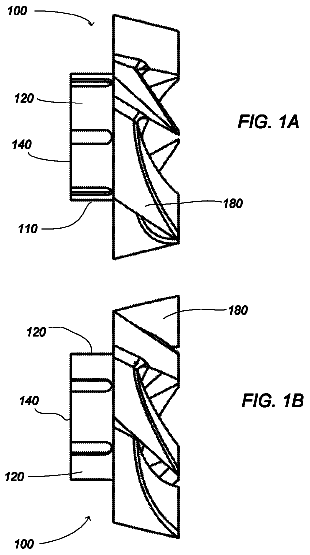
Fastening nut and tool bit holding system
A fastening nut for fastening a receiving body and a collet together is disclosed.
US 8,700,215 B2 · Assignee: Panasonic Corporation · Inventors: Komatsu; Mayumi et al.
Sheet 1 of 14 from the published document. All sheets in the USPTO PDF
An inner pressure of an actuator is measured by a pressure measuring unit, and an amount of displacement of a movable mechanism is measured so that a position error compensation unit to which a desired value for the displacement and the measured value are inputted is allowed to compensate for a position error, and a desired value for a pressure difference of actuators that are competitively driven from the desired value is calculated by a desired pressure difference calculation unit, and an adjusted correcting value of the desired value for the pressure difference, obtained from the desired value of displacement and the measured value, is adjustably outputted from an adjustable desired inner-state correction unit, and thus, the outputs of these unit are inputted to a pressure difference error compensation unit so that a pressure difference error is compensated therewith.
In recent years, developments of house-service robots such as pet robots or the like have been vigorously carried out, and it has been expected that in the future, more practical house-service robots, such as house-keeping support robots and the like, will be put into practical use. Since the house-service robot is used in a home, and needs to live together with people, its required specifications are made different from those of a conventional industrial robot. In the case of the industrial robot, electric motors or speed reducers are used, and a high hand position precision, such as a repetitive precision of 0.1 mm or the like, has been achieved by a feed-back controlling operation with a high gain. However, such a mechanism driven by electric motors is high in rigidity, and tends to lack flexibility in most cases, resulting in an issue with safety. In contrast, in the case of the hous
8 of 14 drawing sheets so far from the published document, cropped to the drawing. Every sheet is in the USPTO PDF.
What the patent claimed, word for word. All of it is now free to use.
The present invention relates to an apparatus and method that control operations of an elastic body actuator driven by deformation of an elastic member, such as a fluid-pressure driving actuator and the like, and also relates to a control program thereof.
In recent years, developments of house-service robots such as pet robots or the like have been vigorously carried out, and it has been expected that in the future, more practical house-service robots, such as house-keeping support robots and the like, will be put into practical use. Since the house-service robot is used in a home, and needs to live together with people, its required specifications are made different from those of a conventional industrial robot.
In the case of the industrial robot, electric motors or speed reducers are used, and a high hand position precision, such as a repetitive precision of 0.1 mm or the like, has been achieved by a feed-back controlling operation with a high gain. However, such a mechanism driven by electric motors is high in rigidity, and tends to lack flexibility in most cases, resulting in an issue with safety.
In contrast, in the case of the house-service robot, such high precision with a repetitive precision of 0.1 mm or the like is not necessarily required, and more emphasis is placed on safety, that is, on such a characteristic as not to cause damage even in contact with a person. Therefore, the mechanism to be driven by electric motors, such as that of a conventional industrial robot, is not considered to be suitable for the field in which more emphasis is placed on safety, such as the field of the house-service robots, and flexible and safe robot arms are required.
In view of these issues, for example, a robot arm which utilizes a pneumatic actuator of McKibben type has been proposed. The McKibben type pneumatic actuator has a structure in which regulating means formed by fiber cords is placed on an outer surface of a tube-shaped elastic member made of a rubber material, with the two ends of the tube-shaped elastic member being air-tightly sealed with a sealing member. When an inner pressure is applied to the inner space of the tube-shaped elastic member by a compressive fluid such as air through fluid injection and discharge means, the tube-shaped elastic member tries to expand mainly in a radial direction; however, the expansion is converted to a motion in a center axis direction of the tube-shaped elastic member by the regulating means so that the overall length thereof is contracted. Since the actuator of the McKibben type is mainly composed of an elastic member, it is flexible and makes it possible to form a safe actuator having a light weight.
However, the fluid-pressure drive actuator, such as the actuator of the McKibben type, which is operated by a fluid pressure such as air, is poor in response characteristic due to influences of elastic characteristics caused by the compressive fluid, flow passage resistance, or the like. For this reason, the elastic body actuator has issues in that, for example, it is not possible to achieve a desired precision by using a conventional generally-used feed-back controlling operation.
In view of these issues, as a conventional technique, a control device has been disclosed (Patent Document 1) in which inner-state error compensation means is installed so that a control system for feeding back the inner state of the elastic body actuator is prepared, and desired inner-state determination means is also installed so that a control system for feeding forward a desired inner state is prepared; thus, the resulting control device makes it possible to carry out a high-speed controlling operation with high precision, and improved responsiveness, with little stationary error.
Patent Document
Patent Document 1: JP-A No. 2005-95989
Issues to be Resolved by the Invention
In the desired inner-state determination means, however, since the results, obtained by carrying out preliminary experiments to measure a relationship between the output and the inner state, are expressed by an approximation polynomial equation or the like, the desired inner state cannot be altered in response to a change other than fluctuation parameters preliminarily presumed. For this reason, under complicated circumstances in which it is difficult to preliminarily presume all the environments, as in the case of the house-service robot, an issue arises in that the relationship between the output and the inner state becomes different from a preliminarily presumed environment, resulting in poor precision.
An object of the present invention is to resolve the above conventional issues, and to provide a control apparatus and a control method for an elastic body actuator, as well as a control program thereof, which can control a position or a force of a movable mechanism such as a robot arm driven by the elastic body actuator with high precision, even under an environment other than preliminarily presumed environments.
Means for Resolving the Issues
In order to solve the above conventional issues, the present invention has the following structures:
According to a first aspect of the present invention, there is provided a control apparatus for an elastic body actuator comprising:
an inner-state measuring unit that measures an inner state of the elastic body actuator;
an output measuring unit that measures an output of the elastic body actuator;
an output error compensation unit to which a desired value of the output of the elastic body actuator and a measured value of the output of the elastic body actuator measured by the output measuring unit are inputted so as to compensate for an output error;
a desired inner-state determination unit that determines a desired value of the inner state of the elastic body actuator based on the desired value of the output of the elastic body actuator;
an adjustable desired inner-state correction unit that, when an error occurs between the desired value of the output of the elastic body actuator and the measured value of the output of the elastic body actuator, determines a desired correcting value of the inner-state so as to make the error smaller; and
an inner-state error compensation unit that allows an output from the output error compensation unit, a desired value for the inner-state outputted from the desired inner-state determination unit, a desired correcting value for the inner-state outputted from the adjustable desired inner-state correction unit, and an output from the inner-state measuring unit to be inputted therein so that an inner-state error is compensated, wherein
based on the inner-state error that has been compensated for by the inner-state error compensation unit, the measured value of the output of the elastic body actuator is controlled to be set to the desired value of the output.
With this arrangement, it becomes possible to achieve control of an elastic body actuator that can control the position or force with high precision, even under an environment other than preliminarily presumed environments.
According to a thirteenth aspect of the present invention, there is provided a method for controlling an elastic body actuator, comprising:
measuring an inner state of the elastic body actuator with an inner-state measuring unit;
measuring an output of the elastic body actuator with an output measuring unit;
compensating an output error with an output error compensation unit by inputting a desired value of the output of the elastic body actuator and a measured value of the output of the elastic body actuator measured by the output measuring unit;
determining a desired value of the inner state of the elastic body actuator based on the desired value of the output of the elastic body actuator with a desired inner-state determination unit;
determining with an adjustable desired inner-state correction unit, when an error occurs between the desired value of the output of the elastic body actuator and the measured value of the output of the elastic body actuator, a desired correcting value of the inner state so as to make the error smaller; and
compensating an inner-state error with an inner-state error compensation unit by inputting therein an output from the output error compensation unit, a desired value for the inner state outputted from the desired inner-state determination unit, a desired correcting value for the inner state outputted from the adjustable desired inner-state correction unit, and an output from the inner-state measuring unit, wherein
the method comprising, based on the inner-state error that has been compensated for by the inner-state error compensation unit, controlling the measured value of the output of the elastic body actuator to be set to the desired value of the output.
With this arrangement, it becomes possible to achieve control of an elastic body actuator that can control the position or force with high precision, even under an environment other than preliminarily presumed environments.
According to a fourteenth aspect of the present invention, there is provided a program for a control apparatus for an elastic body actuator, allowing a computer to function as:
an output error compensation unit to which a desired value of the output of the elastic body actuator and a measured value of the output of the elastic body actuator measured by an output measuring unit that measures the measured value of the output of the elastic body actuator are inputted so as to compensate for an output error;
a desired inner-state determination unit that determines a desired value of an inner state of the elastic body actuator based on the desired value of the output of the elastic body actuator;
an adjustable desired inner-state correction unit that, when an error occurs between the desired value of the output of the elastic body actuator and the measured value of the output of the elastic body actuator, determines a desired correcting value of the inner state so as to make the error smaller; and
an inner-state error compensation unit that allows an output from the output error compensation unit, a desired value for the inner-state outputted from the desired inner-state determination unit, a desired correcting value for the inner-state outputted from the adjustable desired inner-state correction unit, and an output from the inner-state measuring unit that measures the inner state of the elastic body actuator to be inputted therein so that an inner-state error is compensated, wherein
based on the inner-state error that has been compensated for by the inner-state error compensation unit, the measured value of the output of the elastic body actuator is controlled to be set to the desired value of the output.
With this arrangement, it becomes possible to achieve control of an elastic body actuator that can control the position or force with high precision, even under an environment other than preliminarily presumed environments.
Effects of the Invention
According to a control apparatus and a control method for an elastic body actuator of the present invention, as well as a control program thereof, since the inner-state error compensation unit is installed to form a control system for feeding back the inner state of the elastic body actuator and since the desired inner-state determination unit and the adjustable desired inner-state correction unit are also installed to form a control system for feeding forward an adjustably corrected desired inner-state, it becomes possible to provide a high-speed controlling operation with high precision that is superior in response characteristic, with little stationary error.
These and other objects and features of the present invention will become clear from the following description taken in conjunction with preferred embodiments thereof with reference to the accompanying drawings, in which:
FIG. 1 is a block diagram showing a concept of a control apparatus for an elastic body actuator according to a first embodiment of the present invention;
FIG. 2 is a view showing a structure of a robot arm that is a subject to be controlled by the control apparatus for the elastic body actuator according to the first embodiment of the present invention;
FIG. 3 is a view showing a structure and operations of an elastic expansion/contraction structural member for driving the robot arm to be controlled by the control apparatus for the elastic body actuator according to the first embodiment of the present invention;
FIG. 4 is a view showing operations of an air pressure supply system for driving the robot arm to be controlled by the control apparatus for the elastic body actuator according to the first embodiment of the present invention by using air serving as a compressive fluid;
FIG. 5 is a control block diagram of the control apparatus for the elastic body actuator according to the first embodiment of the present invention;
FIG. 6 is a view showing a structure for calculating a desired pressure difference in the first embodiment of the present invention;
FIG. 7 is a flow chart showing actual operation steps of a control program in the control apparatus for the elastic body actuator according to the first embodiment of the present invention;
FIG. 8 is a view showing a structure of an adjustable desired pressure difference correction means of a control apparatus for the elastic body actuator according to a second embodiment of the present invention;
FIG. 9A is a view showing results of operations when a track following control operation of a hand position is carried out on the robot arm shown in FIG. 2, by a conventional control apparatus that uses only a desired pressure difference calculation means shown in FIG. 6, without using an adjustable desired inner-state correction means;
FIG. 9B is a view showing results of operations when a track following control operation of a hand position is carried out by using the control apparatus for the elastic body actuator according to the first embodiment of the present invention shown in FIG. 5;
FIG. 10 is a control block diagram showing a structure which uses a conductive polymer actuator serving as one example of the elastic body actuator control apparatus according to the first embodiment of the present invention;
FIG. 11A is a view showing a structure and operations of the conductive polymer actuator for driving a robot arm serving as a subject to be controlled by the control apparatus for the elastic body actuator according to the first embodiment of the present invention;
FIG. 11B is a view showing a structure and operations of the conductive polymer actuator for driving a robot arm serving as a subject to be controlled by the control apparatus for the elastic body actuator according to the first embodiment of the present invention;
FIG. 11C is a view showing a structure and operations of the conductive polymer actuator for driving a robot arm serving as a subject to be controlled by the control apparatus for the elastic body actuator according to the first embodiment of the present invention;
FIG. 12 is a control block diagram showing an elastic body actuator control apparatus according to a third embodiment of the present invention; and
FIG. 13 is a flow chart showing operation steps of a control program based on the elastic body actuator control apparatus according to the first embodiment of the present invention.
With reference to the drawings, the following description will discuss embodiments of the present invention in detail.
Prior to describing the embodiments of the present invention, various modes of the present invention will be described.
According to a first aspect of the present invention, there is provided a control apparatus for an elastic body actuator comprising:
an inner-state measuring unit that measures an inner state of the elastic body actuator;
an output measuring unit that measures an output of the elastic body actuator;
an output error compensation unit to which a desired value of the output of the elastic body actuator and a measured value of the output of the elastic body actuator measured by the output measuring unit are inputted so as to compensate for an output error;
a desired inner-state determination unit that determines a desired value of the inner-state of the elastic body actuator based on the desired value of the output of the elastic body actuator;
an adjustable desired inner-state correction unit that, when an error occurs between the desired value of the output of the elastic body actuator and the measured value of the output of the elastic body actuator, determines a desired correcting value of the inner-state so as to make the error smaller; and
an inner-state error compensation unit that allows an output from the output error compensation unit, a desired value for the inner-state outputted from the desired inner-state determination unit, a desired correcting value for the inner-state outputted from the adjustable desired inner-state correction unit, and an output from the inner-state measuring unit to be inputted therein so that the inner-state error is compensated, wherein
based on the inner-state error that has been compensated for by the inner-state error compensation unit, the measured value of the output of the elastic body actuator is controlled to be set to the desired value of the output.
According to a second aspect of the present invention, there is provided the control apparatus for an elastic body actuator according to the first aspect, wherein the desired inner-state determination unit further acquires a measured value of an output of the elastic body actuator, and determines a desired value of the inner state of the elastic body actuator based on the desired value of the output of the elastic body actuator and the measured value of the output of the elastic body actuator.
According to a third aspect of the present invention, there is provided the control apparatus for an elastic body actuator according to the first or second aspect, further comprising:
an addition unit that adds the output of the desired inner-state determination unit to the output of the adjustable desired inner-state correction unit, and outputs the resulting value of the addition to the inner-state error compensation unit.
According to a fourth aspect of the present invention, there is provided the control apparatus for an elastic body actuator according to any one of the first to third aspects, wherein the adjustable desired inner-state correction unit calculates an adjusted offset value obtained by integrating a value obtained by multiplying a value prepared by subtracting an output value from the desired value of the output by a gain, and an adjusted gain value obtained by integrating a value obtained by multiplying a value obtained by multiplying a value prepared by subtracting an initial value from the desired value of the output by a value prepared by subtracting the output value from the desired value of the output, by a gain, so that a value obtained by adding a value prepared by multiplying the adjusted gain value by the desired value of the output to the adjusted offset value is set to a desired correcting value of the inner state.
According to a fifth aspect of the present invention, there is provided the control apparatus for an elastic body actuator according to any one of the first to fourth aspects, wherein the adjustable desired inner-state correction unit further comprises a reference model so that, when an error occurs among the output desired value, an output of the reference model and the output of the elastic body actuator, values, obtained by multiplying the desired value of the output and a state variable of the reference model by a gain that makes the error smaller, are added to each other so as to be set as a desired correcting value of the inner state.
According to a sixth aspect of the present invention, there is provided the control apparatus for an elastic body actuator according to any one of the first to fifth aspects, further comprising:
a correcting output control unit that carries out a switching operation among a state in which the adjustable desired inner-state correction unit is used, a state in which no adjustable desired inner-state correction unit is used, and a state in which an update of the output from the adjustable desired inner-state correction unit is stopped.
According to a seventh aspect of the present invention, there is provided the control apparatus for an elastic body actuator according to any one of the first to sixth aspects, further comprising:
a correcting output control unit that carries out a switching operation between a state that allows the output from the adjustable desired inner-state correction unit to pass through a low-pass filter and a state that does not allow the output to pass therethrough.
According to an eighth aspect of the present invention, there is provided the control apparatus for an elastic body actuator according to the sixth aspect, wherein the adjustable desired inner-state correction unit further comprises:
a determination unit that receives a repetition signal from the desired track generation unit by the adjustable desired inner-state correction unit, and when the determination unit has determined that tracks of the elastic body actuator, obtained when desired values of the elastic body actuator are time-sequentially aligned, are repetitive, determines to use the adjustable desired inner-state correction unit.
According to a ninth aspect of the present invention, there is provided the control apparatus for an elastic body actuator according to the eighth aspect, wherein upon using the adjustable desired inner-state correction unit, the correcting output control unit determines to stop updating the output of the adjustable desired inner-state correction unit, when the elastic body actuator has an output error that is smaller than a predetermined threshold value.
According to a tenth aspect of the present invention, there is provided the control apparatus for an elastic body actuator according to the sixth aspect, wherein the correcting output control unit comprises a collision detection unit that detects a fact that the elastic body actuator has collided with an object so that, upon detection of the collision by the collision detection unit, the correcting output control unit determines to stop updating the output of the adjustable desired inner-state correction unit.
According to an eleventh aspect of the present invention, there is provided the control apparatus for an elastic body actuator according to the sixth aspect, wherein the correcting output control unit determines not to use the adjustable desired inner-state correction unit when starting the elastic body actuator.
According to a twelfth aspect of the present invention, there is provided the control apparatus for an elastic body actuator according to the sixth aspect, wherein the correcting output control unit further comprises a low-pass filter that allows the output to pass therethrough for a predetermined period of time, when a state where the adjustable desired inner-state correction unit is not used is switched to a state where the adjustable desired inner-state correction unit is used, or when a state where the output of the adjustable desired inner-state correction unit is stopped without being updated is switched to a state where the output thereof is updated.
According to a thirteenth aspect of the present invention, there is provided a method for controlling an elastic body actuator, comprising:
measuring an inner state of the elastic body actuator with an inner-state measuring unit;
measuring an output of the elastic body actuator with an output measuring unit;
compensating an output error with an output error compensation unit by inputting a desired value of the output of the elastic body actuator and a measured value of the output of the elastic body actuator measured by the output measuring unit;
determining a desired value of the inner state of the elastic body actuator based on the desired value of the output of the elastic body actuator with a desired inner-state determination unit;
determining with an adjustable desired inner-state correction unit, when an error occurs between the desired value of the output of the elastic body actuator and the measured value of the output of the elastic body actuator, a desired correcting value of the inner state so as to make the error smaller; and
compensating an inner-state error with an inner-state error compensation unit by inputting therein an output from the output error compensation unit, a desired value for the inner state outputted from the desired inner-state determination unit, a desired correcting value for the inner state outputted from the adjustable desired inner-state correction unit, and an output from the inner-state measuring unit, wherein
the method comprising, based on the inner-state error that has been compensated for by the inner-state error compensation unit, controlling the measured value of the output of the elastic body actuator to be set to the desired value of the output.
According to a fourteenth aspect of the present invention, there is provided a program for a control apparatus for an elastic body actuator, allowing a computer to function as:
an output error compensation unit to which a desired value of an output of the elastic body actuator and a measured value of the output of the elastic body actuator measured by an output measuring unit that measures the measured value of the output of the elastic body actuator are inputted so as to compensate for an output error;
a desired inner-state determination unit that determines a desired value of the inner state of the elastic body actuator based on the desired value of the output of the elastic body actuator;
an adjustable desired inner-state correction unit that, when an error occurs between the desired value of the output of the elastic body actuator and the measured value of the output of the elastic body actuator, determines a desired correcting value of the inner state so as to make the error smaller; and
an inner-state error compensation unit that allows an output from the output error compensation unit, a desired value for the inner state outputted from the desired inner-state determination unit, a desired correcting value for the inner state outputted from the adjustable desired inner-state correction unit, and an output from inner-state measuring unit that measures the inner state of the elastic body actuator to be inputted therein so that an inner-state error is compensated, wherein
based on the inner-state error that has been compensated for by the inner-state error compensation unit, the measured value of the output of the elastic body actuator is controlled to be set to the desired value of the output.
With reference to the drawings, the following description will discuss embodiments of the present invention in detail.
(First Embodiment)
FIG. 1 is a block diagram showing a concept of a control apparatus for an elastic body actuator according to a first embodiment of the present invention. In FIG. 1, an elastic body actuator 102 is a fluid-pressure drive actuator that is driven by a fluid pressure.
The control apparatus for the elastic body actuator 102 is provided with a desired output generation means 101, an output measuring means 104, a desired inner-state determination means 105, an output error compensation means 103, an adjustable desired inner-state correction means 111, an inner-state measuring means 107, an inner-state error compensation means 106, and an output error calculation unit 108.
The desired output generation means 101 generates a desired value 113 of an output from each of the elastic body actuators 102.
The output measuring means 104, which is connected to the respective elastic body actuators 102, measures the output of each elastic body actuator 102, and inputs a measured value 112 to the output error compensation means 103 and the adjustable desired inner-state correction means 111 respectively, through the desired inner-state determination means 105 and the output error calculation unit 108.
The output error calculation unit 108 calculates an output error 114 based on the output desired value 113 from the desired output generation means 101 and the output (calculated value 112) from the output measuring means 104, and outputs the calculated result to the output error compensation means 103.
The output error compensation means 103 corrects the output error 114 inputted from the output error calculation unit 108 to the output error compensation means 103 so as to be made smaller, and controls the measured value 112 measured by the output measuring means 104 so as to follow the output desired value 113 from the desired output generation means 101.
The desired inner-state determination means 105 to which the output desired value 113 of the desired output generation means 101 and the measured value 112 from the output measuring means 104 have been inputted determines an inner-state desired value 116 of each of the elastic body actuators 102 based on the output desired value 113 and the measured value 112.
The adjustable desired inner-state correction means 111 to which the output desired value 113 from the desired output generation means 101 and the measured value 112 from the output measuring means 104 have been inputted carries out a signal processing operation by using an adjustable algorithm based on the output desired value 113 and the measured value 112, and determines an inner-state desired correcting value 117 of each of the elastic body actuators 102. More specifically, based on the desired value of the output of each of the elastic body actuators 102 and the measured value of the output of each of the elastic body actuators 102, when an error is generated between the inner state of the elastic body actuator 102 and the output of the elastic body actuator 102, the adjustable desired inner-state correction means 111 carries out a signal combining operation so as to make the error smaller so that the resulting signal is determined as the desired correcting value 117 of the inner state. An inner-state error calculation unit 109, which serves as one example of an addition unit, calculates an inner-state error based on an output 115 from the output error compensation means 103, the output (inner-state desired value) 116 from the desired inner-state determination means 105, the output (inner-state desired correcting value) 117 from the adjustable desired inner-state correction means 111, and an output (inner-state measured value) 118 from the inner-state measuring means 107, and outputs the resulting value to the inner-state error compensation means 106.
Upon receipt of the output from the output error compensation means 103, the output from the desired inner-state determination means 105, the output from the adjustable desired inner-state correction means 111, and the output from the inner-state error calculation unit 109, the inner-state error compensation means 106 carries out a controlling operation so as to compensate for the inner-state error, that is, so as to allow the inner-state measured value of each of the elastic body actuators 102 to follow the desired value.
The inner-state measuring means 107, which is connected to each of the elastic body actuators 102, measures an inner-state measured value 118 that corresponds to an inner pressure of each of elastic expansion/contraction structural members 1, which will be described later, in each of the elastic body actuators 102, and inputs the measured value to the inner-state error calculation unit 109.
With reference to a flow chart of FIG. 13, the following description will discuss actual operation steps of a control program formed based on the above-mentioned principle.
In step S101, the measured value of the output of each elastic body actuator 102, measured by the output measuring means 104, is received by the control apparatus.
Next, in step S102, based on an operation program of each elastic body actuator 102, preliminarily stored in the desired output generation means 101, the desired output generation means 101 calculates an output desired value of the elastic body actuator 102.
Next, in step S103, the output error calculation unit 108 calculates an output error that is a difference between the output desired value calculated by the desired output generation means 101 and the measured value of the current output measured by the output measuring means 104.
Next, in step S104, the output error compensation means 103 calculates an output error correction output from the output error calculated by the output error calculation unit 108.
Next, in step S105, based on the output desired value calculated in the desired output generation means 101 and the measured value of the current output measured by the output measuring means 104, the desired inner-state determination means 105 calculates an inner-state desired value.
Next, in step S106, based on the output desired value calculated in the desired output generation means 101 and the measured value of the current output measured by the output measuring means 104, the adjustable desired inner-state correction means 111 calculates an adjustable desired inner-state correction value.
Next, in step S107, the measured value of the inner state of the elastic body actuator 102, measured by the inner-state measuring means 107, is received by the control apparatus.
Next, in step S108, by subtracting the measured value of the inner state measured in step S107 from a value obtained by adding the output error correction output calculated by the output error compensation means 103 in step S104, the inner-state desired value calculated by the desired inner-state determination means 105 in step S105, and the adjustable desired inner-state correcting value calculated in the adjustable desired inner-state correction means 111 in step S106 to one another, the inner-state error calculation unit 109 calculates an inner-state error.
Next, in step S109, based on the inner-state error calculated by the inner-state error calculation unit 109, the inner-state error compensation means 106 calculates an inner-state error correction output.
Next, in step S110, the inner-state error correction output calculated by the inner-state error compensation means 106 is given from the inner-state error compensation means 106 to the elastic body actuator 102 so that elastic body actuator 102 is driven.
By repeatedly executing the above steps S101 to S110 as a controlling calculation loop, the control of the elastic body actuator 102 is realized.
Next, the following description will discuss a specific example of the control apparatus of the elastic body actuator 102 of the first embodiment, by exemplifying a robot arm 10 as a control subject.
FIG. 2 is a view showing a structure of the robot arm 10 serving as the subject to be controlled by the control apparatus of the elastic body actuator 102 according to the first embodiment of the present invention. The robot arm 10 is a robot arm of two degrees of freedom, and provided with a first joint axis 6-1 that is allowed to forwardly and reversely rotate on an xy plane including an x-axis and a y-axis that are orthogonal to each other and a second joint axis 6-2 that is allowed to forwardly and reversely rotate on the xy plane in the same manner.
In FIG. 2, reference numerals, 1-1a, 1-1b, 1-2a, and 1-2b (which are reference numerals indicating elastic expansion/contraction structural members individually, and when the elastic expansion/contraction structural member is typically represented, reference numeral 1 is used), represent elastic expansion/contraction structural members. As shown in FIG. 3, the elastic expansion/contraction structural member 1 has a structure in which a deforming direction regulating member 3, made of fiber codes of resin or metal that are hardly extendable material and knitted into a network pattern, is disposed on an outer surface of a tube-shaped hollow elastic member 2 composed of a rubber material and functions as a driving unit. The deforming direction regulating member 3 is designed so that a deformation in a radial direction by an expansion of the tube-shaped elastic member 2 is converted to a contraction in length in the axial direction, while a deformation in a radial direction by a contraction of the tube-shaped elastic member 2 is converted to an expansion in length in the axial direction. Each of the two ends of the tube-shaped elastic member 2 is air-tightly sealed by a sealing member 4. A tube-shaped fluid transmitting member 5 provided in the sealing member 4 has a flow passage for fluid through which a compressible fluid is allowed to pass, formed therein, so that a fluid can be injected or discharged to or from the hollow inner space of the hollow elastic member 2. A compressible fluid, such as air, is supplied to the hollow tube-shaped elastic member 2 through the fluid transmitting member 5.
When an inner pressure is applied to the inner space of the tube-shaped elastic member 2 by the compressible fluid supplied thereto, the tube-shaped elastic member 2 tends to expand mainly in the radial direction. However, by the function of the deforming direction regulating member 3, the movement is converted into motion in the center axis direction of the tube-shaped elastic member 2 so that, since the overall length is contracted, it can be utilized as a direct-driven elastic body actuator 102.
In the robot arm 10, a pair of elastic expansion/contraction structural members (1, 1) is disposed so as to allow the joint axis 6-1 or 6-2 to face its fulcrum. Of the paired elastic expansion/contraction structural members (1, 1), either one of the elastic expansion/contraction structural members 1 is contracted, with the other elastic expansion/contraction structural member 1 is expanded. Thus, a competitive driving structure in which forces are exerted through the fulcrum to rotate the axis is formed so that forward and reverse rotation movements of the joint axis 6-1 or 6-2 are realized. More specifically, by the competitive driving operations of the elastic expansion/contraction structural member 1-1a and the elastic expansion/contraction structural member 1-1b, the first joint axis 6-1 is allowed to forwardly and reversely rotate. By the competitive driving operations of the elastic expansion/contraction structural member 1-2a and the elastic expansion/contraction structural member 1-2b, the second joint axis 6-2 is allowed to forwardly and reversely rotate.
Two round supporting members 302, 302 are supported on two sides of an upper end of a supporting axis (second axis) 303 concentrically with the first joint axis 6-1 so as to freely rotate thereon. On a fixed base 301 side of the lower end of the supporting axis 303, supporting members 307, 307 are secured in a direction orthogonal to the longitudinal direction of the supporting axis 303. The elastic expansion/contraction structural members 1-1a and 1-1b are coupled to each other between the two round supporting members 302, 302 and the supporting members 307, 307. Consequently, by the competitive driving operations of the elastic expansion/contraction structural members 1-1a and 1-1b, the two round supporting members 302, 302 are allowed to forwardly and reversely rotate within the xy plane around the axis of the supporting axis 314 of the first joint axis 6-1. As a result, a first arm 311 of the robot arm 10 coupled to the two round supporting members 302, 302 and a driving axis 313 can be forwardly and reversely rotated integrally.
The description continues in the full USPTO document.
About 6,421 words. The USPTO PDF has it with every drawing.
Fees are due 3.5, 7.5 and 11.5 years after grant. This patent expired on April 15, 2026, so the fee marked "not paid" was the one that went unpaid.
CONTROL APPARATUS AND CONTROL METHOD OF ELASTIC BODY ACTUATOR AS WELL AS CONTROL PROGRAM THEREOF
Filed Jan 2010 · published Mar 2011Control apparatus and control method of elastic body actuator as well as control program thereof
Filed Jan 2010 · granted Apr 2014Earlier publications, parents and continuations. None of them can still be enforced, or this patent would not be listed.
Prior art cited by the examiner or applicant. Useful when you check your own idea for novelty.
Everything on this page comes from the documents linked above.


