Field
The present invention relates generally to wireless communications, and more specifically to a novel and improved method and apparatus for congestion control in a wireless data network.
Background
Wireless communication systems are widely deployed to provide various types of communication such as voice and data. These systems may be based on code division multiple access (CDMA), time division multiple access (TDMA), or some other multiple access techniques. A CDMA system provides certain advantages over other types of systems, including increased system capacity.
A CDMA system may be designed to support one or more CDMA standards such as
the "TIA/EIA-95-B Mobile Station-Base Station Compatibility Standard for Dual-Mode Wideband Spread Spectrum Cellular System" (the IS-95 standard),
the standard offered by a consortium named "3rd Generation Partnership Project" (3GPP) and embodied in a set of documents including Document Nos. 3G TS 25.211, 3G TS 25.212, 3G TS 25.213, and 3G TS 25.214 (the W-CDMA standard),
the standard offered by a consortium named "3rd Generation Partnership Project 2" (3GPP2) and embodied in "TR-45.5 Physical Layer Standard for cdma2000 Spread Spectrum Systems" (the IS-2000 standard), and
some other standards.
In the above named standards, the available spectrum is shared simultaneously among a number of users, and techniques such as power control and soft handoff are employed to maintain sufficient quality to support delay-sensitive services, such as voice. Data services are also available. More recently, systems have been proposed that enhance the capacity for data services by using higher order modulation, very fast feedback of Carrier to Interference ratio (C/I) from the mobile station, very fast scheduling, and scheduling for services that have more relaxed delay requirements. An example of such a data-only communication system using these techniques is the high data rate (HDR) system that conforms to the TIA/EIA/IS-856 standard (the IS-856 standard).
In contrast to the other above named standards, an IS-856 system uses the entire spectrum available in each cell to transmit data to a single user at one time, selected based on link quality. In so doing, the system spends a greater percentage of time sending data at higher rates when the channel is good, and thereby reduces committing resources to support transmission at inefficient rates. The net effect is higher data capacity, higher peak data rates, and higher average system throughput.
Systems can incorporate support for delay-sensitive data, such as voice channels or data channels supported in the IS-2000 standard, along with support for packet data services such as those described in the IS-856 standard. The cdma2000.RTM. Revision C of the IS-2000 standard (including C.S0001.C through C.S0006.C) is such a system, and is hereinafter referred to as the 1xEV-DV system. In the rest of the document, we'll refer to release 0, A, and B of the cdma2000.RTM. standard as cdma2000, while revision C and upwards will be referred to as 1xEV-DV systems.
An example 1xEV-DV system includes a reverse link control mechanism for allocating the shared reverse link resource for transmission by a plurality of mobile stations. A mobile station may make a request to a serving base station for transmission permission with a maximum rate supportable by the mobile station. Alternatively, a mobile station is allowed to transmit autonomously, without making a request, at a rate up to a determined autonomous maximum rate. The serving base station anticipates an expected amount of autonomous transmission on the reverse link, reviews any requests made by mobile stations, and allocates the shared resource accordingly. The base station may elect to make one or more individual grants to requesting mobile stations, and includes the maximum rate for those grants. The remaining requesting mobile stations may be issued permission to transmit according to a common grant, with an associated maximum transmission rate. Thus, the serving base station attempts to maximize utilization of the shared resource with a combination of individual and common grants, in the presence of autonomous transmission by other mobile stations. Various techniques may be used to allow mobile stations to continue transmitting according to a determined allocation and the associated grants, with a minimum amount of signaling required.
From time to time, the amount of loading on the reverse link may exceed the amount predicted by the serving base station. Various factors may lead to this system over-utilization, an example of which is the uncertainty in the actual number of autonomous transmissions that may transpire. Overall throughput, and thus effective capacity of the system, may deteriorate when the system becomes congested. For example, a resultant increase in error rate may result in loss of successful data transmission, and subsequent retransmission will use additional capacity on the shared resource. While the allocation and granting procedure just described may be used to alleviate overloading on the system, there is latency associated with the messaging required. Capacity and throughput may be adversely affected during this time. It is desirable to be able to reduce the system loading quickly to minimize these adverse effects.
Furthermore, additional messaging also uses system capacity. In some circumstances, the system overload is a temporal condition, after which, the previous allocation and associated grants will be appropriate for the desired system load. It is desirable for the various mobile stations to return to the prescribed allocation while minimizing messaging overhead. There is therefore a need in the art for congestion control to reduce system loading efficiently.
Summary
Embodiments disclosed herein address the need for congestion control. In one embodiment, a base station allocates a shared resource using a combination of zero or more individual grants and zero or more common grants, and generates a busy signal in response to loading conditions that exceed a pre-determined level. In another embodiment, a subset of transmitting mobile stations reduce their transmission rate in response to a busy signal. In one embodiment, autonomously transmitting mobile stations adjust transmission rates in response to a busy signal. In another embodiment, commonly granted mobile stations adjust transmission rates in response to a busy signal. In yet another embodiment, individually granted mobile stations adjust transmission rates in response to a busy signal. In various embodiments, rate adjustment may be probabilistic or deterministic. In one embodiment, a rate table is deployed, and a mobile station decreases or increases the transmission rate from one rate in the table to a lower or higher rate in the table, respectively, in response to the busy signal. Various other aspects are also presented. These aspects have the benefit of providing efficient utilization of the reverse link capacity, accommodating varying requirements such as low-latency, high throughput or differing quality of service, and reducing forward and reverse link overhead for providing these benefits, thus avoiding excessive interference and increasing capacity.
The invention provides methods and system elements that implement various aspects, embodiments, and features of the invention, as described in further detail below.
Brief description of the drawings
The features, nature, and advantages of the present invention will become more apparent from the detailed description set forth below when taken in conjunction with the drawings in which like reference characters identify correspondingly throughout and wherein:
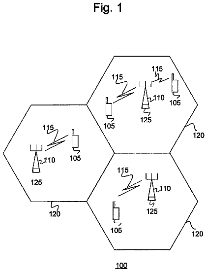
FIG. 1 is a general block diagram of a wireless communication system capable of supporting a number of users;
FIG. 2 depicts an example mobile station and base station configured in a system adapted for data communication;
FIG. 3 is a block diagram of a wireless communication device, such as a mobile station or base station;
FIG. 4 depicts an exemplary embodiment of data and control signals for reverse link data communication;
FIG. 5 contrasts the R-ESCH power level with and without fast control;
FIG. 6 depicts a method of congestion control that may be performed in a base station;
FIG. 7 depicts a generalized method of congestion control performed at a mobile station;
FIG. 8 depicts a method of congestion control with set rate limits;
FIG. 9 depicts a method of congestion control using a tri-valued busy signal; and
FIG. 10 depicts an embodiment of a rate table that may be deployed with any congestion control method.
Detailed description
FIG. 1 is a diagram of a wireless communication system 100 that may be designed to support one or more CDMA standards and/or designs (e.g., the W-CDMA standard, the IS-95 standard, the cdma2000 standard, the HDR specification, the 1xEV-DV system). In an alternative embodiment, system 100 may additionally support any wireless standard or design other than a CDMA system. In the exemplary embodiment, system 100 is a 1xEV-DV system.
For simplicity, system 100 is shown to include three base stations 104 in communication with two mobile stations 106. The base station and its coverage area are often collectively referred to as a "cell". In IS-95, cdma2000, or 1xEV-DV systems, for example, a cell may include one or more sectors. In the W-CDMA specification, each sector of a base station and the sector's coverage area is referred to as a cell. As used herein, the term base station can be used interchangeably with the terms access point or Node B. The term mobile station can be used interchangeably with the terms user equipment (UE), subscriber unit, subscriber station, access terminal, remote terminal, or other corresponding terms known in the art. The term mobile station encompasses fixed wireless applications.
Depending on the CDMA system being implemented, each mobile station 106 may communicate with one (or possibly more) base stations 104 on the forward link at any given moment, and may communicate with one or more base stations on the reverse link depending on whether or not the mobile station is in soft handoff. The forward link (i.e., downlink) refers to transmission from the base station to the mobile station, and the reverse link (i.e., uplink) refers to transmission from the mobile station to the base station.
While the various embodiments described herein are directed to providing reverse-link or forward-link signals for supporting reverse link transmission, and some may be well suited to the nature of reverse link transmission, those skilled in the art will understand that mobile stations as well as base stations can be equipped to transmit data as described herein and the aspects of the present invention apply in those situations as well. The word "exemplary" is used exclusively herein to mean "serving as an example, instance, or illustration." Any embodiment described herein as "exemplary" is not necessarily to be construed as preferred or advantageous over other embodiments.
1xEV-DV Forward Link Data Transmission and Reverse Link Power Control
A system 100, such as the one described in the 1xEV-DV proposal, generally comprises forward link channels of four classes: overhead channels, dynamically varying IS-95 and IS-2000 channels, a Forward Packet Data Channel (F-PDCH), and some spare channels. The overhead channel assignments vary slowly; for example, they may not change for months. They are typically changed when there are major network configuration changes. The dynamically varying IS-95 and IS-2000 channels are allocated on a per call basis or are used for IS-95, or IS-2000 Release 0 through B packet services. Typically, the available base station power remaining after the overhead channels and dynamically varying channels have been assigned is allocated to the F-PDCH for remaining data services. The F-PDCH may be used for data services that are less sensitive to delay while the IS-2000 channels are used for more delay-sensitive services.
The F-PDCH, similar to the traffic channel in the IS-856 standard, is used to send data at the highest supportable data rate to one user in each cell at a time. In IS-856, the entire power of the base station and the entire space of Walsh functions are available when transmitting data to a mobile station. However, in the proposed 1xEV-DV system, some base station power and some of the Walsh functions are allocated to overhead channels and existing IS-95 and cdma2000 services. The data rate that is supportable depends primarily upon the available power and Walsh codes after the power and Walsh codes for the overhead, IS-95, and IS-2000 channels have been assigned. The data transmitted on the F-PDCH is spread using one or more Walsh codes.
In the 1xEV-DV system, the base station generally transmits to one mobile station on the F-PDCH at a time, although many users may be using packet services in a cell. (It is also possible to transmit to two users by scheduling transmissions for the two users, and allocating power and Walsh channels to each user appropriately.) Mobile stations are selected for forward link transmission based upon some scheduling algorithm.
In a system similar to IS-856 or 1xEV-DV, scheduling is based in part on channel quality feedback from the mobile stations being serviced. For example, in IS-856, mobile stations estimate the quality of the forward link and compute a transmission rate expected to be sustainable for the current conditions. The desired rate from each mobile station is transmitted to the base station. The scheduling algorithm may, for example, select a mobile station for transmission that supports a relatively higher transmission rate in order to make more efficient use of the shared communication channel. As another example, in a 1xEV-DV system, each mobile station transmits a Carrier-to-Interference (C/I) estimate as the channel quality estimate on the Reverse Channel Quality Indicator Channel (R-CQICH). The scheduling algorithm is used to determine the mobile station selected for transmission, as well as the appropriate rate and transmission format in accordance with the channel quality.
As described above, a wireless communication system 100 may support multiple users sharing the communication resource simultaneously, such as an IS-95 system, may allocate the entire communication resource to one user at time, such as an IS-856 system, or may apportion the communication resource to allow both types of access. A 1xEV-DV system is an example of a system that divides the communication resource between both types of access, and dynamically allocates the apportionment according to user demand. Following is a brief background on how the communication resource can be allocated to accommodate various users in both types of access systems. Power control is described for simultaneous access by multiple users, such as IS-95 type channels. Rate determination and scheduling is discussed for time-shared access by multiple users, such as an IS-856 system or the data-only portion of a 1xEV-DV type system (i.e., the F-PDCH).
Capacity in a system such as an IS-95 CDMA system is determined in part by interference generated in transmitting signals to and from various users within the system. A feature of a typical CDMA system is to encode and modulate signals for transmission to or from a mobile station such that the signals are seen as interference by other mobile stations. For example, on the forward link, the quality of the channel between a base station and one mobile station is determined in part by other user interference. To maintain a desired performance level of communication with the mobile station, the transmit power dedicated to that mobile station must be sufficient to overcome the power transmitted to the other mobile stations served by the base station, as well as other disturbances and degradation experienced in that channel. Thus, to increase capacity, it is desirable to transmit the minimum power required to each mobile station served.
In a typical CDMA system, when multiple mobile stations are transmitting to a base station, it is desirable to receive a plurality of mobile station signals at the base station at a normalized power level. Thus, for example, a reverse link power control system may regulate the transmit power from each mobile station such that signals from nearby mobile stations do not overpower signals from farther away mobile stations. As with the forward link, keeping the transmit power of each mobile station at the minimum power level required to maintain the desired performance level allows for capacity to be optimized, in addition to other benefits of power savings such as increased talk and standby times, reduced battery requirements, and the like.
Capacity in a typical CDMA system, such as IS-95, is constrained by, among other things, other-user interference. Other-user interference can be mitigated through use of power control. The overall performance of the system, including capacity, voice quality, data transmission rates and throughput, is dependent upon stations transmitting at the lowest power level to sustain the desired level of performance whenever possible. To accomplish this, various power control techniques are known in the art.
One class of techniques includes closed loop power control. For example, closed loop power control may be deployed on the forward link. Such systems may employ an inner and outer power control loop in the mobile station. An outer loop determines a target received power level according to a desired received error rate. For example, a target frame error rate of 1% may be pre-determined as the desired error rate. The outer loop may update the target received power level at a relatively slow rate, such as once per frame or block. In response, the inner loop then sends up or down power control messages to the base station until received power meets the target. These inner loop power control commands occur relatively frequently, so as to quickly adapt the transmitted power to the level necessary to achieve the desired received signal to noise and interference ratio for efficient communication. As described above, keeping the forward link transmit power for each mobile station at the lowest level reduces other user interference seen at each mobile station and allows remaining available transmit power to be reserved for other purposes. In a system such as IS-95, the remaining available transmit power can be used to support communication with additional users. In a system such as 1xEV-DV, the remaining available transmit power can be used to support additional users, or to increase the throughput of the data-only portion of the system.
In a "data-only" system, such as IS-856, or in the "data-only" portion of a system, such as 1xEV-DV, a control loop may be deployed to govern the transmission from the base station to a mobile station in a time-shared manner. For clarity, in the following discussion, transmission to one mobile station at a time may be described. This is to distinguish from a simultaneous access system, an example of which is IS-95, or various channels in a cdma200 or 1xEV-DV system. Two notes are in order at this point.
First, the term "data-only" or "data channel" may be used to distinguish a channel from IS-95 type voice or data channels (i.e. simultaneous access channels using power control, as described above) for clarity of discussion only. It will be apparent to those of skill in the art that data-only or data channels described herein can be used to transmit data of any type, including voice (e.g., voice over Internet Protocol, or VOIP). The usefulness of any particular embodiment for a particular type of data may be determined in part by the throughput requirements, latency requirements, and the like. Those of skill in the art will readily adapt various embodiments, combining either access type with parameters selected to provide the desired levels of latency, throughput, quality of service, and the like.
Second, a data-only portion of a system, such as that described for 1xEV-DV, which is described as time-sharing the communication resource, can be adapted to provide access on the forward link to more than one user simultaneously. In examples herein where the communication resource is described as time-shared to provide communication with one mobile station or user during a certain period, those of skill in the art will readily adapt those examples to allow for time-shared transmission to or from more than one mobile station or user within that time period.
A typical data communication system may include one or more channels of various types. More specifically, one or more data channels are commonly deployed. It is also common for one or more control channels to be deployed, although in-band control signaling can be included on a data channel. For example, in a 1xEV-DV system, a Forward Packet Data Control Channel (F-PDCCH) and a Forward Packet Data Channel (F-PDCH) are defined for transmission of control and data, respectively, on the forward link.
FIG. 2 depicts an example mobile station 106 and base station 104 configured in a system 100 adapted for data communication. Base station 104 and mobile station 106 are shown communicating on a forward and a reverse link. Mobile station 106 receives forward link signals in receiving subsystem 220. A base station 104 communicating the forward data and control channels, detailed below, may be referred to herein as the serving station for the mobile station 106. An example receiving subsystem is detailed further below with respect to FIG. 3. A Carrier-to-Interference (C/I) estimate is made for the forward link signal received from the serving base station in the mobile station 106. A C/I measurement is an example of a channel quality metric used as a channel estimate, and alternate channel quality metrics can be deployed in alternate embodiments. The C/I measurement is delivered to transmission subsystem 210 in the base station 104, an example of which is detailed further below with respect to FIG. 3.
The transmission subsystem 210 delivers the C/I estimate over the reverse link where it is delivered to the serving base station. Note that, in a soft handoff situation, well known in the art, the reverse link signals transmitted from a mobile station may be received by one or more base stations other than the serving base station, referred to herein as non-serving base stations. Receiving subsystem 230, in base station 104, receives the C/I information from mobile station 106.
Scheduler 240, in base station 104, is used to determine whether and how data should be transmitted to one or more mobile stations within the serving cell's coverage area. Any type of scheduling algorithm can be deployed within the scope of the present invention. One example is disclosed in U.S. patent application Ser. No. 08/798,951, entitled "METHOD AND APPARATUS FOR FORWARD LINK RATE SCHEDULING", filed Feb. 11, 1997, assigned to the assignee of the present invention.
In an example 1xEV-DV embodiment, a mobile station is selected for forward link transmission when the C/I measurement received from that mobile station indicates that data can be transmitted at a certain rate. It is advantageous, in terms of system capacity, to select a target mobile station such that the shared communication resource is always utilized at its maximum supportable rate. Thus, the typical target mobile station selected may be the one with the greatest reported C/I. Other factors may also be incorporated in a scheduling decision. For example, minimum quality of service guarantees may have been made to various users. It may be that a mobile station, with a relatively lower reported C/I, is selected for transmission to maintain a minimum data transfer rate to that user.
In the example 1xEV-DV system, scheduler 240 determines which mobile station to transmit to, and also the data rate, modulation format, and power level for that transmission. In an alternate embodiment, such as an IS-856 system, for example, a supportable rate/modulation format decision can be made at the mobile station, based on channel quality measured at the mobile station, and the transmit format can be transmitted to the serving base station in lieu of the C/I measurement. Those of skill in the art will recognize myriad combinations of supportable rates, modulation formats, power levels, and the like which can be deployed within the scope of the present invention. Furthermore, although in various embodiments described herein the scheduling tasks are performed in the base station, in alternate embodiments, some or all of the scheduling process may take place in the mobile station.
Scheduler 240 directs transmission subsystem 250 to transmit to the selected mobile station on the forward link using the selected rate, modulation format, power level, and the like.
In the example embodiment, messages on the control channel, or F-PDCCH, are transmitted along with data on the data channel, or F-PDCH. The control channel can be used to identify the recipient mobile station of the data on the F-PDCH, as well as identifying other communication parameters useful during the communication session. A mobile station should receive and demodulate data from the F-PDCH when the F-PDCCH indicates that mobile station is the target of the transmission. The mobile station responds on the reverse link following the receipt of such data with a message indicating the success or failure of the transmission. Retransmission techniques, well known in the art, are commonly deployed in data communication systems.
A mobile station may be in communication with more than one base station, a condition known as soft handoff. Soft handoff may include multiple sectors from one base station (or one Base Transceiver Subsystem (BTS)), known as softer handoff, as well as with sectors from multiple BTSs. Base station sectors in soft handoff are generally stored in a mobile station's Active Set. In a simultaneously shared communication resource system, such as IS-95, IS-2000, or the corresponding portion of a 1xEV-DV system, the mobile station may combine forward link signals transmitted from all the sectors in the Active Set. In a data-only system, such as IS-856, or the corresponding portion of a 1xEV-DV system, a mobile station receives a forward link data signal from one base station in the Active Set, the serving base station (determined according to a mobile station selection algorithm, such as those described in the C.S0002.C standard). Other forward link signals, examples of which are detailed further below, may also be received from non-serving base stations.
Reverse link signals from the mobile station may be received at multiple base stations, and the quality of the reverse link is generally maintained for the base stations in the active set. It is possible for reverse link signals received at multiple base stations to be combined. In general, soft combining reverse link signals from non-collocated base stations would require significant network communication bandwidth with very little delay, and so the example systems listed above do not support it. In softer handoff, reverse link signals received at multiple sectors in a single BTS can be combined without network signaling. While any type of reverse link signal combining may be deployed within the scope of the present invention, in the example systems described above, reverse link power control maintains quality such that reverse link frames are successfully decoded at one BTS (switching diversity).
In a simultaneously shared communication resource system, such as IS-95, IS-2000, or the corresponding portion of a 1xEV-DV system, each base station in soft handoff with a mobile station (i.e., in the mobile station's Active Set) measures the reverse link pilot quality of that mobile station and sends out a stream of power control commands. In IS-95 or IS-2000 Rev. B, each stream is punctured onto the Forward Fundamental Channel (F-FCH) or the Forward Dedicated Control Channel (F-DCCH), if either is assigned. The stream of commands for a mobile station is called the Forward Power Control Subchannel (F-PCSCH) for that mobile station. The mobile station receives the parallel command streams from all its Active Set members for each base station (multiple sectors from one BTS, if all in the Active Set of the mobile station, send the same command to that mobile station) and determines if an "up" or "down" command was sent. The mobile station modifies the reverse link transmit power level accordingly, using the "Or-of-downs" rule, that is, the transmit power level is reduced if any "down" command is received, and increased otherwise.
The transmit power level of the F-PCSCH is typically tied to the level of the host F-FCH or F-DCCH that carries the subchannel. The host F-FCH or F-DCCH transmit power level at the base station is determined by the feedback from the mobile station on the Reverse Power Control Subchannel (R-PCSCH), which occupies the last quarter of the Reverse Pilot Channel (R-PICH). Since the F-FCH or the F-DCCH from each base station forms a single stream of traffic channel frames, the R-PCSCH reports the combined decoding results of these legs. Erasures of the F-FCH or the F-DCCH determine the required Eb/Nt set point of the outer loop, which in turn drives the inner loop commands on the R-PCSCH and thus the base station transmit levels of the F-FCH, F-DCCH, as well as the F-PCSCH on them.
Due to the potential differences in reverse link path loss to each base station from a single mobile station in soft handoff, some of the base stations in the Active Set may not receive the R-PCSCH reliably and may not correctly control the forward link power of the F-FCH, F-DCCH, and the F-PCSCH. The base stations may need to re-align the transmit levels among themselves so that the mobile station retains the spatial diversity gain of soft handoff. Otherwise, some of the forward link legs may carry little or no traffic signal energy due to errors in the feedback from the mobile station.
Since different base stations may need different mobile station transmit power for the same reverse link set point or reception quality, the power control commands from different base stations may be different and cannot be soft combined at the MS. When new members are added to the Active Set (i.e. no soft handoff to 1-way soft handoff, or from 1-way to 2-way, etc.), the F-PCSCH transmit power is increased relative to its host F-FCH or F-DCCH.
In a 1xEV-DV system, the Forward Common Power Control Channel (F-CPCCH) transports the reverse link power control commands for mobile stations when neither the Forward Fundamental Channel (F-FCH) nor the Forward Dedicated Control Channel (F-DCCH) are assigned. The serving base station may use the information on the Reverse Channel Quality Indicator Channel (R-CQICH) to determine the transmit power level of the F-CPCCH. The R-CQICH is principally used in scheduling to determine the appropriate forward link transmission format.
However, when the mobile station is in soft handoff, the R-CQICH only reports the forward link pilot quality of the serving base station sector and therefore cannot be used to directly power control the F-CPCCH from the non-serving base stations. Techniques for this are disclosed in U.S. Patent Application No. 60/356,929, entitled "Method and Apparatus for Forward Link Power Control During Soft Handoff in a Communication System", filed Feb. 12, 2002, assigned to the assignee of the present invention.
Example Base Station and Mobile Station Embodiments
FIG. 3 is a block diagram of a wireless communication device, such as mobile station 106 or base station 104. The blocks depicted in this example embodiment will generally be a subset of the components included in either a base station 104 or mobile station 106. Those of skill in the art will readily adapt the embodiment shown in FIG. 3 for use in any number of base station or mobile station configurations.
Signals are received at antenna 310 and delivered to receiver 320. Receiver 320 performs processing according to one or more wireless system standards, such as the standards listed above. Receiver 320 performs various processing such as Radio Frequency (RF) to baseband conversion, amplification, analog to digital conversion, filtering, and the like. Various techniques for receiving are known in the art. Receiver 320 may be used to measure channel quality of the forward or reverse link, when the device is a mobile station or base station, respectively, although a separate channel quality estimator 335 is shown for clarity of discussion, detailed below.
Signals from receiver 320 are demodulated in demodulator 325 according to one or more communication standards. In an example embodiment, a demodulator capable of demodulating 1xEV-DV signals is deployed. In alternate embodiments, alternate standards may be supported, and embodiments may support multiple communication formats. Demodulator 330 may perform RAKE receiving, equalization, combining, deinterleaving, decoding, and various other functions as required by the format of the received signals. Various demodulation techniques are known in the art. In a base station 104, demodulator 325 will demodulate according to the reverse link. In a mobile station 106, demodulator 325 will demodulate according to the forward link. Both the data and control channels described herein are examples of channels that can be received and demodulated in receiver 320 and demodulator 325. Demodulation of the forward data channel will occur in accordance with signaling on the control channel, as described above.
Message decoder 330 receives demodulated data and extracts signals or messages directed to the mobile station 106 or base station 104 on the forward or reverse links, respectively. Message decoder 330 decodes various messages used in setting up, maintaining and tearing down a call (including voice or data sessions) on a system. Messages may include channel quality indications, such as C/I measurements, power control messages, or control channel messages used for demodulating the forward data channel. Various types of control messages may be decoded in either a base station 104 or mobile station 106 as transmitted on the reverse or forward links, respectively. For example, described below are request messages and grant messages for scheduling reverse link data transmission for generation in a mobile station or base station, respectively. Various other message types are known in the art and may be specified in the various communication standards being supported. The messages are delivered to processor 350 for use in subsequent processing. Some or all of the functions of message decoder 330 may be carried out in processor 350, although a discrete block is shown for clarity of discussion. Alternatively, demodulator 325 may decode certain information and send it directly to processor 350 (a single bit message such as an ACK/NAK or a power control up/down command are examples). As an example, a forward link command signal, called the Common Congestion Control subchannel (F-OLCH), may be carried as a subchannel on the Forward Common Power Control Channel (F-CPCCH), and can be used to indicate the loading on the reverse link. Various embodiments, described below, detail means for generating this signal for transmission on the forward link, and the corresponding mobile station response for transmission on the reverse link.
Channel quality estimator 335 is connected to receiver 320, and used for making various power level estimates for use in procedures described herein, as well as for use in various other processing used in communication, such as demodulation. In a mobile station 106, C/I measurements may be made. In addition, measurements of any signal or channel used in the system may be measured in the channel quality estimator 335 of a given embodiment. As described more fully below, power control channels are another example. In a base station 104 or mobile station 106, signal strength estimations, such as received pilot power can be made. Channel quality estimator 335 is shown as a discrete block for clarity of discussion only. It is common for such a block to be incorporated within another block, such as receiver 320 or demodulator 325. Various types of signal strength estimates can be made, depending on which signal or which system type is being estimated. In general, any type of channel quality metric estimation block can be deployed in place of channel quality estimator 335 within the scope of the present invention. In a base station 104, the channel quality estimates are delivered to processor 350 for use in scheduling, or determining the reverse link quality, as described further below. Channel quality estimates may be used to determine whether up or down power control commands are required to drive either the forward or reverse link power to the desired set point. The desired set point may be determined with an outer loop power control mechanism, as described above.
Signals are transmitted via antenna 310. Transmitted signals are formatted in transmitter 370 according to one or more wireless system standards, such as those listed above. Examples of components that may be included in transmitter 370 are amplifiers, filters, digital-to-analog (D/A) converters, radio frequency (RF) converters, and the like. Data for transmission is provided to transmitter 370 by modulator 365. Data and control channels can be formatted for transmission in accordance with a variety of formats. Data for transmission on the forward link data channel may be formatted in modulator 365 according to a rate and modulation format indicated by a scheduling algorithm in accordance with a C/I or other channel quality measurement. A scheduler, such as scheduler 240, described above, may reside in processor 350. Similarly, transmitter 370 may be directed to transmit at a power level in accordance with the scheduling algorithm. Examples of components which may be incorporated in modulator 365 include encoders, interleavers, spreaders, and modulators of various types. A reverse link design, including example modulation formats and access control, suitable for deployment on a 1xEV-DV system is also described below,
Message generator 360 may be used to prepare messages of various types, as described herein. For example, C/I messages may be generated in a mobile station for transmission on the reverse link. Various types of control messages may be generated in either a base station 104 or mobile station 106 for transmission on the forward or reverse links, respectively. For example, described below are request messages and grant messages for scheduling reverse link data transmission for generation in a mobile station or base station, respectively.
Data received and demodulated in demodulator 325 may be delivered to processor 350 for use in voice or data communications, as well as to various other components. Similarly data for transmission may be directed to modulator 365 and transmitter 370 from processor 350. For example, various data applications may be present on processor 350, or on another processor included in the wireless communication device 104 or 106 (not shown). A base station 104 may be connected, via other equipment not shown, to one or more external networks, such as the Internet (not shown). A mobile station 106 may include a link to an external device, such as a laptop computer (not shown).
The description continues in the full USPTO document.
 Lapsed, fee not paid5 drawings