Field of the invention
The present disclosure relates to a cell stack of a fuel cell and a method of fastening the cell stack of the fuel cell. More particularly, the present disclosure relates to a cell stack of a fuel cell including a cell stack body fastened using a fastener band, and a method of fastening the cell stack of the fuel cell.
Description of the related art
A cell stack of a typical fuel cell is formed by arranging current collectors, insulating plates and end plates in this order at both ends of a cell stack structure including plural cells (unit cells) stacked, and by fastening this stack structure by fastener rods (bolts and nuts) in a direction in which the cells are stacked (see e.g., Japanese Laid-Open Patent Application Publication No. 2007-59187 (patent document 1). In a fastening structure using the fastener rods (bolts and nuts), since the head portions and tip end portions of the bolts and the nuts protrude from the surfaces of the end plates, the size of the fuel cell increases.
Under the circumstances, various techniques for reducing the size of the fuel cell by reducing the size of the fastening structure of the cell stack have been developed. For example, techniques for fastening the cell stack using a thin fastener band are disclosed (see e.g., Japanese Laid-Open Patent Application Publication No. 2000-67902 (patent document 2) and Translated Japanese Application Publication No. 2001-504632 (patent document 3). In the fuel cells disclosed in patent documents 2 and 3 using the fastener band to fasten the cell stack structure, the end plates and others, the fastener band does not protrude substantially from the surfaces of the end plates. Therefore, the size of the fuel cell can be reduced.
However, in the polymer electrolyte fuel cell disclosed in patent document 2, since a connecting portion of the band is fastened by bolts and nuts, the protruding portions of at least the bolts and the nuts are required as the connecting portion, thereby increasing a weight and a volume of the fuel cell. As a surface area of the fuel cell increases, a heat radiation amount of the fuel cell increases. For example, when the fuel cell is used as an electric power supply in a cogeneration system and therefore heat recovery is necessary, performance of the fuel cell degrades. In addition, the number of steps for fastening the bolts and the nuts and the number of components increases, reducing assembling efficiency.
In the fuel cell stack structure disclosed in patent document 3, since an annular band formed by welding both ends of a band-like member, which is made of metal or the like is used, the cell stack structure is subjected to an unnecessary load or an excess load such as high-temperature heat, in the assembly process. When the band is welded after assembling, heat applied to a weld portion is transmitted to a resin material which is low in heat resistance, such as a gasket or a polymer electrolyte membrane of the cell, degrading durability of the fuel cell.
Furthermore, in the above mentioned conventional fastening method, since it is necessary to adjust each of the plural fastener rods or each of the plural bands, the manufacturing steps increases in number, which is undesirable.
Summary of the disclosure
The present disclosure is directed to solving the above described problem, and an object of the present disclosure is to provide a cell stack of a fuel cell which enables a fuel cell to be compact and have a smaller surface area, and which is assembled with fewer components and fewer steps, without degrading performance of the cell stack in its assembled state, and a method of fastening the cell stack of the fuel cell.
To achieve the above described objective, a cell stack of a fuel cell comprises a cell stack body including a cell stack structure including plural cells stacked; an elastic member disposed at an end of the cell stack structure in a direction in which the cells are stacked; and a pair of end plates sandwiching the cell stack structure and the elastic member; and a fastener band extending so as to surround the cell stack body and so as to cover a pair of end surfaces and a pair of opposing side surfaces of the cell stack body, the fastener band including a first band engagement portion and a second band engagement portion; wherein the cell stack body is fastened by the fastener band by direct or indirect engagement between the first band engagement portion and the second band engagement portion.
In such a configuration, the cell stack of the fuel cell can be made compact and its surface area can be reduced. In addition, the cell stack can be assembled with fewer components and fewer steps without degrading performance of the cell stack in its assembled state.
In the cell stack of the fuel cell of the present disclosure, the fastener band may be disposed such that the first band engagement portion and the second band engagement portion are located on the side surface of the cell stack structure.
The cell stack of the fuel cell of the present disclosure may further comprise an engagement pin. The first band engagement portion and the second band engagement portion may have a first insertion hole and a second insertion hole, respectively; and the engagement pin may be inserted into the first insertion hole of the first band engagement portion and the second insertion hole of the second band engagement portion to cause the first band engagement portion and the second band engagement portion to be engaged with each other via the engagement pin.
In the cell stack of the fuel cell of the present disclosure, the first band engagement portion and the second band engagement portion may be provided such that the first insertion hole and the second insertion hole are arranged in a direction perpendicular to the direction in which the cells are stacked.
In the cell stack of the fuel cell of the present disclosure, the first band engagement portion may protrude from one end of the fastener band in one direction of the direction in which the cells are stacked. The second band engagement portion may protrude from the other end of the fastener band in the other direction of the direction in which the cells are stacked, the other direction being opposite to the one direction. The first band engagement portion and the second band engagement portion may be provided such that the first insertion hole of the first band engagement portion and the second insertion hole of the second band engagement portion extend along a side surface of the cells.
In the cell stack of the fuel cell of the present disclosure, the second band engagement portion may be provided such that the second band engagement portion and the first band engagement portion are arranged in a direction perpendicular to the direction in which the cells are stacked and parallel to the pair of side surfaces of the cell stack structure. The first band engagement portion and the second band engagement portion may be provided such that the first and second insertion holes are arranged in the direction which is perpendicular to the direction in which the cells are stacked and is parallel to the pair of side surfaces of the cell stack structure.
In the cell stack of the fuel cell of the present disclosure, the engagement pin may have a peripheral surface having a circular-arc portion. The circular-arc portion of the engagement pin may be engaged with an inner surface of the first band engagement portion which is formed by the first insertion hole and an inner surface of the insertion hole of the second band engagement portion which is formed by the second insertion hole.
In the cell stack of the fuel cell of the present disclosure, each of the first band engagement portion and the second band engagement portion may have, at both end portions of the fastener band, respectively, a long axis extending in the direction in which the cells are stacked and a short axis extending in a direction perpendicular to the long axis, and the long axis has a length which is not smaller than a length which is twice as large as a length of the short axis.
In the cell stack of the fuel cell of the present disclosure, the first band engagement portion and the second band engagement portion may be deformed by a load applied to fasten the cell stack of the fuel cell.
In the cell stack of the fuel cell of the present disclosure, the first band engagement portion and the second band engagement portion may be provided so as not to overlap with each other when viewed from the direction in which the cells are stacked.
In the cell stack of the fuel cell of the present disclosure, the first band engagement portion and the second band engagement portion may be provided so as to overlap with each other when viewed from the direction perpendicular to the direction in which the cells are stacked.
In the cell stack of the fuel cell of the present disclosure, the first fastener band may include a first band member and a second band member. The first band member may have a first band member engagement portion at one end portion thereof and a second band member engagement portion at the other end portion thereof. The second band member may have a third band member engagement portion at one end portion thereof and a fourth band member engagement portion at the other end portion thereof. Alternatively, the first band engagement portion may include the first band member engagement portion and the third band member engagement portion, and the second band engagement portion may include the second band member engagement portion and the fourth band member engagement portion. The first band member engagement portion and the fourth band member engagement portion may be directly or indirectly engaged with each other, and the second band member engagement portion and the third band member engagement portion are directly or indirectly engaged with each other, to cause the cell stack body to be fastened by the fastener band.
In the cell stack of the fuel cell of the present disclosure, the first band member and the second band member may be configured such that the ends thereof are located at centers of the side surfaces of the cell stack body, respectively.
In the cell stack of the fuel cell of the present disclosure, the fastener band may be provided with a hole into which a pipe is inserted to supply or discharge a fluid flowing in the cell stack body.
A method of fastening a cell stack of a fuel cell of the present disclosure comprises: a step (A) for forming a cell stack body including a cell stack structure including plural cells stacked; an elastic member disposed at an end of the cell stack structure in a direction in which the cells are stacked; and a pair of end plates sandwiching the cell stack structure and the elastic member, and disposing a fastener band so as to surround the cell stack body and so as to cover a pair of end surfaces and a pair of opposing side surfaces of the cell stack body, the fastener band having a first band engagement portion and a second band engagement portion; and a step (B) for directly or indirectly engaging the first band engagement portion and the second band engagement portion with each other to fasten the cell stack body by using the fastener band.
In such a configuration, the cell stack of the fuel cell can be assembled with fewer components and fewer steps without degrading performance of the cell stack in its assembled state.
In the method of fastening the cell stack of the fuel cell of the present disclosure, the step (B) may include: a step (B1) for applying a predetermined load which is larger than a fastening load to portions of the fastener band which cover the pair of end surfaces of the cell stack body, using a presser unit, and inserting the engagement pin into a first insertion hole of the first band engagement portion and a second insertion hole of the second band engagement portion; and a step (B2) for releasing the load applied by the presser unit to engage the engagement pin with an inner surface of the first band engagement portion formed by the first insertion hole, and an inner surface of the second band engagement portion formed by the second insertion hole.
In such a configuration, the cell stack of the fuel cell can be assembled with fewer components and fewer steps without degrading performance of the cell stack in its assembled state.
The above and further objects, features and advantages of the disclosure will more fully apparent from the following detailed description with reference to the accompanying drawings.
Brief description of the drawings
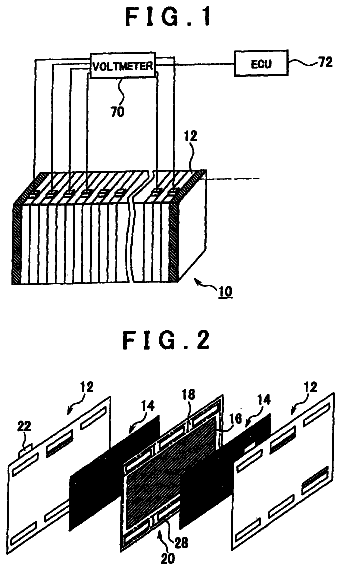
FIG. 1 is a perspective view schematically showing an exemplary configuration of a cell stack of a fuel cell according to Embodiment 1 of the present disclosure.
FIG. 2 is an exploded schematic view of the cell stack of the fuel cell of FIG. 1.
FIG. 3A is a cross-sectional view taken along line IIIA-IIIA of FIG. 1.
FIG. 3B is a schematic view showing a state where the cell stack of the fuel cell is assembled (fastened).
FIG. 4 is a table showing a result of simulation conducted to determine whether or not a local stress is generated in an end plate or the like, depending on the positions at which a first band engagement portion and a second band engagement portion are provided, in the cell stack of the fuel cell.
FIG. 5 is a perspective view schematically showing an exemplary configuration of a cell stack of a fuel cell according to Embodiment 2 of the present disclosure.
FIG. 6 is an exploded schematic view of the cell stack of the fuel cell of FIG. 5.
FIG. 7 is a perspective view schematically showing an exemplary configuration of a cell stack of a fuel cell according to Embodiment 3 of the present disclosure.
FIG. 8 is a perspective view schematically showing an exemplary configuration of a first band member and a second band member of the cell stack of the fuel cell of FIG. 7.
FIG. 9 is a perspective view schematically showing an exemplary configuration of a cell stack of a fuel cell according to Embodiment 4 of the present disclosure.
FIG. 10 is a perspective view schematically showing an exemplary configuration of a cell stack of a fuel cell according to Embodiment 5 of the present disclosure.
FIG. 11 is a perspective view schematically showing an exemplary configuration of a fastener band of the cell stack of the fuel cell of FIG. 10.
FIG. 12 is a perspective view schematically showing an exemplary configuration of a cell stack of a fuel cell according to Embodiment 6 of the present disclosure.
FIG. 13 is a perspective view schematically showing an exemplary configuration of a cell stack of a fuel cell according to Embodiment 7 of the present disclosure.
Detailed description of the preferred embodiments
Hereinafter, preferred embodiments of the present disclosure will be described with reference to the drawings. Throughout the drawings, the same or corresponding components and members are designated by the same reference numerals and repetitive description thereof will be omitted. In the embodiments described below, the present disclosure is applied to a polymer electrolyte fuel cell (PEFC) but is widely applicable to other kinds of fuel cells such as, but not limited to, solid oxide fuel cell (SOFC) or phosphoric acid fuel cell (PAFC).
Embodiment 1
Configuration of a Cell Stack of a Fuel Cell
FIG. 1 is a perspective view schematically showing a configuration of a cell stack of a fuel cell according to Embodiment 1 of the present disclosure. FIG. 2 is an exploded schematic view of the cell stack of the fuel cell of FIG. 1. In FIGS. 1 and 2, the upper and lower sides of the cell stack of the fuel cell are expressed as the upper and lower sides in these Figures.
As shown in FIGS. 1 and 2, a cell stack 100 of a fuel cell includes a cell stack body 50 having a rectangular parallelepiped configuration, a fastener band 80 including a first U-shaped band member 60 and a second U-shaped band member 70, and a pair of engagement pins 90. The first band member 60 and the second band member 70 extend so as to surround the cell stack body 50 and so as to cover the upper surface (upper end surface) of the cell stack body 50, the lower surface (lower end surface) of the cell stack body 50, and a pair of opposing side surfaces of the cell stack body 50. The first band member 60 has plural (in this embodiment, three) through-holes 69 on a top surface thereof covering the upper surface of the cell stack body 50. The second band member 70 has plural (in this embodiment, three) through-holes 79 on a bottom surface thereof covering the lower surface of the cell stack body 50. Pipes 201 used for supplying to or discharging from the cell stack 100 (cell stack body 50) of the fuel cell, a fluid such as a fuel gas flowing in the cell stack body 50, are respectively inserted into the through-holes 69 and 79.
A first tubular band member engagement portion 61 and a second tubular band member engagement portion 62 are provided at both ends of the first band member 60, respectively. Likewise, a third tubular band member engagement portion 71 and a fourth tubular band member engagement portion 72 are provided at both ends of the second band member 70, respectively.
One of the pair of the engagement pins 90 is inserted into the first band member engagement portion 61 of the first band member 60 and the fourth band member engagement portion 72 of the second band member 70. In the same manner, the other engagement pin 90 is inserted into the second band member engagement portion 62 of the first band member 60 and the third band member engagement portion 71 of the second band member 70. Thereby, the first band member engagement portion 61 of the first band member 60 and the fourth band member engagement portion 72 of the second band member 70 are engageable with each other via the engagement pin 90, while the second band member engagement portion 62 of the first band member 60 and the third band member engagement portion 71 of the second band member 70 are engageable with each other via the engagement pin 90. In other words, the first band member engagement portion 61 of the first band member 60 and the fourth band member engagement portion 72 of the second band member 70 are indirectly engageable with each other via the engagement pin 90, while the second band member engagement portion 62 of the first band member 60 and the third band member engagement portion 71 of the second band member 70 are indirectly engageable with each other via the engagement pin 90. Thus, when the engagement pins 90 are inserted, the first band member 60 and the second band member 70 are secured together.
The first band member 60 and the second band member 70 are made of a material which is excellent in tensile strength and anticorrosion, such as, but not limited to, resin (engineering plastic, elastomer, etc), stainless steel (e.g., SUS304), or chrome molybdenum steel. The engagement pins 90 are made of a material such as, but not limited to, chrome molybdenum steel, or stainless steel (e.g., SUS304).
With reference to FIGS. 3A and 3B, the structures of the first band member engagement portion 61 and the second band member engagement portion 62 of the first band member 60 and the third band member engagement portion 71 and the fourth band member engagement portion 72 of the second band member 70 will be described in greater detail. Since the first band member engagement portion 61 and the second band member engagement portion 62 of the first band member 60 have the same structure, and the third band member engagement portion 71 and the fourth band member engagement portion 72 of the second band member 70 have the same structure, the first band member engagement portion 61 of the first band member 60 and the fourth band member engagement portion 72 of the second band member 70 will be described hereinafter.
FIG. 3A is a cross-sectional view taken along line IIIA-IIIA of FIG. 1. FIG. 3B is a schematic view showing a state where the cell stack 100 of the fuel cell is assembled (fastened). In FIGS. 3A and 3B, to clearly distinguish between the first band member engagement portion 61 of the first and member 60 and the fourth band member engagement portion 72 of the second band member 70, the first band member engagement portion 61 is hatched.
As shown in FIGS. 1 to 3B, an engagement portion forming section 63 and an engagement portion forming section 73 are provided at the end of the first band member 60 and at the end of the second band member 70, respectively so as to protrude along the surfaces (in a vertical direction) of the first and second band members 60 and 70. The engagement portion forming sections 63 and 73 form the first band member engagement portion 61, the second band member engagement portion 62, the third band member engagement portion 71 and the fourth band member engagement portion 72. The engagement portion forming sections 63 and 73 are each folded back to form a tubular shape. The tip end portion of the engagement portion forming section 63 and the base end portion of the engagement portion forming section 63 are welded and fastened to each other by screws 64, while the tip end portion of the engagement portion forming section 73 and the base end portion of the engagement portion forming section 73 are welded and fastened to each other by screws 74.
To be specific, the first band member engagement portion 61 protrudes from one end of the first band member 60 in one direction (in this embodiment, downward) in a direction in which cells 10 are stacked, and the second band member engagement portion 62 protrudes downward from the other end of the first band member 60. In the same manner, the third band member engagement portion 71 protrudes from one end of the second band member 70 in the other direction (in this embodiment, upward) in the direction in which cells 10 are stacked, and the fourth band member engagement portion 72 protrudes upward from the other end of the second band member 70. In other words, the third band member engagement portion 71 is disposed such that the third band member engagement portion 71 and the second band member engagement portion 62 are aligned when viewed from a direction which is perpendicular to the direction in which the cells 10 are stacked and extend parallel to a pair of side surfaces of the cell stack structure 20. Likewise, the fourth band member engagement portion 72 is disposed such that the fourth band member engagement portion 72 and the first band member engagement portion 61 are aligned when viewed from the direction which is perpendicular to the direction in which the cells 10 are stacked and extend parallel to the pair of side surfaces of the cell stack structure 20. As used herein, the phrase "the direction which is perpendicular to the direction in which the cells 10 are stacked and extend parallel to the pair of side surfaces of the cell stack structure 20" means a direction in which a long side of the side surface of the cells 10 which is covered with the first band member 60 or the second band member 70 extends (hereinafter referred to as the direction in which the long side of the side surface of the cells 10 extends).
The first band member engagement portion 61 and the second band member engagement portion 62 having the above structure are provided with insertion holes (tubular inner spaces) 65, respectively extending in the direction perpendicular to the direction (in this embodiment, vertical direction) in which the cells 10 are stacked. In the same manner, the third band member engagement portion 71 and the fourth band member engagement portion 72 are provided with insertion holes (tubular inner spaces) 75, respectively extending in the direction perpendicular to the direction (in this embodiment, vertical direction) in which the cells 10 are stacked.
To be specific, the insertion holes 65 and the insertion holes 75 extend along the side surface of the cells 10 (to be precise, the long side of the side surface of the cells 10). The insertion hole 65 of the first band member engagement portion 61 and the insertion hole 75 of the fourth band member engagement portion 72 are arranged in the direction perpendicular to the direction in which the cells 10 are stacked. In the same manner, the insertion hole 65 of the second band member engagement portion 62 and the insertion hole 75 of the third band member engagement portion 71 are arranged in the direction perpendicular to the direction in which the cells 10 are stacked. To be more specific, the insertion hole 65 of the first band member engagement portion 61 and the insertion hole 75 of the fourth band member engagement portion 72 are arranged in the direction which is perpendicular to the direction in which the cells 10 are stacked and is parallel to the pair of side surfaces of the cell stack structure 20. In the same manner, the insertion hole 65 of the second band member engagement portion 62 and the insertion hole 75 of the third band member engagement portion 71 are arranged in the direction which is perpendicular to the direction in which the cells 10 are stacked and is parallel to the pair of side surfaces of the cell stack structure 20.
In other words, the insertion hole 65 of the first band member engagement portion 61 and the insertion hole 75 of the fourth band member engagement portion 72 are arranged so as to overlap or align with each other when viewed from the direction of the long side of the side surface of the cells 10. The insertion hole 65 of the second band member engagement portion 62 and the insertion hole 75 of the third band member engagement portion 71 are arranged so as to overlap or align with each other when viewed from the direction of the long side of the side surface of the cells 10. As used herein, the phrase "the insertion hole 65 and the insertion hole 75 are arranged in the direction perpendicular to the direction in which the cells 10 are stacked or arranged in the direction which is perpendicular to the direction in which the cells 10 are stacked and is parallel to the pair of side surfaces of the cell stack structure 20" is meant to include that a part of the insertion hole 65 overlaps a part of the insertion hole 75 when viewed from the direction in which the long side of the side surface of the cells 10 covered with the first band member 60 or the second band member 70 extends, as well as that the insertion hole 65 and the insertion hole 75 are arranged so as to overlap or align with each other, when viewed from the direction in which the long side of the side surface of the cells 10 covered with the first band member 60 or the second band member 70 extends.
The first band member engagement portion 61 and the third band member engagement portion 71 form a first band engagement portion, while the second band member engagement portion 62 and the fourth band member engagement portion 72 form a second band engagement portion. The insertion hole 65 of the first band member engagement portion 61 and the insertion hole 75 of the third band member engagement portion 71 form a first insertion hole, while the insertion hole 65 of the second band member engagement portion 62 and the insertion hole 75 of the fourth band member engagement portion 72 form a second insertion hole.
In Embodiment 1, the first band member engagement portion 61 of the first band member 60 is formed so as to overlap the second band member engagement portion 62 of the first band member 60, when viewed from the direction which is perpendicular to the direction in which the cells 10 are stacked. In the same manner, the third band member engagement portion 71 of the second band member 70 is formed so as to overlap the fourth band member engagement portion 72 of the second band member 70, when viewed from the direction which is perpendicular to the direction in which the cells 10 are stacked. In other words, the first band member engagement portion 61 of the first band member 60 and the second band member engagement portion 62 of the first band member 60 are formed symmetrically with respect to the cell stack body 50 sandwiched therebetween. In the same manner, the third band member engagement portion 71 of the second band member 70 and the fourth band member engagement portion 72 of the second band member 70 are formed symmetrically with respect to the cell stack body 50 sandwiched therebetween. In this embodiment, the first member engagement portion 61 of the first band member 60 and the fourth band member engagement portion 72 of the second member 70 are arranged at substantially the center of the side surface of the cell stack structure 20, and the second member engagement portion 62 of the first band member 60 and the third band member engagement portion 71 of the second band member 70 are arranged at substantially the center of the side surface of the cell stack structure 20.
The first band member engagement portion 61 of the first band member 60 and the fourth band member engagement portion 72 of the second band member 60 are formed not to overlap, when viewed from the direction in which the cells 10 are stacked, and the second band member engagement portion 62 of the first band member 60 and the third band member engagement portion 71 of the second band member 70 are formed not to overlap, when viewed from the direction in which the cells 10 are stacked.
The width of the first band member 60 and the width of the second band member 70 are desirably larger than the width for covering power generation sections (cathode and anode electrode sections) of the cells 10. This makes it possible to evenly press the power generation sections of the cells 10. In addition, the width of the first band member 60 and the width of the second band member 70 are desirably equal to or larger than the width of the end plates 34 as described later. This makes it possible to cover the entire end surfaces of the end plates 34 and evenly press the same. Thereby, stiffness of the end plate 34 need not be high and the material may be selected flexibly.
As shown in FIG. 3B, the first band member engagement portion 61 of the first band member 60 and the fourth band member engagement portion 72 of the second band member 70 are formed such that a length b in a long axis direction (direction in which the cells 10 are stacked) is not less than twice as large as a length a in a short axis direction (thickness direction of the first band member 60 and the second band member 70), when viewed from the thickness direction of the first band member 60 and the second band member 70. In this structure, the engagement pin 90 can be easily inserted into the first band member engagement portion 61 of the first band member 60 and the fourth band member engagement portion 72 of the second band member 70.
The engagement pin 90 is inserted into the first band member engagement portion 61 of the first band member 60 and the fourth band member engagement portion 72 of the second band member 70 such that the inner surface of the first band member engagement portion 61 and the inner surface of the fourth band member engagement portion 72 are engaged with the peripheral surface of the engagement pin 90. To be specific, the half of the peripheral surface of the engagement pin 90 is configured to contact each of the inner surface of the first band member engagement portion 61 and the inner surface of the fourth band member engagement portion 71.
In this state, the engagement pin 90, the first band member engagement portion 61 and the fourth band member engagement portion 72 are applied with a force from all directions and thereby fixed, increasing a force against a vibration or an impact applied from outside. Unlike the conventional method in which the cell stack body 50 is fastened using the bolts and the nuts, a large protruding portion is unnecessary. This reduces a space in which the cell stack 100 of the fuel cell is installed or the surface area of the cell stack 100. By reducing the surface area of the cell stack 100 of the fuel cell, the heat radiation amount of the cell stack 100 can be reduced. Thus, the cell stack 100 can be used as an electric power supply of a cogeneration system which has a high heat recovery property.
In the cell stack 100 of the conventional fuel cell, a contact resistance between adjacent cells 10 and a contact resistance between the separator and the MEA forming the cell 10 increase due to a large or small fastening load, an uneven fastening load, etc, which may sometimes result in degraded cell performance. In the structure for fastening the band engagement portion with the nuts and the bolts, in the polymer electrolyte fuel cell disclosed in Patent document 2, for example, there is a distance between a surface (band) generating a tension and a fulcrum point (engagement portion). For this reason, there is a chance that the engagement portion is deformed due to the tension of the band. The extent of such deformation depends greatly on a variation in stiffness of the engagement portion, a variation in the tension of the band, etc. As a result, the polymer electrolyte fuel cell disclosed in Patent document 2 is incapable of obtaining a stable fastening load.
In contrast, in the cell stack 100 of the fuel cell of Embodiment 1, as shown in FIG. 3A, the fulcrum point (engagement pin 90) is positioned on the surface generating a tension (surface including the center lines 101A and 101B and being perpendicular to the stacking direction) so that the deformation of the engagement portion forming sections 63 and 73 is suppressed. Since the surface generating a tension and the fulcrum point are located on substantially the same plane, the cell stack 100 of the fuel cell can substantially suppress variations in the fastening load due to the deformation.
Although the tip end portion and the base end portion of the engagement portion forming section 63 are welded and fastened to each other using the screws 64 and the tip end portion and the base end portion of the engagement portion forming section 73 are welded and fastened to each other using the screws 74, they may alternatively be joined to each other only by welding, only by the screws or by the bonding agent, so long as the engagement portion forming section 63 and the engagement portion forming section 73 are able to have a stiffness sufficient to withstand a fastening pressure. Although the engagement pin 90 has a circular cross-section, its shape is not so limited provided that its peripheral surface has a circular-arc portion. For example, the engagement pin 90 may have a cross-section of an oval shape or an elongate-circle shape.
Next, the components of the cell stack 100 of the fuel cell of Embodiment 1 will be described with reference to FIG. 2.
The cell stack body 50 includes a cell stack structure 20 including plural plate-shaped cells (unit cells) 10 which are stacked, a pair of current collectors 31, a pair of insulating plates 32, an elastic member 33, and a pair of end plates 34 sandwiching these members therebetween. The cell stack body 50 has a fuel gas supply manifold 51, a fuel gas exhaust manifold (not shown), an oxidizing gas supply manifold 52, an oxidizing gas exhaust manifold (not shown), a cooling medium supply manifold 53, and a cooling medium discharge manifold (not shown), which are formed to penetrate through the cell stack body 50. Each manifold is provided with a connecting member 202 for connecting the pipe 201 to the cell stack body 50 (cell stack 100 of the fuel cell).
Each cell 10 includes a MEA (membrane-electrode-assembly) consisting of a polymer electrolyte membrane, an anode and cathode disposed on both surfaces thereof, gaskets, and a pair of separators. By contact between the separators of adjacent cells 10, all of the cells 10 are electrically connected in series. By stacking the cells 10 having the above structure in a thickness direction thereof, the cell stack structure 20 is formed.
The pair of current collectors 31 are disposed at the both ends of the cell stack structure 20 in the direction in which the cells 10 are stacked. Terminal members 31a are provided on the side surfaces of the current collectors 31. Electric wires (not shown) are connected to the terminal members 31a. Thus, an electric power generated in the respective cells 10 can be output to outside through the terminal members 31a. It is sufficient that the current collectors 31 are made of a material which is gas-impermeable and electrically conductive. The current collectors 31 may be made of dense carbon or metal such as, for example, copper.
The pair of insulating plates 32 are disposed outside the current collectors 31 of the cell stack structure 20 such that they are respectively in contact with the main surfaces of the current collectors 31. In other words, the pair of insulating plates 32 sandwich and retain a stack of the cell stack structure 20 and the current collectors 31. The insulating plates 32 may be made of an insulating material such as rubber or plastic.
The plate-shaped elastic member 33 is disposed under the insulating plate 32 located at the lower side of the pair of insulating plates 32. The elastic member 33 serves to apply a pressing force in the stacking direction to the stack including the cell stack structure 20, the current collectors 31, and others. By the elastic force of the elastic member 33, a fastening pressure is applied to the fastener band 80. In this embodiment, as the elastic member 33, a sheet made of rubber such as fluorine-containing rubber or EPDM may be utilized.
The pair of end plates 34 are disposed at the both ends of the stack including the cell stack structure 20, the current collectors 31, and others such that they are in contact with the main surface of the insulating plate 32 or the main surface of the elastic member 33. The end plates 34 serve to apply the fastening force of the fastener band 80 to the cell stack structure 20, the current collectors 31, and others with an even surface pressure. The end plates 34 are formed using a stiff material such as, hard plastic or steel, to prevent deformation due to the fastening structure. As shown in FIGS. 1 and 2, the size of the main surfaces of the end plates 34 is preferably set slightly larger than the size of the cells 10, the main surfaces of the current collectors 31, and others. The pair of sides of the main surfaces of the end plates 34, which are in contact with the fastener band 80, are preferably chamfered so that the chamfered portions have a smaller thickness than the center portions.
Thus, the fastener band 80 extends between the pair of end plates 34 to be apart from the side surfaces (i.e., not in contact) of the cell stack structure 20 and the current collectors 31. This makes it possible to prevent a short circuit between the cell stack structure 20 and the current collectors 31 which would otherwise occur because of the fastener band 80. In addition, this makes it possible to prevent the fastening pressure from the fastener band 80 being applied unevenly with respect to the main surfaces of the end plates 3. As a result, the anode and the cathode forming the MEA of each cell 10 can contact the polymer electrolyte membrane of the MEA with an even surface pressure.
Next, a fastening method of the cell stack 100 of the fuel cell of Embodiment 1 will be described with reference to FIGS. 1 to 3.
[Fastening Method of Cell Stack of Fuel Cell]
The description continues in the full USPTO document.
 Lapsed, fee not paid6 drawings