 Lapsed, fee not paid13 drawings
Vehicles & Drones · US 8,695,541 B2
Cooling system for internal combustion engine
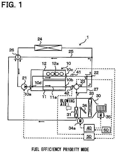
During engine warm-up, a flow regulating unit in a cooling system operates in a fuel efficiency priority mode.
US 8,695,545 B2 · Assignee: Toyota Jidosha Kabushiki Kaisha · Inventors: Tateno; Manabu
Sheet 1 of 15 from the published document. All sheets in the USPTO PDF
A phase changing device 100A of a camshaft is provided to a dual structure camshaft 10 which is rotated by a driving force input thereto and which includes an inner shaft 11 and an outer shaft 12. The phase changing device 100A of the camshaft includes a phase changing portion 1A including a single housing 2 defining: an advance hydraulic chamber R1 advancing wholly a phase of the camshaft 10 by a hydraulic pressure; a retard hydraulic chamber R2 retarding wholly the phase of the camshaft 10 by a hydraulic pressure; and a phase difference hydraulic chamber R3 changing a difference between a phase of the inner shaft 11 and a phase of the outer shaft 12 by a hydraulic pressure.
For example, a dual structure camshaft is used for an engine. Patent Document 1 discloses a valve timing device including: a camshaft composed of an inner camshaft and an outer camshaft; and a first phase control mechanism and a second phase control mechanism respectively provided at both ends of the camshaft. Patent Document 2 discloses a camshaft including an inner shaft and an outer shaft that are provided at one end thereof with a hydraulic device.
1 of 15 drawing sheets so far from the published document, cropped to the drawing. Every sheet is in the USPTO PDF.
What the patent claimed, word for word. All of it is now free to use.
This application is a National Stage of International Application No. PCT/JP2011/058311, filed on Mar. 31, 2011, the contents of all of which are incorporated herein by reference in their entirety.
The present invention relates to a phase changing device of a camshaft, and more particularly, to the phase changing device provided to a dual structure camshaft including an inner shaft and an outer shaft.
For example, a dual structure camshaft is used for an engine. Patent Document 1 discloses a valve timing device including: a camshaft composed of an inner camshaft and an outer camshaft; and a first phase control mechanism and a second phase control mechanism respectively provided at both ends of the camshaft. Patent Document 2 discloses a camshaft including an inner shaft and an outer shaft that are provided at one end thereof with a hydraulic device.
Patent Document
[Patent Document 1] Japanese Patent Application Publication No. 2009-144521 [Patent Document 2] Japanese National Publication of International Patent Application Publication No. 2008-528871
Problems to be Solved by the Invention
The camshaft having the dual structure rotates in response to the input driving force. In contrast, in order to control the phase of the dual structure camshaft, the phase of the camshaft is wholly advanced or retarded, and in addition the phase difference between the inner shaft and the outer shaft is changed. In order to control the phase in such a way, the first and second phase control mechanisms may be provided as an example of the valve timing device disclosed in Patent Document 1.
However, two phase control mechanisms each have a hydraulic chamber for advance and a hydraulic chamber for retard, that is, there are four hydraulic chambers. Thus, there may be a disadvantage of downsizing. Additionally, since two phase control mechanisms are independently provided in the axial direction, the full length in the axial direction tends to be longer. Thus, there may be a disadvantage of downsizing. Further, since two phase control mechanisms are independently provided in the axial direction, there is a cost disadvantage.
Moreover, two phase control mechanisms have to be controlled in this case. Therefore, it may be complicated to control the phase of the camshaft. In addition, torque reaction forces are applied to each of the phase control mechanisms from the inner shaft and the outer shaft. For this reason, the torque reaction forces are canceled or increased depending on the phase difference between the inner and outer shafts. This influences the torque variation of the whole camshaft. Thus, it may be difficult to desirably control the phase of the camshaft as desired.
The present invention has been made in view of the above circumstances and has an object to provide a phase changing device of a camshaft which controls a phase of a dual structure camshaft with an advantage of downsizing and saving cost, and which suitably control the phase of the camshaft.
Means for Solving the Problems
The present invention is a phase changing device of a camshaft provided to a dual structure camshaft which is rotated by a driving force input thereto and which includes an inner shaft and an outer shaft, the camshaft phase changing device including a phase changing portion comprising a single housing defining: an advance hydraulic chamber advancing wholly a phase of the camshaft by a hydraulic pressure; a retard hydraulic chamber retarding wholly the phase of the camshaft by a hydraulic pressure; and a phase difference hydraulic chamber changing a difference between a phase of the inner shaft and a phase of the outer shaft by a hydraulic pressure.
In the present invention, the advance hydraulic chamber, the retard hydraulic chamber, and the phase difference hydraulic chamber may be arranged in a circumferential direction of the camshaft, and may define a pair of the hydraulic chambers acting on one another.
In the present invention, the phase changing portion may include: a housing as the housing into which a driving force for driving the camshaft is input; a first rotor driving the inner shaft; and a second rotor driving the outer shaft, and the housing may be sandwiched between the first and second rotors.
In the present invention, the first and second rotors may respectively include rotor bodies, and each of the rotor bodies may be provided at an outer circumferential portion with a sliding portion slidable with respect to the housing.
In the present invention, the housing may include a driving force input portion into which the driving force is input and which overlaps the second rotor in an axial direction.
In the present invention, the inner shaft may include a flange portion sandwiched between the second rotor and the outer shaft in an axial direction with the phase changing portion provided to the camshaft.
In the present invention, the outer shaft selected from the inner and outer shafts may be provided within the outer shaft with hydraulic path portions which respectively communicate with the advance hydraulic chamber, the retard hydraulic chamber, and the phase difference hydraulic chamber.
In the present invention, the phase changing portion may further include a restraining portion which releasably restrains a relative movement between the first and second rotors.
The present invention may further include: a first hydraulic control valve connected to the advance hydraulic chamber and the retard hydraulic chamber, and controlling a hydraulic pressure to be supplied; and a second hydraulic control valve connected to the first hydraulic pressure control valve and the phase difference hydraulic chamber, and controlling a hydraulic pressure to be supplied.
In the present invention may further include: a first three-way valve connected to the advance hydraulic chamber and the retard hydraulic chamber, and switching a supply destination of the hydraulic pressure; a second three-way valve connected to the retard hydraulic chamber and the phase difference hydraulic chamber, and switching a supply destination of the hydraulic pressure; and a hydraulic pressure control valve connected to the first and second three-way valves, and controlling a hydraulic pressure to be supplied.
Effects of the Invention
The present invention can control a phase of a dual structure camshaft with an advantage of downsizing and saving cost, and suitably control the phase of the camshaft.
FIG. 1 is a general configuration view of a first embodiment;
FIG. 2 is a view of a camshaft installed in an engine;
FIG. 3 is an exploded view of a phase changing portion of the first embodiment;
FIG. 4 is a first sectional view of the phase changing portion of the first embodiment;
FIG. 5 is a second sectional view of the phase changing portion of the first embodiment;
FIG. 6 is a view of a hydraulic circuit configuration of the first embodiment;
FIGS. 7A to 7D are views of an example of a phase control of the first embodiment;
FIG. 8 is a view of a general configuration of a second embodiment;
FIG. 9 is a first sectional view of the phase changing portion of the second embodiment;
FIG. 10 is a second sectional view of the phase changing portion of the second embodiment;
FIG. 11 is a general configuration of a third embodiment;
FIG. 12 is a view of a hydraulic circuit configuration of the third embodiment;
FIG. 13 is a general configuration view of a phase changing device of a fourth embodiment;
FIGS. 14A to 14C are views of a hydraulic circuit configuration of the fourth embodiment; and
FIGS. 15A to 15E are views of an example of a phase control of the fourth embodiment.
Embodiments according to the present invention will be described with reference to drawings.
[First Embodiment]
FIG. 1 is a general configuration view of a phase changing device (hereinafter referred to as phase changing device) 100A according to the present embodiment. FIG. 2 is a view of a camshaft 10 installed in an engine 50. FIG. 2 illustrates the engine 50 having the camshaft 10 provided to the same type of two engine valves (herein, intake valves) 51 and 52 for each cylinder. For example, the same type of valves may be exhaust valves.
As illustrated in FIG. 1, the general configuration of the phase changing device 100A includes a phase changing portion 1A, and a hydraulic (corresponding to liquid pressure) circuit portion 30A, and an ECU 70A. The phase changing portion 1A, the hydraulic circuit portion 30A, and the ECU 70A will be described sequentially. The phase changing device 100A is provided in the camshaft 10. In the general configuration of the phase changing device 100A, the camshaft 10 is provided with a flange portion 11c, hydraulic path portions L1, L2, and L3 as will be described later.
The camshaft 10 has a dual structure provided with an inner shaft 11 and an outer shaft 12. The inner shaft 11 has a core. The outer shaft 12 has a hollow. The inner shaft 11 is inserted into the outer shaft 12 from its one end. The inner shaft 11 and the outer shaft 12 are concentrically arranged and rotatable relative to each other. The camshaft 10 rotates in response to the input driving force.
As illustrated in FIG. 2, the camshaft 10 is capable of changing the phases of the engine valves 51 and 52 by the inner shaft 11 and the outer shaft 12. In this regard, the inner shaft 11 of the camshaft 10 is provided with a first cam C1 for driving the first engine valve 51, and the outer shaft 12 is provided with a second cam C2 for driving the second engine valve 52.
FIG. 3 is an exploded view of the phase changing portion 1A. FIG. 4 is a first sectional view of the phase changing portion 1A. FIG. 5 is a second sectional view of the phase changing portion 1A. FIGS. 3 and 4 illustrate the phase changing portion 1A in addition to the camshaft 10. FIG. 4 illustrates a cross section including a central axis of the phase changing portion 1A. FIG. 5 illustrates a cross section perpendicular to the central axis of the phase changing portion 1A.
The phase changing portion 1A includes a housing 2, a first rotor 3, and a second rotor 4. The housing 2 has a general cylindrical shape, and includes inner spaces such as an advance hydraulic chamber R1, a retard hydraulic chamber R2, and a phase difference hydraulic chamber R3 as will be described later. The housing 2 includes: a driving force input portion 2a; a first sliding portion 2b; and a second sliding portion 2c, and housing vane portions 2d.
The driving force input portion 2a is provided at the outer circumferential portion of the housing 2. The driving force for driving the camshaft 10 is input to the housing 2 the through driving force input portion 2a. Specifically, the driving force input portion 2a is a chain sprocket. A part of the output of the engine 50 is changed into the driving force, and then the driving force is input to the driving force input portion 2a through a chain. The housing 2 is provided with the driving force input portion 2a at a position overlapping the second rotor 4 in the axial direction.
The first sliding portion 2b is provided at the inside of one end of the housing 2. The second sliding portion 2c is provided at the inside of the other end of the housing 2. The housing vane portions 2d are provided in the housing 2 at the inside of a middle portion between the sliding portions 2b and 2c. An inner cylindrical surface partially divided by the housing vane portion 2d is provided at a portion other than the housing vane portions 2d of the middle portion. The inner diameter of this portion is an inner diameter of the housing 2.
Specifically, the sliding portions 2b and 2c each have an inner diameter larger than the inner diameter of the housing 2, and are concentrically provided at the whole inner circumference of the housing 2. The first sliding portion 2b has a given depth from one end of the housing 2 in the axial direction, and the second sliding portion 2c has a given depth from the other end thereof
The housing vane portions 2d each have a cross section perpendicular to the axial direction, and the cross section is narrower in the radially inward direction such that the housing vane portions 2d have the same fan shapes. In this regard, the radial inner side of the housing vane portion 2d is provided with an inner circumferential surface concentric with the inner cylindrical surface of the middle portion of the housing 2. The width of the housing vane portion 2d in the axial direction depends on the depths of the sliding portions 2b and 2c. The plural (herein, two) housing vane portion 2d are provided.
The first rotor 3 includes: a rotor body 3a, a cylindrical portion 3b, and a first vane portion 3c. The rotor body 3a has a disc shape. The rotor body 3a is provided at its center with a center bolt insertion hole 3aa which concentrically extends in the axial direction. The first rotor 3 is provided at its outer circumferential portion of the rotor body 3a with a sliding portion 3ab slidable with respect to the housing 2. The outer diameter of the rotor body 3a is set to be substantially the same as the inner diameter of the first sliding portion 2b. The width of the rotor body 3a in the axial direction is set to be substantially the same as the depth of the first sliding portion 2b.
The cylindrical portion 3b axially extends from an end, assembled into the housing 2, of both ends of the rotor body 3a. The cylindrical portion 3b is concentric with the rotor body 3a. The outer diameter of the cylindrical portion 3b is set to be substantially the same as the inner diameter of the inner circumferential surface of the housing vane portion 2d. The width of the cylindrical portion 3b in the axial direction is set to be substantially the same as the width of the housing vane portion 2d in the axial direction.
The first vane portions 3c are provided at the rotor body 3a and the cylindrical portion 3b. The first vane portions 3c axially extend from the end, assembled into the housing 2, of both ends of the rotor body 3a. Further, the first vane portions 3c each have a cross section perpendicular to the axis, and the cross section is wider in the radially outward direction such that the first vane portions 3c have the same fan shapes.
The first vane portion 3c has an outer circumferential surface which is located at the radial outer side thereof and which is concentric with the rotor body 3a. The outer diameter of this outer circumferential surface is set to be substantially the same as the inner diameter of the inner cylindrical surface of the middle portion of the housing 2. The width of the first vane portion 3c in the axial direction is substantially the same as the width of the cylindrical portion 3b in the axial direction. The plural (herein, two) first vane portions 3c are provided.
The second rotor 4 includes a rotor body 4a and second vane portion 4b. The rotor body 4a has a disc shape. The rotor body 4a is provided at its center with a camshaft insertion hole 4aa which concentrically extends in the axial direction. The camshaft insertion hole 4aa has a smaller diameter at one end opposite to the other end into which the camshaft 10 is inserted in the axial direction. The inner diameter of the smaller diameter portion of the camshaft insertion hole 4aa is larger than the inner diameter of the cylindrical portion 3b and is smaller than the outer diameter of the cylindrical portion 3b. An end surface of the smaller diameter portion of the camshaft insertion hole 4aa, selected from both end surfaces of the rotor body 4a, is assembled into the housing 2.
The second rotor 4 is provided at its outer circumferential portion of the rotor body 4a with a sliding portion 4ab slidable with respect to the housing 2. The outer diameter of the rotor body 4a is set to be substantially the same as the inner diameter of the second sliding portion 2c. The width of the rotor body 4a in the axial direction is set to be substantially the same as or larger than the depth of the second sliding portion 2c.
The second vane portion 4b axially extends from an end, assembled into the housing 2, of both ends of the rotor body 4a. Further, the second vane portions 4b each have a cross section perpendicular to the axis, and the cross section is gradually wider from the radial inner side to the radial outer side such that second vane portions 4c have the same fan shapes. The second vane portion 4b has an inner circumferential surface which is located at the radial inner side thereof and which is concentric with the rotor body 4a. The second vane portion 4b has an outer circumferential surface which is located at the radial outer side thereof and which is concentric with the rotor body 4a.
The inner diameter of the second vane portion 4b is set to be substantially the same as the outer diameter of the cylindrical portion 3b. The outer diameter of the second vane portion 4b is set to be substantially the same as the inner diameter of the inner cylindrical surface of the middle portion of the housing 2. The width of the second vane portion 4b in the axial direction is set to be substantially the same as the width of the housing vane portion 2d in the axial direction. The plural (herein, two) second vane portions 4b are provided.
The phase changing portion 1A has the single housing 2 including: advance hydraulic chambers R1 advancing wholly a phase of the camshaft 10 by oil hydraulic pressure; retard hydraulic chambers R2 retarding the phase of the camshaft 10 by oil hydraulic pressure; and phase difference hydraulic chambers R3 changing a difference in phase between the inner shaft and the outer shaft by oil hydraulic pressure. In the phase changing portion 1A, the housing 2 is sandwiched between the rotors 3 and 4.
In this regard, specifically, the first rotor 3 is provided to the housing 2 such that the rotor body 3a is accommodated by the first sliding portion 2b and the first vane portions 3c are accommodated by the middle portion. Also, the second rotor 4 is provided to the housing 2 such that the rotor body 4a is accommodated by the second sliding portion 2c and the second vane portions 4b are accommodated by the middle portion. Thus, the vane portions 2d, 3c, and 4b are arranged in the circumferential direction.
The vane portions 2d, 3c, and 4b arranged in the circumferential direction are pairs of the vane portions 2d, 3c, and 4b. In this regard, the phase changing portion 1A includes plural pairs (herein, two pairs) of the vane portions 2d, 3c, and 4b. Specifically, as for one pair of the vane portions 2d, 3c, and 4d, the housing vane portion 2d, the first vane portion 3c, and the second vane portion 4b are arranged in this order in the phase advance direction F.
The advance hydraulic chamber R1 is formed between the housing vane portion 2d and the first vane portion 3c adjacent to each other in the circumferential direction. Also, the retard hydraulic chamber R2 is formed between the housing vane portion 2d and the second vane portion 4b adjacent to each other in the circumferential direction. Further, the phase difference hydraulic chamber R3 is formed between the vane portions 3c and 4b adjacent to each other in the circumferential direction. The hydraulic chambers R1, R2, and R3 influence one another. In this regard, the hydraulic chambers R1 and R3 influence each other through the first vane portion 3c. The hydraulic chambers R2 and R3 influence each other through the second vane portion 4b. Also, the hydraulic chambers R1 and R2 influence each other through the vane portions 3c and 4b.
Such hydraulic chambers R1, R2, and R3 are arranged in the circumferential direction so as to define pairs of the hydraulic chambers R1, R2, and R3 influencing one another. The phase changing portion 1A includes plural pairs (herein, two pairs) of the hydraulic chambers R1, R2, and R3. As for the hydraulic chambers R1 to R3, specifically, the advance hydraulic chamber R1, the phase difference hydraulic chamber R3, and the retard hydraulic chamber R2 are arranged in this order in the phase advance direction F.
Next, the camshaft 10 will be described in more detail. The inner shaft 11 includes a shaft portion 11a, a head portion 11b, and the flange portion 11c. The shaft portion 11a is a main body of the inner shaft 11, and is inserted into the outer shaft 12. The head portion 11b is provided at one end of the shaft portion 11a. The head portion 11b has a columnar shape, and is inserted into the cylindrical portion 3b through the camshaft insertion hole 4aa. The outer diameter of the head portion 11b is set to be substantially the same as the inner diameter of the cylindrical portion 3b. The width of the head portion 11b in the axial direction is set to be greater than that of the cylindrical portion 3b in the axial direction.
The flange portion 11c is provided around the whole end, near the shaft portion 11a, of the head portion 11b. The outer diameter of the flange portion 11c is set to be greater than the smaller diameter portion of the camshaft insertion hole 4aa and smaller than the portion other than the smaller diameter portion. The inner shaft 11 is formed with a center bolt hole opening at the center of the head portion 11b and concentric thereto.
The outer shaft 12 includes a shaft portion 12a, and an end portion 12b, a flange portion 12c, and a hollow portion 12d. The shaft portion 12a is a main body of the outer shaft 12. The end portion 12b is provided at one end of the outer shaft 12. The end portion 12b has a columnar shape, and is inserted into the camshaft insertion hole 4aa. The outer diameter of the end portion 12b is set to be substantially the same as the inner diameter of the portion other than the smaller diameter portion of the camshaft insertion hole 4aa. The width of the end portion 12b in the axial direction is set to be smaller than the width of the portion other than the smaller diameter portion of the camshaft insertion hole 4aa.
The flange portion 12c is provided around an end, near the shaft portion 12a, of the end portion 12b. The flange portion 12c is formed with bolt insertion holes extending in the axial direction. Plural bolt insertion holes are formed at even intervals in the circumferential direction. The hollow portion 12d extends in the axial direction and is concentric. The hollow portion 12d has an inner cylinder surface, and opens at the center of the end portion 12b. The inner diameter of the hollow portion 12d is set to be substantially the same as the outer diameter of the shaft portion 11a.
The first rotor 3 is integrated with the inner shaft 11 and the second rotor 4 is integrated with the outer shaft 12 with the housing 2 sandwiched between the rotors 3 and 4, thereby providing the phase changing portion 1A to the camshaft 10. Specifically, the first rotor 3 is secured to the inner shaft 11 by the center bolt 21 to be integrated with the inner shaft 11. Specifically, the second rotor 4 is secured to the outer shaft 12 by plural fastening bolts 22 to be integrated with the outer shaft 12. The center bolt 21 is tightened into the center bolt hole through the center bolt insertion hole 3aa. The fastening bolt 22 is tightened into a bolt hole formed in the rotor body 4a through the bolt insertion hole.
A first knock pin 23 corresponding to a first positioning member is provided in the first rotor 3 and the inner shaft 11. Specifically, the first knock pin 23 is provided at the rotor body 3a and the head portion 11b. The first knock pin 23 positions the first rotor 3 and the inner shaft 11 in the circumferential direction. The second knock pin 24 corresponding to a second positioning member is provided in the second rotor 4 and the outer shaft 12. Specifically, the second knock pin 24 is provided at the rotor body 4a and the flange portion 12c. The second knock pin 24 positions the second rotor 4 and the outer shaft 12 in the circumferential direction.
In the phase changing device 100A, the inner shaft 11 is provided with the flange portion 11c to be sandwiched between the second rotor 4 and the outer shaft 12 with the phase changing portion 1A provided to the camshaft 10. In this regard, specifically, the flange portion 11c is arranged between the end portion 12b and the smaller diameter portion of the camshaft insertion hole 4aa of the second rotor 4 in the axial direction with the phase changing portion 1A provided to the camshaft 10. The width of the flange portion 11c in the axial direction is substantially the same as the width between the end portion 12b and the smaller diameter portion of the camshaft insertion hole 4aa of the second rotor 4 with the second rotor 4 integrated with the outer shaft 12.
In the phase changing device 100A, the inside of the outer shaft 12, selected from the inner shaft 11 and the outer shaft 12, is further provided with hydraulic path portions L1, L2, and L3 respectively communicating with the hydraulic chambers R1, R2, and R3. In this regard, the hydraulic path portions L1, L2, and L3 are provided in the outer shaft 12 and the second rotor 4. For example, the hydraulic path portions L1, L2, and L3 are provided in the outer shaft 12 and the second rotor 4 to intersect a wall defining the camshaft insertion hole 4aa from the end portion 12b.
In the phase changing device 100A, the outer shaft 12 is further provided at its circumferential portion with groove portions D1, D2, and D3 respectively communicating with the hydraulic path portions L1, L2, and L3. In this regard, one ends of the hydraulic path portions L1, L2, and L3 respectively communicate with the groove portions D1, D2, and D3, and the other ends of the hydraulic path portions L1, L2, and L3 respectively communicate with the hydraulic chambers R1, R2, and R3. The groove portions D1, D2, and D3 enable the hydraulic communication between the hydraulic path portions L1, L2, and L3 provided within the outer shaft 12 and the outside thereof.
FIG. 6 is a view of a hydraulic circuit configuration of the phase changing device 100A. A hydraulic pressure P1 indicates a hydraulic pressure in the advance hydraulic chamber R1, a hydraulic pressure P2 indicates a hydraulic pressure in the retard hydraulic chamber R2, and a hydraulic pressure P3 indicates a hydraulic pressure in the phase difference hydraulic chamber R3. As illustrated in FIGS. 1 and 6, the hydraulic circuit portion 30A includes a pump 31, a first hydraulic control valve 32, and a second hydraulic control valve 33A. The pump 31 is connected to the hydraulic control valves 32 and 33A in a branch connection manner. The first hydraulic control valve 32 is connected to the hydraulic path portions L1 and L2. Therefore, the first hydraulic control valve 32 is connected to the hydraulic chambers R1 and R2 to supply the hydraulic pressure thereto. The second hydraulic control valve 33A is connected to the hydraulic path portion L3. Therefore, the second hydraulic control valve 33A is connected to the hydraulic chamber R3 to supply oil thereto.
The pump 31 supplies the hydraulic oil as the hydraulic fluid, and generates the hydraulic pressure. The hydraulic control valves 32 are 33A control the hydraulic pressures in the supply destinations. The first hydraulic control valve 32 controls the hydraulic pressures P1 and P2 in the hydraulic chambers R1 and R2. The second hydraulic control valve 33A controls the hydraulic pressure P3 in the phase difference hydraulic chamber R3.
Specifically, the first hydraulic control valve 32 can supply the hydraulic pressure to one of the hydraulic chambers R1 and R2. In this case, the hydraulic pressure can be released from the other of the hydraulic chambers R1 and R2. The first hydraulic control valve 32 can supply the hydraulic pressures to the hydraulic chambers R1 and R2. Also, the hydraulic pressures can be released from the hydraulic chambers R1 and R2, respectively. Specifically, the second hydraulic control valve 33A can supply the hydraulic pressure to the phase difference hydraulic chamber R3. Also, the hydraulic pressures can be released from the phase difference hydraulic chamber R3. The resistances of the hydraulic pressure supply paths against the hydraulic chambers R1, R2, and R3, are set to be substantially the same as one another.
The ECU 70A is an electronic controlling device, and controls the hydraulic control valves 32 and 33A to control the phase of the camshaft 10 (at least one of the phases of the inner shaft 11 and the outer shaft 12). Therefore, the engine valves 51 and 52 are controlled. The ECU 70A detects the phase of the inner shaft 11 based on the output of a phase detection sensor 71 provided in the inner shaft 11, and detects the phase of the outer shaft 11 based on the output of a phase detection sensor 72 provided in the outer shaft 12. For example, the ECU 70A can control the hydraulic control valves 32 and 33A based on the detected phases of the inner shaft 11 and the outer shaft 12 in order to position the phase of the camshaft 10.
Next, an example of the phase control of the phase changing device 100A will be described with reference to FIGS. 7A to 7D. FIGS. 7A to 7D are views of an example of the phase control of the phase changing device 100A and the characteristics of the engine valves 51 and 52. An example of the phase control will be described with reference to FIGS. 7A to 7D. In FIGS. 7A to 7D, the vertical axis indicates a valve lift amount, and the horizontal axis indicates a phase. TDC indicates the top dead center, and BDC indicates the bottom dead center. Additionally, a cam profile of the first cam C1 for driving the first engine valve 51 is the same as that of the second cam C2 for driving the second engine valve 52. These arrangements are not limited to this. For example, the cams C1 and C2 may have different cam profiles depending on the required engine performance. The cams C1 and C2 operate in the same phase with the vane portions 3c and 4b abutting each other.
FIG. 7A illustrates an example of the phase control to change the phases of the engine valves 51 and 52 simultaneously. In this case, the hydraulic pressure P3 is set to zero (P3=0), whereby the vane portions 3c and 4b abut each other. This results in that the phases of the engine valves 51 and 52 are the same as each other. At this time, the hydraulic pressure P1 is set higher than the hydraulic pressure P2 (P1>P2), whereby the rotors 3 and 4 advance simultaneously with the vane portions 3c and 4b abutting each other. This results in that the phases of the engine valves 51 and 52 advance simultaneously while the phases are the same as each other. Also, the hydraulic pressure P1 is set lower than the hydraulic pressure P2 (P1<P2), whereby the rotors 3 and 4 retard simultaneously with the vane portions 3c and 4b abutting each other. This results in that the phases of the engine valves 51 and 52 retard simultaneously while the phases are the same as each other.
In order to set the hydraulic pressure P3 to zero, the second hydraulic control valve 33A can be controlled to release the hydraulic pressure P3 in the phase difference hydraulic chamber R3. Also, in order to set the hydraulic pressure P1 higher than the hydraulic pressure P2 (P1>P2), the first hydraulic control valve 32 can be controlled to supply the hydraulic pressure to the advance hydraulic chamber R1 and to release the hydraulic pressure in the retard hydraulic chamber R2. In contrast, in order to set the hydraulic pressure P1 lower than the hydraulic pressure P2 (P1<P2), the first hydraulic control valve 32 can be controlled to release the hydraulic pressure in the advance hydraulic chamber R1 and to supply the hydraulic pressure to the retard hydraulic chamber R2.
FIG. 7B illustrates an example of the phase control to increase the phase difference between the engine valves 51 and 52. In this case, the hydraulic pressure P3 is supplied to make the vane portions 3c and 4b spaced apart from each other. This results in an increase in the phase difference between the engine valves 51 and 52. At this time, each of the hydraulic pressures P1 and P2 is set lower than the hydraulic pressure P3 (P3>P1, P1=P2), whereby the first rotor 3 retards and the second rotor 4 advances. This results in that the first engine valve 51 retards and the second engine valve 52 advances.
Further, the hydraulic pressure P3 is set higher than the hydraulic pressure P2 (P3>P2) and the hydraulic pressure P1 is supplied such that the hydraulic pressures P1 and P3 are the same (P1=P3), whereby the phase of the second rotor 4, selected from the rotors 3 and 4, can be advanced. This results in that the phase of the engine valve 52, selected from the engine valves 51 and 52, can be advanced. In contrast, the hydraulic pressure P3 is set higher than the hydraulic pressure P1 (P3>P1) and the hydraulic pressure P2 is supplied such that the hydraulic pressures P2 and P3 are the same as each other (P2=P3), whereby the phase of the first rotor 3, selected from the rotors 3 and 4, can be retarded. This results in that the phase of the engine valve 51, selected from the engine valves 51 and 52, can be retarded.
In order to set each of the hydraulic pressures P1 and P2 lower than the hydraulic pressure P3 (P3>P1, P1=P2), the second hydraulic control valve 33A can be controlled to release the hydraulic pressures in the hydraulic chambers R1 and R2 and to supply the hydraulic pressure to the phase difference hydraulic chamber R3.
In order to set the hydraulic pressure P3 higher than the hydraulic pressure P2 (P3>P2) and to supply the hydraulic pressure P1 being the same as the hydraulic pressure P3 (P1=P3), the first hydraulic control valve 32 can be controlled to supply the hydraulic pressure to the advance hydraulic chamber R1 and to release the hydraulic pressure in the hydraulic chamber R2, and the second hydraulic control valve 33A can be controlled to supply the hydraulic pressure to the phase difference hydraulic chamber R3. In contrast, in order to set the hydraulic pressure P3 higher than the hydraulic pressure P1 (P3>P1) and to supply the hydraulic pressure P2 being the same as the hydraulic pressure P2 (P2=P3), the first hydraulic control valve 32 can be controlled to release the hydraulic pressure in the hydraulic chamber R1 and to supply the hydraulic pressure to the retard hydraulic chamber R2, and the second hydraulic control valve 33A can be controlled to supply the hydraulic pressure to the phase difference hydraulic chamber R3.
FIG. 7C illustrates an example of the phase control to advance the phases of the engine valves 51 and 52 simultaneously while keeping the phase difference constant. In this case, the hydraulic pressure P1 is set higher than the hydraulic pressure P2 (P1>P2) and the hydraulic pressure P3 is set the same as the hydraulic pressure P2 (P3=P2), whereby the phases of the rotors 3 and 4 can be advanced simultaneously while keeping the phase difference constant. This results in that the phases of the engine valves 51 and 52 advance simultaneously while keeping the phase difference constant.
In order to set the hydraulic pressure P1 higher than the hydraulic pressure P2 (P1>P2) and to set the hydraulic pressure P3 the same as the hydraulic pressure P2 (P3=P2), the first hydraulic control valve 32 can be controlled to supply the hydraulic pressure to the advance hydraulic chamber R1 and to release the hydraulic pressure in the hydraulic chamber R2, and the second hydraulic control valve 33A can be controlled to release the hydraulic pressure in the phase difference hydraulic chamber R3.
FIG. 7D illustrates an example of the phase control to retard the phases of the engine valves 51 and 52 simultaneously while keeping the phase difference constant. In this case, the hydraulic pressure P2 is set higher than the hydraulic pressure P1 (P2>P1) and the hydraulic pressure P3 is set the same as the hydraulic pressure P1 (P3=P1), whereby the phases of the rotors 3 and 4 can be retarded simultaneously while keeping the phase difference constant. This results in that the phases of the engine valves 51 and 52 can be retarded simultaneously while keeping the phase difference constant.
In order to set the hydraulic pressure P2 higher than the hydraulic pressure P1 (P2>P1) and to set the hydraulic pressure P3 the same as the hydraulic pressure P1 (P3=P1), the first hydraulic control valve 32 can be controlled to release the hydraulic pressure in the hydraulic chamber R1 and to supply the hydraulic pressure to the retard hydraulic chamber R2, and the second hydraulic control valve 33A can be controlled to release the hydraulic pressure in the phase difference hydraulic chamber R3.
In this example of the phase control, the phases of the engine valves 51 and 52 can be positioned as follows. That is, in order to change the phases of the engine valves 51 and 52 simultaneously at the same phase, the hydraulic pressures P1 and P2 can be the same as each other. In contrast, in other cases, the hydraulic pressures P1, P2, and P3 can be the same as one another. In order to set the hydraulic pressures P1 and P2 the same as each other, the first hydraulic control valve 32 can be controlled to supply the hydraulic pressures to the hydraulic chambers R1 and R2. In order to set the hydraulic pressures P1, P2, and P3 the same as one another, the second hydraulic control valve 33A can be controlled to supply the hydraulic pressures to the hydraulic chamber R3.
Next, effects of the phase changing device 100A will be described. The phase changing device 100A includes the phase changing portion 1A having the single housing 2 defining the hydraulic chambers R1, R2, and R3. For this reason, since three hydraulic chambers control the phase of the camshaft 10 having the dual structure, the phase changing device 100A has an advantage in downsizing. Also, since the single phase changing portion 1A controls the phase of the camshaft 10, there is another advantage in downsizing in view of suppressing the full length in the axial direction. Further, since the single phase changing portion 1A controls the phase of the camshaft 10, there is further an advantage of cost.
Since the phase changing device 100A includes the three hydraulic chambers R1, R2, and R3, the hydraulic path portions and the groove portions needed for supplying the hydraulic pressure from the outside of the phase changing portion 1A can be limited to three hydraulic path portions L1, L2, and L3 and three groove portions D1, D2, and D3. This also contributes to the advantage of downsizing.
In the phase changing device 100A, the single phase changing portion 1A controls the phase of the camshaft 10. This avoids the configuration of the camshaft 10 from being complicated. Also, since the phase changing portion 1A receives torque reaction forces of the inner shaft 11 and the outer shaft 12, the influence on the torque variation of the whole camshaft 10 is suppressed. This also results in improving the control performance of the phase of the camshaft 10.
The phase changing device 100A includes the hydraulic chambers R1, R2, and R3 arranged in the circumferential direction so as to define the pairs of the hydraulic chambers R1, R2, and R3 influencing one another. For this reason, since it is unnecessary to provide other walls partitioning the pair of the hydraulic chambers R1, R2, and R3 influencing one another, the phase changing device 100A can be downsized. Further, since the plural pairs of the hydraulic chambers R1, R2, and R3 are provided, the phase changing device 100A suitably suppresses the torque variation of the camshaft 10.
The description continues in the full USPTO document.
About 6,899 words. The USPTO PDF has it with every drawing.
Fees are due 3.5, 7.5 and 11.5 years after grant. This patent expired on April 15, 2026, so the fee marked "not paid" was the one that went unpaid.
PHASE CHANGING DEVICE OF CAMSHAFT
Filed Mar 2011 · published Nov 2012Phase changing device of camshaft
Filed Mar 2011 · granted Apr 2014Earlier publications, parents and continuations. None of them can still be enforced, or this patent would not be listed.
Prior art cited by the examiner or applicant. Useful when you check your own idea for novelty.
Everything on this page comes from the documents linked above.


