Cross reference to related applications
This application is a National Stage of International Application No. PCT/JP2010/062382, filed on Jul. 22, 2010, which claims priority from Japanese Patent Application No. 2009-171841, filed on Jul. 23, 2009, the contents of all of which are incorporated herein by reference in their entirety.
Technical field
The present invention relates to a marker generation device for determining whether or not an existing identifier can be used as a detection marker, a marker generation detection system provided with this marker generation device, a marker generation detection device provided with a marker determination function, a marker determined to be usable as the detection marker by the marker determination function, a marker generation method of making a determination of its detection marker, and a marker generation program for executing this marker determination.
Background art
As a method of identifying whether or not a desired object exists in a certain space, the following method exists.
For example, the technology of imaging the image of the space in which no marker exists as a background video image with an video image inputting means in a marker generation stage, extracting feature points from the above background video image, mapping these feature points onto an invariant feature space, thereby to define them as invariant features, defining portions in which these invariant features do not appear as unique features, generating a marker pattern based upon these unique features, and in a marker detection stage, imaging the image of the space containing the object added with the marker as a detection-targeted video image, extracting the feature points from this detection-targeted video image, determining whether or not a segment matching with an arrangement of the feature points extracted from the marker pattern exists in an arrangement of these feature points, and detecting this as the marker when the matching one exists (for example, see Patent Literature 1).
With this technology, the pattern not appearing in the background video image can be generated as the marker pattern in the marker generation stage. This prevents the marker from being erroneously detected from a location in which no marker exists, out of the detection-targeted video images, thereby enabling the marker added to the objet to be surely detected in the marker detection stage.
Citation list
Patent Literature
PTL 1: International Publication No. WO2008/090908 (pamphlet)
Summary of invention
Technical Problem
However, in the technology described in the above-mentioned Patent literature 1, the following situation surfaces.
The same technology generates the marker based upon the unique features.
And, the same technology detects the object added with the above marker in the marker detection stage.
By the way, as the object that may be defined as a target of detection in the marker detection stage, for example, there exist products. The products are put side by side on store, and purchased by consumers.
As a thing to be added to this product, for example, there exists an identifier such as a barcode and a two-dimensional code. The identifier is one obtained by encoding a manufacturer, a manufacturing number, a lot number, a manufacturing date, and the like of the above product.
Detecting this identifier as the marker enables the products having a different manufacturer or the like to be distinguished and detected.
As it is, the identifier is one generated according to an original rule, and not one generated based upon the unique features.
For this reason, the feature points extracted from the identifier do not always match with the unique features. As a result, it follows that the identifier cannot be detected and the product cannot be distinguished.
Thereupon, it is required to make a proposal of the technology capable of detecting the identifier as the marker.
The present invention has been accomplished in consideration of the above-mentioned situations, and an object thereof is to provide a marker generation device, a marker generation detection system, a marker generation detection device, a marker, a marker generation method, and a marker generation program that enable the identifier to be detected as the marker.
Solution to Problem
The present invention is a marker generation device in which feature points extracted from an image are arranged in a predetermined space, and portions of this predetermine space in which the number of said feature points is equal to or less than a predetermined number are defined as unique features, comprising: a feature comparing means that arranges the feature points extracted from an identifier in the predetermined space, and counts the number of the feature points matching with said unique features; and a marker pattern generating means that converts a configuration of said identifier, and extracts said feature points from this identifier subjected to the conversion, wherein said feature comparing means arranges the feature points extracted from said identifier subjected to the conversion in said predetermined space, counts the number of the feature points matching with said unique features, and selects as a detection marker the identifier of which said count number is most numerous, out of the identifier not subjected to the conversion and one identifier subjected to the conversion, or two or more.
The present invention is a marker generation detection system comprising a marker generation device and a marker detection device: wherein said marker generation device comprises: a first video image inputting means that inputs an image; a first arranging means that extracts feature points from said image inputted by this first video image inputting means, and displays these extracted feature points onto a predetermined space; a unique feature selecting means that selects as unique features portions of said space in which the number of said feature points is equal to or less than a predetermined number; a feature comparing means that arranges the feature points extracted from an identifier in the predetermined space, and counts the number of the feature points matching with said unique features; and a marker pattern generating means that converts a configuration of said identifier, and extracts said feature points from this identifier subjected to the conversion; wherein said feature comparing means arranges the feature points extracted from said identifier subjected to the conversion in said predetermined space, counts the number of the feature points matching with said unique features, and selects as a detection marker the identifier of which said count number is most numerous, out of the identifier not subjected to the conversion and one identifier subjected to the conversion, or two or more; and wherein said marker detection device comprises: a second video image inputting means that inputs the image; a second arranging means that extracts the feature points based upon said image inputted by this second video image inputting means, and displays these extracted feature points onto the predetermined space; and a collating means that determines whether or not an arrangement of the feature point based upon said detection marker exists in an arrangement of a feature point group displayed onto said predetermined space.
The present invention is a marker generation detection device, comprising: a first video image inputting means that inputs an image; a first arranging means that extracts feature points from said image inputted by this first video image inputting means, and displays these extracted feature points onto a predetermined space; a unique feature selecting means that selects as unique features portions of said space in which the number of said feature points is equal to or less than a predetermined number; a feature comparing means that arranges the feature points extracted from an identifier in the predetermined space, and counts the number of the feature points matching with said unique features; a marker pattern generating means that converts a configuration of said identifier, and extracts said feature points from this identifier subjected to the conversion; a marker storing means that stores a marker; a second video image inputting means that inputs the image; a second arranging means that extracts the feature points based upon said image inputted by this second video image inputting means, and displays these extracted feature points onto the predetermined space; and a collating means that determines whether or not an arrangement of the feature point corresponding to said marker exists in an arrangement of a feature point group displayed onto said predetermined space, wherein said feature comparing means arranges the feature points extracted from said identifier subjected to the conversion in the said predetermined space, counts the number of the feature points matching with said unique features, and selects as a detection marker the identifier of which said count number is most numerous, out of the identifier not subjected to the conversion and one identifier subjected to the conversion, or two or more.
The present invention is a marker, wherein said marker is, when feature points are extracted from an image, these extracted feature points are displayed in a predetermined space, portions of said predetermine space in which the number of said feature points is equal to or less than a predetermined number are selected as unique features, the feature points are selected from an identifier, these feature points are arranged in said predetermined space, the number of the feature points matching with said unique features is counted, a configuration of said identifier is converted, the feature points are extracted from the identifier subjected to the conversion, these feature points are arranged in the predetermined space, the number of the feature points matching with said unique features is counted, and the identifier having a largest count number, out of respective numbers of the identifiers not subjected to the conversion and subjected to the conversion, is selected as a detection marker, the above selected identifier.
The present invention is a marker generation method comprising the steps of: inputting an image; extracting feature points from said image, and displaying these extracted feature points onto a predetermined space; selecting as unique features portions of said space in which the number of said feature points is equal to or less than a predetermined number; arranging the feature points extracted from an identifier in the predetermined space, and counting the number of the feature points matching with said unique features; converting a configuration of said identifier, and extracting said feature points from this identifier subjected to the conversion; and arranging the feature points extracted from said identifier subjected to the conversion in said predetermined space, counting the number of the feature points matching with said unique features, and selecting as a detection marker the identifier of which said count number is most numerous, out of the identifier not subjected to the conversion and one identifier subjected to the conversion, or two or more.
The present invention is a marker generation program for causing an information processing device to execute the processes of: inputting an image; extracting feature points from said image, and displaying these extracted feature points onto a predetermined space; selecting as unique features portions of said space in which the number of said feature points is equal to or less than a predetermined number; arranging the feature points extracted from an identifier in the predetermined space, and counting the number of the feature points matching with said unique features; converting a configuration of said identifier, and extracting said feature points from this identifier subjected to the conversion; and arranging the feature points extracted from said identifier subjected to the conversion in said predetermined space, counting the number of the feature points matching with said unique features, and selecting as a detection marker the identifier of which said count number is most numerous, out of the identifier not subjected to the conversion and one identifier subjected to the conversion, or two or more.
Advantageous Effect of Invention
The marker generation device, the marker generation detection system, the marker generation detection device, the marker, the marker generation method, and the marker generation program of the present invention are configured to extract the feature points from the identifier, being a determination target, to arrange these feature points in a predetermined space, to count the number of the feature points matching with the unique features, to make a count thereof whenever converting a data arrangement pattern of the identifier, and to select the identifier with the data arrangement pattern having a largest count value as the detection marker, whereby the above identifier can be detected as the marker.
Brief description of drawings
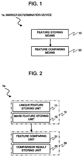
FIG. 1 is a block diagram illustrating a configuration of the marker generation device in a first exemplary embodiment of the present invention.
FIG. 2 is a block diagram illustrating a detailed configuration of the marker generation device in the first exemplary embodiment of the present invention.
FIG. 3 is a chart illustrating a configuration of a unique feature information table.
FIG. 4 is a chart illustrating a configuration of an identifier feature information table.
FIG. 5 is a view illustrating a feature space having the feature points of the identifier arranged therein.
FIG. 6 is a view illustrating a situation in which segment lines have been added to the feature space having the feature points of the identifier arranged therein.
FIG. 7 is a view illustrating the feature space having the unique features arranged therein.
FIG. 8 is a view illustrating the feature space having the feature points of the identifier and the unique features arranged therein.
FIG. 9 is a view illustrating a procedure of converting the data arrangement pattern of the identifier.
FIG. 10 is a view illustrating the feature points of the identifier.
FIG. 11 is a view illustrating the feature space having the feature points of the identifier arranged therein.
FIG. 12 is a view illustrating the feature space having the feature points of the identifier and the unique features arranged therein.
FIG. 13 is a view illustrating an example of a matrix pattern for conversion.
FIG. 14 is a view illustrating a configuration of the identifier converted by employed the matrix pattern for conversion shown in FIG. 13.
FIG. 15 is a view illustrating the feature points extracted from the identifier shown in FIG. 14.
FIG. 16 is a view illustrating the feature space having the feature points shown in FIG. 15 arranged therein.
FIG. 17 is a view illustrating the feature space having the feature points of the identifier shown in FIG. 16 and the unique features arranged therein.
FIG. 18 is a flowchart illustrating an operation of the marker generation device in the first exemplary embodiment of the present invention.
FIG. 19 is a block diagram illustrating a configuration of the marker generation device in a second exemplary embodiment of the present invention.
FIG. 20 is a block diagram illustrating a detailed configuration of the marker generation device in the second exemplary embodiment of the present invention.
FIG. 21 is a view illustrating an example of the background video image.
FIG. 22 is a view illustrating the feature space having the feature points arranged therein.
FIG. 23 is a view illustrating the feature space in which the feature points added with the numbers have been arranged.
FIG. 24 is a chart illustrating a configuration of the feature point information table.
FIG. 25 is a view illustrating the feature space in which the segment lines are drawn.
FIG. 26 is a view illustrating designations of the segments.
FIG. 27 is a view illustrating the coordinates of the segments.
FIG. 28 is a chart illustrating a configuration of a feature point number distribution diagram (frequency distribution).
FIG. 29 is s a view illustrating a situation in which the feature points are extracted from the identifier.
FIG. 30 is a view illustrating the feature space having the feature points arranged therein.
FIG. 31 is a flowchart illustrating an operation of the marker generation device in the second exemplary embodiment of the present invention.
FIG. 32 is a block diagram illustrating a configuration of the marker generation device in a third exemplary embodiment of the present invention.
FIG. 33 is a block diagram illustrating a detailed configuration of the marker generation device in the third exemplary embodiment of the present invention.
FIG. 34 is a view illustrating a situation in which respective feature points are mapped onto the invariant feature space with a feature point No. 5 defined as a basis.
FIG. 35 is a view illustrating a situation in which respective feature points are mapped onto the invariant feature space with a feature point No. 15 defined as a basis.
FIG. 36 is a view illustrating a situation in which respective feature points are mapped onto the invariant feature space with a feature point No. 89 defined as a basis.
FIG. 37 is a view illustrating a situation in which respective feature points are mapped onto the invariant feature space with a feature point No. 91 defined as a basis.
FIG. 38 is a view illustrating a situation in which all feature points shown in FIG. 22 are mapped onto the invariant feature space.
FIG. 39 is a view illustrating a situation in which segment lines are added to the invariant feature space.
FIG. 40 is a view illustrating the invariant feature space in which the segments having one feature point or more arranged therein are hatched in a gray color.
FIG. 41 is a view illustrating a situation in which the feature points of the identifier are mapped onto the invariant feature space.
FIG. 42 is a view illustrating a marker pattern generation scope in the invariant feature space.
FIG. 43 is a view illustrating the marker pattern generation scope in which the segments having one feature point or more arranged therein are hatched in a gray color.
FIG. 44 is a flowchart illustrating an operation of the marker generation device in the third exemplary embodiment of the present invention.
FIG. 45 is a block diagram illustrating a configuration of the marker detection device.
FIG. 46 is a block diagram illustrating a detailed configuration of the marker detection device.
FIG. 47 is a view illustrating an example of the detection-targeted video image.
FIG. 48 is a view illustrating an example of the feature points extracted from the detection-targeted video image.
FIG. 49 is a flowchart illustrating a procedure of the marker detection method.
FIG. 50 is a block diagram illustrating a configuration of the marker generation detection device.
FIG. 51 is a block diagram illustrating a detailed configuration of the marker generation detection device.
FIG. 52 is a block diagram illustrating a configuration of the marker generation detection system.
Description of embodiments
Hereinafter, the preferred exemplary embodiments of the marker generation device, the marker generation detection system, the marker generation detection device, the marker, the marker generation method, and the marker generation program relating to the present invention will be explained by making a reference to the accompanied drawings.
The First Exemplary Embodiment of the Marker Generation Device and the Marker Generation Method
At first, the first exemplary embodiment of the marker generation device and the marker generation method of the present invention will be explained by making a reference to FIG. 1. The same figure is a block diagram illustrating a configuration of the marker generation device of this exemplary embodiment.
(I) (Marker Generation Device)
As shown in FIG. 1, a marker generation device 1a is provided with a feature comparing means 10 and a marker pattern generating means 20.
The feature comparing means 10 includes a feature comparing unit 11 and a comparison information storing unit 12 as shown in FIG. 2.
The feature comparing unit 11 inputs "the unique feature information table" from the outside. And, the feature comparing unit 11 inputs "the identifier feature information table" from the outside or the marker pattern generating means 20. The comparison information storing unit 12 stores "the unique feature information table" and "the identifier feature information table"
"The unique feature information table" is a table in which data related to the unique features arranged in a predetermined space has been put together. This "unique feature information table", as shown in FIG. 3, may include "a serial number of the table" (A), "a serial number of the unique feature" (B), "an x coordinate of the unique feature" (C), and a y coordinate of the unique feature" (D) as an item, respectively.
When one unique feature information table, or two or more exists, "the serial number of the table" is indicative of the number (No.) added to each unique feature information table. When the video image to be inputted by a video image inputting means 30 (to be later described) is configured of a plurality of frame images, the above number is equivalent to a number added for each frame image.
"The serial number of the unique feature" is indicative of a number added to each of a plurality of the unique features.
"The x coordinate of the unique feature" is indicative of an x coordinate of the above unique feature in the predetermined space.
"The y coordinate of the unique feature" is indicative of a y coordinate of the above unique feature in the predetermined space.
Additionally, the predetermined space includes, for example, the feature space, the invariant feature space, the unique feature space and the like.
Further, the feature space, the invariant feature space, and the unique feature space will be explained in details in the second exemplary embodiment. In addition, the method of extracting the unique features or the like will be also explained in details in the second exemplary embodiment.
"The identifier feature information table", as shown in FIG. 4, may include "a serial number of the identifier" (A), "a serial number of the feature point" (B), "an x coordinate of the feature point" (C), and "a y coordinate of the feature point" (D) as an item, respectively.
"The serial number of the identifier" is indicative of a number added to one identifier, or each of two or more identifiers. Further, "the serial number of the identifier" may indicate a number added to the identifier not subjected to the conversion and a number added to the identifier subjected to the conversion in such a manner that they are distinguished from each other.
"The serial number of the feature point" is indicative of a number added to one feature point, or each of two or more feature points based upon the identifier.
"The x coordinate of the feature point" is indicative of an x coordinate of the above feature point in the predetermined space.
"The y coordinate of the feature point" is indicative a y coordinate of the above feature point in the predetermined space.
The feature comparing unit 11 may cause the comparison information storing unit 12 to store this "identifier feature information table" of which number is one, or two or more.
Additionally, "the predetermined space" includes, for example, the feature space, the invariant feature space and the like.
Further, "the feature point" includes the feature point extracted from the identifier, the feature point arranged in the feature space, invariant feature arranged in the invariant feature space, and the like.
These feature space and invariant feature space will be explained in details in the third exemplary embodiment. In addition, the method of extracting the invariant features, or the like will be also explained in details in the third exemplary embodiment.
Further, the feature comparing unit 11 takes out "the unique feature information table" and "the identifier feature information table" from the comparison information storing unit 12.
Next, the feature comparing unit 11 makes a reference to "the identifier feature information table" and arranges the feature points of the identifier in the predetermined space (for example, feature space). The predetermined space having these feature points arranged therein is shown in FIG. 5 and FIG. 6. FIG. 5 is a view illustrating a situation in which the feature points extracted from a QR code, being the identifier, are arranged in the feature space. FIG. 6 is a view illustrating a situation in which the segments having the feature points arranged therein are filled-in in a black color.
Continuously, the feature comparing unit 11 takes out the coordinates of the unique features from "the unique feature information table". And, the feature comparing unit 11 arranges the unique features in the predetermined space (for example, feature space) according to these coordinates. The predetermined space having these unique features arranged therein is shown in FIG. 7. In the same figure, the segments with a white color are the unique features.
And, the feature comparing unit 11 selects the feature points of the identifier matching with the unique features, and counts the number thereof.
This process may be performed by superposing an arrangement of the unique features shown in FIG. 7 and an arrangement of the feature points shown in FIG. 6 upon each other and determining whether or not the former matches with the latter. Further, a determination thereof may be made by comparing/collating the coordinate of the feature point of the identifier with the coordinate of the unique feature, and determining whether or not the former matches with the latter.
That is, the feature comparing unit 11 arranges the feature points of the identifier in the predetermined space having the unique features arranged therein, and counts the number of the feature points of the identifier arranged in a segment identical to that of the unique feature.
A result of this superposition is shown in FIG. 8. In FIG. 8, the segments indicated by double-square symbols are indicative of the segments having the feature points matching with the unique features arranged therein. With the case shown in the same figure, 26 feature points, out of 247 feature points of the identifier, match with the unique features. This count number (26 in FIG. 8) is stored in the comparison information storing unit 12.
Next, the feature comparing unit 11 determines whether or not "the identifier feature information table" not subjected yet to a process of matching with the unique features has been stored in the comparison information storing unit 12.
When the above "identifier feature information table" exists as a result of the determination, the feature comparing unit 11 takes out the above "identifier feature information table" from the comparison information storing unit 12.
And, the feature comparing unit 11 performs the matching process having the above-described content for the above "identifier feature information table". In addition, the feature comparing unit 11 counts the number of the segments having the feature points of the identifier matching with the unique features arranged therein, and causes the comparison information storing unit 12 to store this count value.
The comparison information storing unit 12 stores data and a program related to the matching process (process of counting the number of the feature points matching the unique features in the predetermined space) to be performed by the feature comparing unit 11.
Further, the comparison information storing unit 12 stores "the unique feature information table", "the identifier feature information table", the count value obtained by the matching process, and the like.
The count value is stored correspondingly to the number (No.) added to the identifier not subjected to the conversion or the identifier subjected to the conversion. This count value is also stored in a marker pattern storing unit 22.
The marker pattern generation means 20 includes a marker pattern generating unit 21 and the marker pattern storing unit 22 as shown in FIG. 2.
The marker pattern generating unit 21 inputs date related to the identifier from the outside. This data related to the identifier contains data displayed in a data region of the identifier. The date related to the identifier is stored in the marker pattern storing unit 22.
Further, the marker pattern generating unit 21 performs a process of converting the identifier according to a predetermined rule. The so-called process of converting the identifier points to a process of converting a sequence pattern of data displayed in the data region of the identifier while keeping the above data itself at an identical value.
Specifically, the conversion may be performed with the following method.
An example of the identifier is shown in FIG. 9(i). It is assumed that the QR code is employed as the identifier. However, the identifier is not limited to the QR code, and may contain various codes such as a barcode and a two-dimensional code.
Herein, the QR code, being the identifier, includes a positioning symbol and a data region.
The positioning symbol is a symbol arranged in a corner of the QR code in order to decide a loading-in direction of the data indicated in the data region. Detecting this positioning symbol enables the corner or the edge of the QR code to be specified, and the loading-in scope and the loading-in direction of the data region to be specified.
The data region is a region having the data displayed therein. In the QR code, the almost part other than the positioning symbol comes under the data region. In this data region, normally, the data is displayed in a binary value of the white cell or the black cell.
With the data related to the identifier inputted from the outside, the marker pattern generating unit 21 can recognize that the above identifier has, for example, the arrangement pattern of the data shown in FIG. 9(i).
Further, the marker pattern generating unit 21 takes out the matrix pattern for conversion from the marker pattern storing unit 22.
The matrix pattern for conversion, which is employed at the moment of converting the data arrangement pattern of the identifier, is a pattern as shown in the same figure (ii), for example.
The display pattern with the white cell or the black cell that this matrix pattern for conversion indicates may be decided arbitrarily, or it may be also decided according to a predetermined rule. As an example of the latter, for example, there is the case in which the cells are arranged repeatedly in an order of two white cells and one black cell (for example, see FIG. 13).
The marker pattern generating unit 21 converts the data for each cell of the data region of the identifier by employing the matrix pattern for conversion. That is, dependent upon which color (data) is used for a cell of the matrix pattern for conversion, the method of converting one cell of the data region of the identifier corresponding to the above cell is governed.
This data conversion is performed according to a predetermined rule. A logic equation such as Exclusive-OR may be employed for the predetermined rule (FIG. 9(iii)). Specifically, for example, when the color (data) of one cell of the matrix pattern for conversion is white, the data of the corresponding cell of the identifier is not converted, namely, as it stands. That is, the white cell remains the white cell, and the black cell remains the black cell.
On the other hand, when the color (data) of one cell of the matrix pattern for conversion is black, the data of the corresponding cell of the identifier is reversed. That is, the white cell is converted into the black cell, and the black cell is converted into the white cell.
A result of having converted the data of each cell of the identifier shown in FIG. 9(i) according to this rule is shown in FIG. 9(iv).
Next, the marker pattern generating unit 21 extracts the feature points from the identifier subjected to the conversion. These extracted feature points are shown in FIG. 10.
Continuously, the marker pattern generating unit 21, as shown in FIG. 11, arranges the extracted feature points in the feature space. Further, the marker pattern generating unit 21 partitions the above feature space into a plurality of the segments, and obtains the number of the arranged feature points for each segment. In addition, the marker pattern generating unit 21 selects the segments in which the number of the feature points is equal to more than a predetermined number. In FIG. 11, the segments in which the number of the feature points is "one (1)" or more are displayed in a black color.
And, the marker pattern generating unit 21 generates "the identifier feature information table" containing the coordinates of the segments in which these feature points have been arranged in a predetermined number. The marker pattern generating unit 21 causes the comparison information storing unit 12 and the marker pattern storing unit 22 to store the generated "identifier feature information table".
This "identifier feature information table" is stored in the comparison information storing unit 12, thereby allowing the feature comparing unit 11 to perform the matching process by making a reference to the above "identifier feature information table". That is, the feature comparing unit 11 arranges the segments containing the feature points extracted from the identifier subjected to the conversion in the feature space shown in FIG. 7. A situation of this arrangement is shown in FIG. 12. And, the feature comparing unit 11 counts the number of the feature points matching with the unique features, and causes the comparison information storing unit 12 to store this count value. Additionally, the count value is "20" in FIG. 12.
Likewise, when another matrix pattern for conversion (FIG. 13) is furthermore stored in the marker pattern storing unit 22, the marker pattern generating unit 21 takes out this, and converts the data of the identifier. This conversion result is shown in FIG. 14.
Next, the marker pattern generating unit 21 extracts the feature points of the identifier subjected to the conversion. These extracted feature points are shown in FIG. 15.
Continuously, the marker pattern generating unit 21 arranges the extracted feature points in the feature space, and partitions the above feature space into a plurality of the segments, and obtains the number of the arranged feature points for each segment. And, the marker pattern generating unit 21 selects the segments in which the number of the feature points is equal to more than a predetermined number. A situation of this selection is shown in FIG. 16. In the same figure, the segments in which the number of the feature points is "one (1)" or more are displayed in a black color.
And, the marker pattern generating unit 21 generates "the identifier feature information table" containing the coordinates of the segments in which these feature points have been arranged in a predetermined number. The marker pattern generating unit 21 causes the comparison information storing unit 12 and the marker pattern storing unit 22 to store the generated "identifier feature information table".
This "identifier feature information table" is stored in the comparison information storing unit 12, thereby allowing the feature comparing unit 11 to perform the matching process by making a reference to the above "identifier feature information table". That is, the comparison information storing unit 12 arranges the segments containing the feature points extracted from the identifier subjected to the conversion in the feature space shown in FIG. 7. A situation of this arrangement is shown in FIG. 17. And, the feature comparing unit 11 counts the number of the feature points matching with the unique features, and causes the comparison information storing unit 12 to store this count value. Additionally, the count value is "17" in FIG. 17.
In addition, the marker pattern generating unit 21 selects the identifier having a largest count value, out of the identifier not subjected to the conversion and one identifier subjected to the conversion, or two or more.
Herein, the count value of the identifier not subjected to the conversion is "26" (see FIG. 8). Further, the count value of the identifier converted with the matrix pattern for conversion of FIG. 9(ii) is "20" (see FIG. 12). And, the count value of the identifier converted with the matrix pattern for conversion of FIG. 13 is "17" (see FIG. 17). The identifier having a largest count value, out of them, is the identifier not subjected to the conversion. The marker pattern generating unit 21 selects this identifier not subjected to the conversion as the detection marker.
Additionally, when the QR code, being the identifier, is decoded, in a case in which the process is performed only with the single matrix pattern, the QR code may be decoded immediately; however, in a case in which the matrix pattern is selected from among a plurality of the matrix patterns, and the conversion process is performed by employing the selected matrix pattern, it is necessary to determine which matrix pattern for conversion of the cell feature has been used. Hence, classification information of the matrix pattern for conversion of the cell feature used for the process of converting the QR code is desirably incorporated within the QR code as data. With this, the decoding process is capable of simply performing the conversion into the original data cell only by loading in the matrix pattern information used for the conversion process from the QR code, and taking the matrix pattern for conversion of the cell feature corresponding hereto and Exclusive-OR.
(II) Marker Generation Method
Next, an operation of the marker generation device (marker generation method) of this exemplary embodiment will be explained by making a reference FIG. 18.
The same figure is a flowchart illustrating a predetermined procedure of the marker generation method of this exemplary embodiment.
The feature comparing unit 11 of the feature comparing means 10 inputs "the unique feature information table" from the outside. The comparison information storing unit 12 stores the above "unique feature information table" (Step 10).
Further, the feature comparing unit 11 inputs "the identifier feature information table" from the outside or the marker pattern generating means 20. The comparison information storing unit 12 stores the above "identifier feature information table" (Step 11).
The feature comparing unit 11 takes out "the unique feature information table" from the comparison information storing unit 12 (Step 12). Further, the feature comparing unit 11 takes out "the identifier feature information table" from the comparison information storing unit 12 (Step 13).
In addition, the feature comparing unit 11 takes out the coordinates of the unique features from "the unique feature information table". And, the feature comparing unit 11 arranges the unique features in the predetermined space according to the above coordinates.
Further, the feature comparing unit 11 arranges each of the feature points shown in "the serial number of the feature point" of "the identifier feature information table" in the predetermined space according to the x coordinate shown in "the x coordinate of the feature point" and the y coordinate shown in "the y coordinate of the feature point" (Step 14).
Next, the feature comparing unit 11 selects the segments containing the feature points of the identifier matching with the unique features (Step 15).
The description continues in the full USPTO document.
 Lapsed, fee not paid12 drawings