Lapsed, fee not paid9 drawings
Telecom & Networks · US 8,693,340 B2
Method and apparatus for least cost routing using multiple path accumulated constraints
A cost of a path may not be the only factor in searching for a path solution in a network.
US 8,693,345 B2 · Assignee: Mayflower Communications Company, Inc. · Inventors: Lee; Seoung Bum et al.
Sheet 1 of 19 from the published document. All sheets in the USPTO PDF
System and method for topology management of dynamic ad hoc wireless communication networks. The network nodes are organized in a multi-level hierarchical architecture whereby the nodes at each level are managed by nodes at the next higher level. In a three-layer network, leaf nodes populate the lowest level, cluster head nodes the intermediate level, and regional head nodes the highest level. Priority-based backbone tree paths are constructed by selecting and connecting high capability nodes, such that the unselected nodes are one-hop away from a connected node. In a two backbone tree path construction, a primary backbone tree path carries the high priority traffic and a secondary backbone tree path carries the lower priority traffic. The connectivities of the backbone tree paths are maintained dynamically. So also are high priority traffic flows using the Dynamic Priority Threshold mechanism with High Fidelity Monitoring and traffic siphoning via unutilized network resources.
Network topology determines the availability and characteristics of the "connection" between any two nodes of the network. A "connection" is defined by the number of consecutive links forming the connection and the available transmission capacities of those links. These characteristics determine the data transmission reliability and delay between the "connected" network nodes. For a network of fixed nodes, the topology is essentially static, being determined by the physical connections between the nodes. For a network with wireless mobile nodes, however, the topology is dynamic. In such ad hoc mobile networks, the topologies must be continuously managed in a self-forming manner by dynamically selecting from among multiple possible topology choices. Current wireless network topology management technology employs network planning tools of the kind used with cellular communications networks
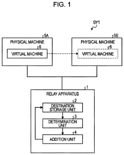
1 of 19 drawing sheets so far from the published document, cropped to the drawing. Every sheet is in the USPTO PDF.
What the patent claimed, word for word. All of it is now free to use.
Independent claims stand on their own. The others add detail to the claim they name.
The present invention generally relates to topology management in wireless communications networks. More particularly, the invention relates to topology management in ad hoc dynamic environments comprising highly mobile nodes employing different types of radios and unbalanced dynamic data traffic distribution among different traffic types and priorities.
Network topology determines the availability and characteristics of the "connection" between any two nodes of the network. A "connection" is defined by the number of consecutive links forming the connection and the available transmission capacities of those links. These characteristics determine the data transmission reliability and delay between the "connected" network nodes.
For a network of fixed nodes, the topology is essentially static, being determined by the physical connections between the nodes. For a network with wireless mobile nodes, however, the topology is dynamic. In such ad hoc mobile networks, the topologies must be continuously managed in a self-forming manner by dynamically selecting from among multiple possible topology choices.
Current wireless network topology management technology employs network planning tools of the kind used with cellular communications networks. The utility of such planning tools, however, is limited to infrastructure networks, i.e. networks that include base stations operating with a single (generally omni-directional) type of radio. The ad hoc network, in contrast, is an infrastructure-less network in which the network elements (nodes) move around freely and the topology and networking conditions change continuously. Consequently, the network management tools designed for the reasonably static topologies and network conditions of the infrastructure networks are unsuited for application to the ad hoc mobile network dynamic environments.
Topology management in ad hoc dynamic environments is challenging for the following reasons:
the topology is highly dynamic and continuously changing due to the high mobility of the nodes;
the mobile nodes (platforms) are greatly varied, i.e. heterogeneous in nature, employing different types of radios with differing capabilities; and
the traffic is unbalanced with dynamically varying traffic distributed among different traffic types and priorities.
Disaster response to large-scale catastrophes, requiring the implementation of an information network to support the delivery of effective rescue services over a large area, presents a good example of an ad hoc dynamic environment that could benefit from the present invention. Such a network could include different types of land, sea, and/or air vehicles employing a random mix of commercially available wireless technologies, including such varied ones as Wi-Fi, Bluetooth, and UMTS-TDD Ad Hoc, among others. As such ad hoc communication devices abound, they come together in unplanned topologies, and when the networks become dense, as, for example, in an urban downtown, congestion and latency grow rapidly. A topology management system is required to dynamically set-up and manage such networks.
Another area that could benefit from the present invention is the US Department of Defense's (DoD's) pursuit of a comprehensive network-centric transformation of its forces. Initiatives such as the Navy FORCEnet and programs such as the Army Warfighter Information Network--Tactical (WIN-T) are central to this transformation. Such DoD efforts are predicated on the dynamic networking of radios with directional or omnidirectional antennas on a variety of platforms operating in a dynamic and ad hoc manner, and delivering over this network a variety of services with varying Qualities of Service (QoS) and multiple levels of security.
A method for managing ad hoc networks with directional antennas was disclosed in U.S. Pat. No. 7,830,820 B2, "Method and Apparatus for Directional Networking Topology Management," issued to Duke et al. A number of systems for managing antenna connection parameters in order to control the topology have also been disclosed (See, e.g. U.S. Pat. No. 6,990,080 B2, "Distributed Topology Control for Wireless Multi-hot Sensor Networks," Bahl et al.; US Patent Application No. US 2007/0081556 A1, "Antenna Management System," Evans et al.; and US Patent Application No. US 2007/0195746 A1, "Topology Management, Power Control and Cross-layer Design for Wireless Mobile Ad Hoc Networks with Directional Antennas," Ryu et al.) All these inventions, however, have focused on forming and managing antenna connectivity in the neighborhood of a node, and the topologies they form have been based on neighborhood connection considerations that fail to take into account the network-wide traffic loads and patterns. These are serious limitations, since such topology formations are ill-suited to supporting ad hoc networks with dynamically changing network traffic loads and patterns.
Topology management for establishing connectivity on the basis of the local traffic load has been disclosed in U.S. Pat. No. 7,855,997 B2, "Long Range Scheduling for Directional Antenna MANET Networks," issued to Adams et al. These traffic scheduling and connectivity considerations, however, are also, as above, limited to the immediate neighborhood of the node, failing to take into account the network-wide traffic loads and patterns. Furthermore, packet priorities are not factored into scheduling the forwarding of the data packets. These constitute serious limitations since traffic load increases elsewhere in the network can potentially impact the delivery of the local packet, for example, where a congested area is en-route the packet's transit path. Also, where the topology management fails to treat high priority packets preferentially, their delivery reliability and latency performance suffer.
Methods that implement topological connectivity over the entire network have also been disclosed. (See, e.g., U.S. Pat. No. 6,791,949 B1, "Network Protocol for Wireless Ad Hoc Networks," Ryu et al.; U.S. Pat. No. 7,606,171 B1, "Skeletal Node Rules for Connected Dominating Set in Ad-Hoc Networks," Young et al.; US Patent Application No. 2011/0090787 A1, "Spanning Tree Flooding Backbone Systems and Methods for Link State Routed Networks," Smith et al.) As above, however, these methods too do not take into account the network-wide traffic loads and patterns and data packet priorities.
Preferential scheduling of higher priority packets at a network node has been disclosed in U.S. Pat. No. 7,417,999 B1, "Priority Propagation in a Multi-level Scheduling Hierarchy," issued to Charny et al. But this patent only addresses priority-based transmission of data packets at a single node, and not across the network. This approach too, as above, fails to take into account the specifics of the network topology in formulating the forwarding strategy, and the packet forwarding strategy implemented may not be supportable by the prevailing topology.
There exists a need for a topology management system and method that manages network-wide topology and influences data packet forwarding based on the traffic loads, patterns, and priorities across the network. This requires a topology management system that dynamically tracks the network traffic characteristics and forms and manages the topologies accordingly. The system and method disclosed and claimed herein provide an effective means to dynamically manage topology and network performance in such scenarios.
A topology management system and method for optimizing the performance of ad hoc dynamic wireless communication networks carrying diverse traffic flows with different quality of service requirements and priorities is disclosed. The topology management invention herein utilizes antenna directionality, priority-aware load balancing, and traffic siphoning to optimize the overall network performance.
The instant topology management invention uses a hierarchical approach for managing the network topology. This multi-level approach to topology management allows increased scalability and greater distribution. Scalability and distributed management features are essential for highly dynamic networking environments since topology adjustments and optimizations must be executed rapidly. The three levels are designated as leaf nodes (bottom level, 1), cluster head nodes (middle level, 2), and regional head nodes (top level, 3). Each level is managed via its individual database, namely, Neighborhood Status Table (NST) for level 1, Cluster Status Table (CST) for level 2, and Global Status Table (GST) for level 3.
The leaf nodes generate periodic beacon messages, which provide detailed information about their communication link quality. The beacon messages from the leaf nodes are gathered by the cluster head node to create a Neighborhood Status Table (NST), which identifies the members of a given group, for example, an air or land ambulatory rescue group, forming a cluster. The NSTs from different clusters are collected by the regional head node to create a Cluster Status Table (CST) that describes the regional topology (identifying, for example, the clusters involved in the rescue operation, e.g., air and/or land ambulatory rescue cluster, field surgical cluster, first aid EMT cluster, firefighting and hazardous waste disposal cluster, etc.). A number of such CSTs are grouped by a central command authority into a Global Status Table (GST), which provides a broad view of the network topology.
The present invention monitors the performance of such distributed networks by making edge-to-edge probe based measurements of low complexity executed at the edge nodes, i.e., at the regional heads and cluster-heads. Edge nodes are typically high capability nodes, such as those having internet-working capabilities and high capacity communication links. The edge-to-edge probe based measurements involve transmission of time-stamped probe packet trains over the target paths. A probe packet train is composed of scores of fixed size user datagram packets transported at a constant bit rate (UDP/CBR). Arrivals of the time-stamped probe packets are monitored at the ingress edge nodes, and network performance metrics, such as end-to-end delay, jitter, packet loss rate, and throughput etc., determined. These measurements are used to select the best topology optimization algorithm for optimal network performance.
Priority-aware load balancing is at the core of achieving performance optimization in the instant topology management invention. In one embodiment, it implements two backbone tree traffic transportation pathways, a primary backbone tree and a secondary backbone tree. The primary backbone tree is used for high priority traffic, and the secondary backbone tree is used for lower priority traffic. Although two backbone trees are discussed in detail herein, a greater number of backbone trees can be similarly used for even more discriminatory priority load balancing, however, at the cost of increased complexity. Such multiple-tree implementations are within the scope of the present invention. The multiple-tree architecture enables the topology management invention to protect the integrity of high priority flows, and meeting their service guarantees even under extremely congested network traffic conditions.
The backbone tree function is enabled via the following steps:
Backbone Selection, for selecting the backbone tree nodes,
Backbone Connection, for completing the backbone tree connections so that all nodes have access to the backbone tree, and
Backbone Maintenance, for maintaining backbone tree optimality and connectivity in the presence of node mobility. These steps are used for constructing and maintaining both the primary backbone tree and the secondary backbone tree. Once constructed, the primary and secondary backbone trees are dynamically maintained and their performances assured despite any disruptions caused by effects such as node mobility, network failure, or insertion of new network nodes.
The topology management invention herein uses traffic siphoning to further protect the high-priority flows, when needed, such as when part of the network is overloaded from excessive traffic congestion or becomes temporarily unavailable due to network failure. In such cases, traffic siphoning redirects traffic away from the excessively congested or problematic area(s) and delivers the information to its intended destination via indirect paths. For data transport, these indirect siphoning paths exploit the unutilized part of the network, away from the excessively congested or temporarily unavailable backbone tree paths.
Briefly, the present invention comprises a flexible high-performance layered management split data architecture that sustains multiple simultaneous directional antenna links and supports traffic with different priorities and characteristics. The invention has the following characteristics:
Management and Routing Independence: The network management infrastructure is independent of the data routing infrastructure, thus enabling utilization of multiple simultaneous directional link capabilities and mitigating single points of failure. For instance, the cluster head node with which a leaf node associates for management purposes may be different from the node with which it associates for forwarding high priority data, which in turn may be different from the node with which it associates for forwarding low priority data.
Layered Management: Network management occurs through a hierarchical approach in which the nodes are organized into multiple layers of hierarchy. A three-layered hierarchical management structure is disclosed herein; however, additional management layers may be added if desired and are within the scope of the instant invention. The signaling messages for network management traverse across this hierarchical structure.
Split Data: The traffic is split onto different logical backbone tree paths according to the traffic flow priorities. Higher priority traffic flows are forwarded along one logical backbone tree path whereas lower priority traffic flows are forwarded along a different independent logical backbone tree path.
Other embodiments apparent to one of ordinary skill in the art are within the scope of the present invention. The drawings, however, are primarily for illustration and must not be construed as limiting. The scope of the invention is to be limited only by the claims, and not by the drawings or description herein.
The objects, features, and advantages of the present invention are more fully understood when considered in conjunction with the following accompanying drawings:
FIG. 1 presents an overview of the instant invention's topology management methodology;
FIG. 2 depicts an exemplary three-tier hierarchical approach for topology management;
FIG. 3 shows an example Neighborhood Status Table;
FIG. 4 shows an example Cluster Status Table;
FIG. 5 shows an example Global Status Table;
FIG. 6 shows use of antenna directionality in topology optimization;
FIG. 7 illustrates an example of a priority-aware two backbone tree network;
FIG. 8 shows the use of traffic siphoning for bypassing a congested portion of the network;
FIG. 9 illustrates the process for selecting the primary backbone tree nodes;
FIG. 10 represents completion of the primary backbone tree node selection process;
FIG. 11 presents an example node selection flowchart for a White node.
FIG. 12 presents an example node selection flowchart for a Green node.
FIG. 13 presents an example node selection flowchart for a Black node.
FIG. 14 presents an example of a primary backbone tree B-G-G-B connection;
FIG. 15 shows resolution of the primary backbone tree B-G-G-B connection issue;
FIG. 16 presents primary backbone tree maintenance issues associated with new nodes joining the network;
FIG. 17 shows integration of the new nodes into the network and continued maintenance of the primary backbone tree;
FIG. 18 shows secondary backbone tree construction;
FIG. 19 presents a schematic sketch showing High Fidelity Monitoring and Dynamic Priority Threshold mechanism.
Topology management starts from topology discovery. Although it is possible that the initial network topology information may be available a priori, such as from initial planning, the instant topology management tool is nevertheless able to quickly discover an accurate network topology through network monitoring and analysis. This ability to rapidly discover the network topology is particularly important where, as here, the wireless communication network topologies change dynamically and constantly due to node mobility.
FIG. 1 illustrates the instant invention's topology management methodology. Based on the topology information, the system herein continuously monitors and analyzes the network performance. The monitored characteristics and measured performance are analyzed to select and execute the most appropriate topology optimization. Since the envisioned ad hoc communication network is highly dynamic, the network topology is continuously monitored, analyzed, and optimized to maintain optimal performance. These processes iterate through the lifetime of the ad hoc dynamic wireless network.
A hierarchical approach that distributes and manages the network at three logical management levels is used (FIG. 2). This multi-level approach makes topology management scalable and better distributed. Scalability and distributed management are essential for highly dynamic networking environments because topology adjustments and optimizations have to be executed rapidly. The three management levels employed herein are designated respectively as leaf nodes (bottom level 1) 210, cluster head nodes (middle level 2) 220, and regional head nodes (top level 3) 230. Each level is managed via its characteristic database, namely, Neighborhood Status Table (NST) at level 1 (See, e.g., FIGS. 2 and 3), Cluster Status Table (CST) at level 2 (See, e.g., FIGS. 2 and 4), and Global Status Table (GST) at level 3 (See, e.g., FIGS. 2 and 5).
A leaf node 210 is typically a member of a cluster. A cluster-head node manages a group of leaf nodes, e.g. 210, for topology and link quality management. The cluster head node, e.g. 220, is generally a high capability mobile node, such as one equipped with greater computational power, more networking functionalities, and larger bandwidth than the leaf nodes. All traffic (e.g., data, signaling, etc.), e.g. 215, flows to and from a leaf node through a cluster head node. Thus, the cluster head node is typically involved in performing higher level functions, such as packet forwarding, signaling, topology control, and link quality monitoring.
In general, a leaf node, e.g. 210 may have multiple cluster head nodes in its radio range. A leaf node always binds itself to a nearby primary cluster head node (i.e., current binding cluster head node), with secondary cluster head node, tertiary cluster head node, and so forth, available as back-ups. The preferred cluster head node binding is generally mandated by the mission plan but a leaf node always endeavors to bind itself to a best conditioned cluster head node where the term `best condition` always implies bidirectional communication between the leaf node and the cluster head node.
Cluster head nodes, e.g. 220, are either connected to regional head nodes, e.g. 230, or other (peer) cluster head nodes, e.g. 225, through high capacity directional antenna links. As mentioned above, cluster head nodes are higher capability nodes generally equipped with multiple communication technologies. Depending on the type and functional capabilities of a cluster head node, it may need to always communicate via a regional head node that typically will have even greater networking capability or a sufficiently or fully integrated networking capability. The cluster head node, e.g. 220, is intimately involved in topology management, topology optimization, and network performance monitoring.
A regional head node, e.g. 230, is typically connected to other (peer) regional head nodes, e.g. 235, thus providing extensive traffic forwarding capability through high bandwidth communication links. A regional head node could, therefore, either be linked to multiple cluster head nodes, e.g. 220, 225, and 228, or act purely as a relay, i.e. a forwarding or routing unit. An example of a regional head node is a wide body airplane that provides highly advanced functionalities such as waveform translations for multiple waveform types.
The leaf nodes, e.g. 210, within the cluster generate periodic beacon messages, e.g. 215, in which are embedded details about the beacon transmitter and its communication links. These beacon messages are collected in a Neighborhood Status Table (NST) 300 created by the cluster head node, e.g. 220, that organizes and manages the leaf nodes. The NST allows the cluster head node 220 to accurately maintain and manage the leaf nodes in its neighborhood.
FIG. 3 presents an example snapshot of a NST 300 residing at a cluster head node. The example NST lists node Identifiers (node IDs in the IPv6 format), node type, Signal-to-Noise (SNR) readings, Bidirectional Link Quality Indication (BLQI), GPS coordinates of leaf nodes, Affinity (a measure of the duration of the connectivity, i.e. the stability of the communication link), associated cluster head nodes, last timestamp, beacon message periodicity, number of missed beacon messages, and so forth. The SNR readings include downlink SNR and uplink SNR values. The SNR values represent weighted moving average values. The term "downlink" refers to the communication link from the cluster head node 220 (in FIG. 2) to the leaf node, e.g. 210, whereas the uplink indicates the communication link from the leaf node, e.g. 210, to the cluster head node, e.g. 220. BLQI describes the bidirectional link quality.
If both downlink SNR and uplink SNR readings are above their predefined threshold values, the BLQI will indicate a "good" reading. Otherwise, BLQI will indicate "poor," as illustrated in FIG. 3. The NSTs from different clusters are merged by a regional head node, e.g. 230, to create a Cluster Status Table (CST) that describes the regional topology. Typically, the CST resides at a regional head node, e.g. 230, and provides comprehensive detail about its regional network. FIG. 4 illustrates an example of a CST 400 that lists cluster-head node IDs; GPS coordinates, connection quality of the cluster head node (BLQI); associated regional head nodes and the qualities of their connections to the cluster head node (BLQI); neighboring cluster head nodes and the qualities of their connections to the cluster head node (BLQI); associated leaf node IDs and the qualities of their connections to the cluster head node (BLQI); primary and back-up cluster-head nodes for each leaf node; last update timestamps, and so forth.
The CST of FIG. 4 shows a leaf node with an IPv6 address 1001:1:0:345:80:17B:200C:F, which has CH1 as its primary cluster head node and CH3 as its secondary cluster head node. The CST reveals that the connection quality between the leaf node and CH1 has deteriorated to `poor.` In addition, it also shows that the connection quality between the leaf node and its backup cluster head node CH3 is in good condition. This condition results in CH1 delegating the ongoing communications with the leaf node to CH3. The cluster head node change is reflected in the subsequent beacon messages, and the associated NST 300, CST 400, and GST 500 are updated accordingly. This example also shows that associating a leaf node with multiple cluster head nodes substantially enhances network performance, network reliability, and network survivability.
The CSTs from regional head nodes are, in turn, combined by the command center to create a Global Status Table (GST) 500, providing a comprehensive view of the network topology (See, e.g., FIG. 5). The example GST 500 lists regional head node (RH) IDs, regional head node GPS coordinates and timestamps, regional head node networking status, neighboring regional head node status, associated cluster head nodes (CHs) and their status, and neighboring CHs that are not associated with RHs (but within the radio range) including the qualities of the CH connections. Once the network topology is identified, the network performance is monitored and assessed using local link quality monitoring and edge-to-edge probe based measurements.
The network's communication links are monitored continuously to verify link quality and link connectivity of the leaf nodes within the clusters. The link quality monitoring is performed by the exchange of beacon messages, e.g. 215 (FIG. 2), between each leaf node, e.g. 210, and its primary cluster head node, e.g. 220. The beacon messages, e.g. 215, are encoded with detailed information on the transmitting leaf node and it includes (but is not limited to) GPS coordinate, node type, beacon periodicity, associated CHs and their SNR measurements, and Link Quality Indicator. The cluster-wide link quality information is maintained in the Neighborhood Status Table (NST). e.g. 300, which serves as a current resource for cluster link quality and topology information.
The edge-to-edge probe based measurement is a low complexity distributed network performance measurement procedure that is executed at the edge nodes (certain regional head nodes and cluster head nodes). The more capable nodes within the respective management levels serve as edge nodes. The edge nodes typically have internet working capability and high capacity communication links. The edge-to-edge probe based measurement procedure involves the transmission of time-stamped probe packet trains over the target data path. A probe packet train is composed of scores of fixed size user datagram packets transported at a constant bit rate (CBR/UDP). At the ingress edge nodes, the arrivals of the time-stamped probe packets are monitored and network performance metrics, such as end-to-end delay, jitter, packet loss rate, throughput, etc., determined. These measurements are analyzed to select the best optimization algorithm for optimal network performance. For example, if "delay" is detected, the network is optimized to improve delay. Or, if frequent "packet loss" is detected, the network is optimized to improve reliability, and so forth.
To enhance the overall network performance, the instant invention exploits antenna directionality, priority-aware load balancing, and traffic siphoning. For example, in FIG. 6, the instant invention identifies through network monitoring that N3 670 is no longer the optimal relay node for the N0-N4 (610-690) node pair. It then determines based on the network status information (e.g. at NST 300, CST 400, and GST 500) that N1 630 is the new optimal backbone node (e.g., regional head node or cluster head node) for carrying the traffic, and changes the N0 610 antenna directivity from N3 675 to N1 635.
Priority-aware traffic load balancing is central to achieving performance optimization in the instant invention. As shown in FIG. 7, the preferred scheme implements two backbone trees, a primary backbone tree 710 and a secondary backbone tree 750. The primary backbone tree 710 is used for the higher priority traffic, and the secondary backbone tree 750 is used for lower priority traffic. As an example, node A, with a high priority Intelligence, Surveillance, Reconnaissance (ISR) video feed that has to be delivered to the command center 790, would use the primary backbone tree 710 for transporting the traffic. In contrast, node B, with low priority sensor data, would utilize the secondary backbone tree 750. Where the two backbone trees intersect, such as at node C, a strict priority-based preemption is used to maintain the integrity of the traffic flows along the primary backbone tree. This two-tree architecture protects the integrity of high priority flows and meets their service guarantees even under extremely congested conditions. Although a two-tree architecture is discussed herein, it will be apparent to one of ordinary skill in the art that tree architectures of greater plurality are possible with some additional complexity; such architectures based on more than two backbone trees are within the spirit and scope of the present invention.
In the dynamic ad hoc network scenario, the topology of the primary backbone tree, e.g. 710, is expected to vary constantly throughout the lifetime of the network. Consequently, in order to maintain sustained optimal networking performance, the optimal topology of the primary backbone tree 710 is continuously reevaluated and reconfigured as needed. Also, the primary backbone tree 710 is preferably provisioned to keep its asset utilization under a certain level to accommodate any sudden influx of high priority flows. This helps to maintain the integrity of the traffic flows along the primary backbone tree, e.g. 710, without experiencing unacceptable congestion. The utilization level of the primary backbone tree, e.g. 710, is a system parameter that can be established by the mission planners or the command center.
The secondary backbone tree 750 is used to transport low priority and delay tolerant traffic. A main purpose of the secondary backbone tree 750 is to protect the integrity of the high priority flows along the primary backbone tree 710. The secondary backbone tree 750 keeps the low priority traffic away from the primary backbone tree 710, thereby preventing the low priority traffic from competing with high priority flows for network resources. To the extent possible, the secondary backbone tree 750 is constructed to avoid any overlap of its nodes with the primary backbone tree 710 nodes and help disperse the low priority network loads away from the primary backbone tree 710.
The threshold for establishing a high priority level is a system parameter that determines the right of the traffic to utilize the primary backbone tree, e.g. 710, for transport. Traffic flows with priority levels equal to or higher than the priority threshold are transported over the primary backbone tree. Those with priority levels lower than the priority threshold are transported over the secondary backbone tree, e.g. 750. The priority threshold is a variable value that, if desired, can be changed dynamically depending on the primary backbone tree's current utilization level.
When the primary backbone tree, e.g. 710, becomes crowded with high priority traffic flows, the priority threshold is raised to protect the higher priority traffic flows from being impacted. For example, while traffic flows with priority levels 3 and 4 (priority level 1 being the highest) may earlier have been transported over the primary backbone tree, after the priority threshold increase, only the higher priority flow (i.e., priority 3) may be allowed in the primary backbone tree, e.g. 710, forcing the priority 4 flow to be transported over the secondary backbone tree, e.g. 750.
To further protect the high-priority flows, the instant topology management invention uses traffic siphoning (FIG. 8), when needed. Traffic siphoning 850 is employed when part of the network 825 is overloaded from excessive traffic or becomes temporarily unavailable due to reasons such as network failure. In such cases, traffic siphoning 850 directs traffic away from the excessively congested or problematic areas and delivers the information to its intended destination, e.g. the Command Center, via indirect paths. These indirect siphoning paths exploit the unutilized parts of the network for transport, away from the excessively congested or temporarily unavailable backbone tree paths. For instance, the traffic siphoning path shown in FIG. 8 is created at the outer edges of the network in order to circumvent the overloaded conditions at the backbone tree nodes C, D, E, and F. Traffic siphoning 850 results in creating redundant or extended backbone tree paths but, once they are no longer needed, subsequent topology optimization removes the unutilized redundancy.
Optimal dynamic network performance is achieved by employing the two backbone tree architecture, e.g. 710 and 750, which is dynamically configured and maintained to best suit the changing physical topology and traffic patterns. The primary backbone tree, e.g. 710, transports high priority traffic requiring highly assured networking performance, while the secondary backbone tree, e.g. 750, carries the low priority and delay tolerant flows, away from the primary backbone tree, e.g. 710. The tree construction is an approximation of the Minimum Connected Dominating Set (MCDS) in graph theory, where a subset of the connected graph forming the tree (i.e., MCDS nodes) can reach all non-MCDS nodes with a single hop. See, e.g., "Distributed Construction of Connected Dominating Set in Wireless Ad Hoc Networks", by P. J. Wan et al, Proceedings of IEEE Infocom, pp 1597-1604, volume 3, June 2002, New York, New York.
The ongoing construction and maintenance of the primary backbone tree and the secondary backbone tree entail the following steps:
Backbone Selection, which selects the backbone tree nodes;
Backbone Connection, which completes the backbone tree connections so that all the network nodes have one-hop access to the backbone tree nodes; and
Backbone Maintenance, which maintains backbone tree optimality and connectivity in the presence of node mobility. The primary backbone tree construction precedes the secondary backbone construction, which starts only after the primary backbone tree has been constructed. Where needed due to node mobility, the topologies of the two backbone trees are changed dynamically; however, although their shapes may change to accommodate the changing topologies, the trees remain connected and functional throughout the lifetime of the network. Once efficient primary and secondary backbone trees are constructed, they are effectively utilized to dynamically optimize network performance.
Primary Backbone Tree Construction:
A. Backbone Selection (FIGS. 9 and 10): In order to construct the primary backbone tree, the system must first select the backbone tree nodes from among the many candidates. High profile nodes (e.g. cluster head nodes and regional head nodes) are obvious candidates to serve as primary backbone tree nodes. In selecting the nodes for primary backbone tree construction, the node degree (i.e., number of 1-hop neighbors) for each node is used as a selection metric. Any node that lacks a backbone tree node as a 1-hop neighbor requests its "best neighbor" to become a backbone tree node (for it to have an access point for transporting its traffic via the backbone trees). The term "best neighbor" means the highest ranked node, and/or node with the best SNR, and/or node with the best data rate, and/or node with the highest degree of connectivity to adjacent neighbors, as required. At the completion of this backbone tree node selection process, each node in the network has either been selected as part of the backbone tree or has a 1-hop neighbor node that has been selected as one.
To further clarify the primary backbone tree construction process, an example is presented in FIG. 7, where the nodes are color labeled as either White, Green, or Black. A node is Black when it is part of the primary backbone tree, e.g. 710, Green when it is a 1-hop neighbor of a Black node, and White when it has no 1-hop Black node neighbor. (As shown in FIG. 7, the White nodes in the figures of this disclosure appear as small open circles, Black nodes as small dark circles, and Green nodes as black donuts consisting of a large black ring enclosing an open center.) In addition, a node is Black when it is providing access to the primary tree for at least one other 1-hop neighbor node. In other words, a Black node is an access point to the primary tree (i.e., Primary Access Point (PAP)) for other network nodes. The objective in the primary backbone tree construction is to designate all the nodes in the backbone tree network as either Black or Green. Based on this goal, the network selects the initial primary backbone tree nodes from the high capability cluster head and regional head nodes available.
FIG. 9 illustrates, by way of example, the initial stages of the primary backbone tree node selection process. The Command Center is inherently part of the primary backbone tree and is labeled as Black, causing its 1-hop neighbor nodes (connected to it by dashed lines), J and K, to be Green. If node E is a high profile unit (i.e., an important unit), it too becomes part of the primary backbone tree and turns Black. Then, by definition, E's 1-hop neighbors (connected to E with dashed lines), B, C, D, F, G, and H, become Green. This leaves A and I as White. In order to accommodate these two remaining White nodes, nodes B and H turn Black, becoming a part of the primary backbone tree. This changes nodes A and I (which are 1-hop away respectively from B and H) into Green.
FIG. 10 illustrates the outcome of the example backbone selection process.
The algorithms that facilitate the node selection process in one embodiment of the invention are schematically presented in FIGS. 11 through 13. While FIG. 11 presents a flowchart of the decision-making process by which a white node changes its color or otherwise secures its place in the network, FIGS. 12 and 13 show similar flowcharts for the Green and Black nodes respectively.
These processes are conducted through the transmission and reception of "Hello" messages that each network node broadcasts periodically for two-way communication with its neighbors. For leaf nodes, the beacon messages serve as the Hello messages. Likewise, cluster head nodes and regional head nodes also communicate with their Hello messages for updating and maintaining the CST and GST respectively.
In FIG. 11, upon receiving a Hello message, a White node W first determines whether the message is from a non-White node W10. If the answer is Yes, W then determines whether the transmitting node is a Black node W12. Where the message is received from a Black node, the white node W selects the most preferred Black node (from those in its vicinity) as its Primary Access Point and in the process turns itself Green W22. However, if the message from the non-white node is not from a Black node, it must be from a Green node, and then W selects the most preferred Green node from its neighborhood as its Primary Access Point (PAP) for accessing the network W14, whereby the selected Green node turns itself into a Black node and updates the neighbors of its change in color W15.
Where, on the other hand, the message received by W is from another White node W20 and W has Black neighbors, then W, as before, selects the most preferred Black node (from those in its vicinity) as its Primary Access Point, in the process turning itself Green W22. If, however, W does not have any Black neighbors but has Green neighbors W30, W again selects from among them W32 the most preferred Green neighbor as its PAP which turns Black, while W turns Green W14. Where W has only one Green neighbor, it selects that Green node as its PAP W33 turning it Black, even as W itself turns Green, and updating the neighbors accordingly W35. Furthermore, where W finds it has only White node neighbors, it either asks its most preferred local White node neighbor W42 to turn Black W44 if the Backbone Section Timer (BS Timer) W40 has expired or, if it has not, W waits for additional Hello messages W50. (When a node powers on for the first time, it starts a Backbone Selection Timer, and the Primary Backbone Selection ends when the BS Timer expires.)
The description continues in the full USPTO document.
About 6,114 words. The USPTO PDF has it with every drawing.
Fees are due 3.5, 7.5 and 11.5 years after grant. This patent expired on April 8, 2026, so the fee marked "not paid" was the one that went unpaid.
Dynamic management of wireless network topology with diverse traffic flows
Filed Oct 2011 · published Apr 2013Dynamic management of wireless network topology with diverse traffic flows
Filed Oct 2011 · granted Apr 2014Earlier publications, parents and continuations. None of them can still be enforced, or this patent would not be listed.
Prior art cited by the examiner or applicant. Useful when you check your own idea for novelty.
Everything on this page comes from the documents linked above.